EP4144951B1 - Support for drilling and bolting tool - Google Patents
Support for drilling and bolting tool Download PDFInfo
- Publication number
- EP4144951B1 EP4144951B1 EP22194281.6A EP22194281A EP4144951B1 EP 4144951 B1 EP4144951 B1 EP 4144951B1 EP 22194281 A EP22194281 A EP 22194281A EP 4144951 B1 EP4144951 B1 EP 4144951B1
- Authority
- EP
- European Patent Office
- Prior art keywords
- boom
- guide member
- shaft support
- shaft
- guide
- Prior art date
- Legal status (The legal status is an assumption and is not a legal conclusion. Google has not performed a legal analysis and makes no representation as to the accuracy of the status listed.)
- Active
Links
Images







Classifications
-
- E—FIXED CONSTRUCTIONS
- E21—EARTH OR ROCK DRILLING; MINING
- E21B—EARTH OR ROCK DRILLING; OBTAINING OIL, GAS, WATER, SOLUBLE OR MELTABLE MATERIALS OR A SLURRY OF MINERALS FROM WELLS
- E21B7/00—Special methods or apparatus for drilling
- E21B7/02—Drilling rigs characterised by means for land transport with their own drive, e.g. skid mounting or wheel mounting
-
- E—FIXED CONSTRUCTIONS
- E21—EARTH OR ROCK DRILLING; MINING
- E21B—EARTH OR ROCK DRILLING; OBTAINING OIL, GAS, WATER, SOLUBLE OR MELTABLE MATERIALS OR A SLURRY OF MINERALS FROM WELLS
- E21B7/00—Special methods or apparatus for drilling
- E21B7/02—Drilling rigs characterised by means for land transport with their own drive, e.g. skid mounting or wheel mounting
- E21B7/025—Rock drills, i.e. jumbo drills
-
- E—FIXED CONSTRUCTIONS
- E21—EARTH OR ROCK DRILLING; MINING
- E21B—EARTH OR ROCK DRILLING; OBTAINING OIL, GAS, WATER, SOLUBLE OR MELTABLE MATERIALS OR A SLURRY OF MINERALS FROM WELLS
- E21B15/00—Supports for the drilling machine, e.g. derricks or masts
- E21B15/006—Means for anchoring the drilling machine to the ground
-
- E—FIXED CONSTRUCTIONS
- E21—EARTH OR ROCK DRILLING; MINING
- E21B—EARTH OR ROCK DRILLING; OBTAINING OIL, GAS, WATER, SOLUBLE OR MELTABLE MATERIALS OR A SLURRY OF MINERALS FROM WELLS
- E21B7/00—Special methods or apparatus for drilling
- E21B7/02—Drilling rigs characterised by means for land transport with their own drive, e.g. skid mounting or wheel mounting
- E21B7/022—Control of the drilling operation; Hydraulic or pneumatic means for activation or operation
-
- E—FIXED CONSTRUCTIONS
- E21—EARTH OR ROCK DRILLING; MINING
- E21D—SHAFTS; TUNNELS; GALLERIES; LARGE UNDERGROUND CHAMBERS
- E21D20/00—Setting anchoring-bolts
- E21D20/003—Machines for drilling anchor holes and setting anchor bolts
Definitions
- the present disclosure relates to drill rigs, such as a drilling and bolting tool for forming a hole and/or inserting a bolt into a hole in a rock surface.
- Drilling and bolting rigs may include an extendable frame and a drive unit movable along the frame for inserting a drill bit or bolt into a rock surface.
- Components of a drilling and bolting rig are typically actuated by fluid power (e.g., hydraulic power), requiring complicated fluid power systems as well as fluid conduits or hoses to be connected to the drilling and bolting rig.
- fluid power e.g., hydraulic power
- US 10, 683, 753 B2 describes a boom for supporting a drilling and bolting tool.
- a boom for supporting a drilling and bolting tool includes a first portion including a first end, a second end, and a longitudinal axis extending between the first end and the second end; a second portion including an elongated shaft having a proximal end and a distal end, the proximal end supported by a shaft support for translational movement relative to the first portion in a direction parallel to the longitudinal axis, the distal end configured to support the drilling and bolting tool; an actuator for moving the second portion relative to the first portion in a direction parallel to the longitudinal axis; the first portion includes a cylindrical portion and a portion positioned radially outward of the cylindrical portion, the boom further including a guide track positioned within the radially outward position; and a guide member for engaging the track, the guide member positioned on one of the first portion and the second portion, the guide member extending in a radial direction and inhibiting rotation of the shaft support about the longitudinal axis, the guide member positioned within the radially out
- the guide member includes a spherical bearing for engaging the guide track.
- the actuator includes a hydraulic cylinder, an end of the hydraulic cylinder coupled to the guide member, wherein actuation of the hydraulic cylinder is operable to cause translational movement of the second portion relative to the first portion in the direction parallel to the longitudinal axis.
- the radially outward has a rectangular profile , wherein the elongated shaft is positioned within the cylindrical portion.
- a spherical bearing is positioned within the radially outward portion.
- the boom further includes: a rotary flow distributor positioned within the first portion and in fluid communication with a fluid source; and a plurality of conduits extending between the rotary flow distributor and the distal end of the second portion, the plurality of conduits extending through the shaft support and the elongated shaft.
- the plurality of conduits are configured to provide communication between a first end of the first portion and the drilling and bolting tool.
- the guide member is secured to the shaft support by an interference fit.
- the shaft support includes a slot having a wedge surface, wherein the guide member includes a wedge surface engaging the wedge surface of the slot in the interference fit, and the guide member is secured by at least one fastener passing through a portion of the shaft support.
- the guide member is further retained within the slot of the shaft support by a retaining block positioned adjacent an end of the guide member.
- a boom for supporting a drilling and bolting tool includes a first portion including a first end, a second end, and a longitudinal axis extending between the first end and the second end; a second portion including a proximal end and a distal end, the proximal end supported for translational movement relative to the first portion in a direction parallel to the longitudinal axis, the distal end configured to support the drilling and bolting tool; a support portion supporting the second portion for movement relative to the first portion; a plurality of passages extending at least between the distal end and the proximal end; and a torsion member extending between the proximal end and the distal end and transmitting torque between the proximal end and the distal end, the torsion member reducing a torque exerted on the passages.
- the torsion member includes a tube extending between the proximal end and the distal end, wherein the plurality of passages are positioned within the tube.
- the boom further includes: a rotary flow distributor positioned adjacent one of the proximal end and the distal end of the second portion, the rotary flow distributor including a rotatable portion and a non-rotatable portion, wherein the torsion member is secured to the non-rotatable portion.
- the plurality of passages extend between the distal end and the first end of the first portion.
- the boom further includes: a rotary flow distributor positioned within the first portion and in fluid communication with a fluid source, a portion of the rotary flow distributor being rotatable with the second portion, wherein the plurality of passages extend between the rotary flow distributor and the distal end of the second portion, the plurality of conduits extending through the second portion and the support portion.
- the boom further includes: a rotary flow distributor positioned within the second portion and in fluid communication with a fluid source, a portion of the rotary flow distributor being rotatable with the second portion, wherein the plurality of passages extend between the rotary flow distributor and the first end of the first portion, the plurality of conduits extending through the second portion and the support portion.
- the boom further includes: a pair of guide tracks extending along an inside of the first portion and engaging an outside of the support portion to inhibit rotation of the support portion relative to the first portion.
- the pair of guide tracks are positioned on opposite sides of the support portion.
- the boom further includes: a flow distributor secured to the distal end of the second portion, the flow distributor configured to support the drilling and bolting tool.
- the boom further includes: an extension cylinder positioned within the first portion and receivable within the second portion, the extension cylinder including a hydraulic actuator operable to extend the distal end of the second portion away from the first portion and the hydraulic actuator.
- a boom for supporting a drilling and bolting tool includes: a first portion including a first end, a second end, and a longitudinal axis extending between the first end and the second end; a second portion including a proximal end and a distal end, the proximal end supported for translational movement relative to the first portion in a direction parallel to the longitudinal axis, the distal end configured to support the drilling and bolting tool; and a flexible cable positioned within the second portion and coupled between the first portion and the second portion.
- the boom further includes a cable guide supporting the flexible cable and controlling the bending of the cable as the second portion moves relative to the first portion.
- a first end of the cable guide chain is fixed relative to the first portion and a second end of the cable guide chain is fixed relative to the second portion.
- the cable guide chain is slidably retained within a cable guide bracket.
- the boom further includes a support portion supporting the second portion for movement relative to the first portion.
- At least a portion of the flexible cable is a spirally coiled cable.
- embodiments may include hardware, software, and electronic components or modules that, for purposes of discussion, may be illustrated and described as if the majority of the components were implemented solely in hardware.
- aspects may be implemented in software (for example, stored on non-transitory computer-readable medium) executable by one or more processing units, such as a microprocessor, an application specific integrated circuits ("ASICs"), or another electronic device.
- processing units such as a microprocessor, an application specific integrated circuits ("ASICs"), or another electronic device.
- ASICs application specific integrated circuits
- a plurality of hardware-based and software-based devices, as well as a plurality of different structural components may be utilized to implement the disclosure.
- controllers described in the specification may include one or more electronic processors or processing units, one or more computer-readable medium modules, one or more input/output interfaces, and various connections (for example, a system bus) connecting the components.
- FIGS. 1 and 2 illustrate a mobile mining machine 10, such as a drill jumbo or bolting machine.
- the machine 10 includes a frame or chassis 18 supported by traction drive members 22 (e.g., wheels), and a support member or boom 30A coupled to the chassis 18.
- the boom 30A supports a drilling and bolting rig, or drill tool 34, for forming holes in a mine surface (e.g., a roof, a floor, or a rib or side wall - not shown) and/or installing a drill element (e.g., a bit or a bolt - not shown).
- the drill tool 34 performs both drilling and bolting operations.
- an installed bolt may anchor or support a safety mesh (not shown) to protect personnel against rock that may fall or become dislodged from the mine surface.
- the drill tool 34 may be mounted on another type of mining machine, such as a continuous mining machine (not shown).
- the machine may include multiple booms, each of the booms supporting a drilling and bolting rig.
- the drill tool 34 includes a base frame 36, a feed frame 38 supported for telescoping movement relative to the base frame 36, and a drive unit 40 for driving a bit or a bolt.
- the drive unit is a drifter that includes both rotation and percussion in driving the bit.
- the drive unit 40 may include a rotation unit.
- the drive unit 40 is movable along the feed frame 38 and the base frame 36 to drive the bit or bolt into a rock surface.
- the drill tool 34 may be similar to the drilling and bolting tool described in U.S. Patent Application No. 16/219,756, filed December 13, 2017 , the entire contents of which are hereby incorporated by reference.
- FIGS. 3 and 4 illustrate a boom 30B according to one embodiment.
- the boom 30B includes an elongated housing 42B and a shaft 46B ( FIG. 3 ) supported for movement relative to the housing 42B.
- the housing 42B includes a first end 50B (e.g., which is coupled to a chassis of the machine 10) and a second end 58B opposite the first end 50B.
- a housing axis 60 extends between the first end 50B and the second end 58B.
- the second end 58B includes a bearing to support the shaft 46B for translational movement relative to the housing 42B.
- the first end 50B can be supported on a bracket or carrier 54 to permit pivoting about multiple axes (e.g., a first axis 62 and a second axis 64 - FIG. 4 ), and the housing 42B can be driven by actuators 66 (e.g., fluid cylinders) to pivot about the axes 62, 64.
- actuators 66 e.g., fluid cylinders
- FIG. 5 illustrates a boom 30 according to an exemplary embodiment.
- the boom 30 includes a housing 42 and a shaft 46 supported for movement relative to the housing 42.
- the housing 42 includes a first end 50 and a second end 58 opposite the first end 50.
- a housing axis 60 extends between the first end 50 and the second end 58.
- the first end 50 can be supported in a similar manner as boom 30B described above with respect to FIGS. 3 and 4 .
- the housing 42 has a hollow cylindrical shape, and the shaft 46 is movable to extend and retract relative to the housing 42 in a telescoping manner.
- a proximal end 70 of the shaft 46 is supported within the housing 42, while a distal end 74 is positioned beyond the second end 58 of the housing 42.
- the distal end 74 may support a drill tool 34 ( FIG. 3 ), and the distal end 74 may be coupled to and support a combined actuator and flow distributor 82 ( FIG. 3 ) that in turn is coupled to and supports the drill tool 34.
- the drill tool 34 is coupled to the combined actuator and flow distributor 82 (e.g., by a pin joint 86 - FIG. 3 ), and an actuator 90 may pivot the drill tool 34 about an end of the combined actuator and flow distributor 82.
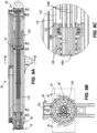
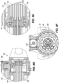
- the boom 30 includes an intermediate rotary actuator or shaft support 102 and a rotary flow distributor 106 ( FIG. 8C ).
- the shaft support 102 is positioned within the housing 42.
- the shaft support 102 includes a body and a bearing 114 engaging an inner surface of the housing 42.
- the boom 30 also includes a second bearing 116, which may be a non-contact bearing that prevents metal-on-metal contact in the event the boom deflects beyond a predetermined amount. In other embodiments, the second bearing may be omitted.
- the shaft support 102 includes an outer portion 110 and an inner portion 134 ( FIG. 6 ). The outer portion 110 engages the housing 42, while the inner portion 134 engages the shaft 46.
- the shaft 46 supports therein trombone tubes 130, which provide passages that communicate between the ends of the boom 30 (for example, between the flow distributor 82 and the carrier 54).
- these passages may carry fluids (e.g., hydraulic fluid), or wired connections.
- a torque tube 119 may be positioned between the trombone tubes 130 and the shaft 46, to resist torsional stress from the shaft 46 to inhibit the torque from breaking or overly stressing the trombone tubes 130.
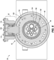
- the shaft support 102 includes a guide member (e.g., a guide pin 109) that extends radially away from the shaft support 102.
- a guide member e.g., a guide pin 109
- the overall profile of the housing 42 is key-shaped to facilitate proper orientation of the shaft support 102 relative to the housing 42, and limit the rotational movement of the shaft support 102 relative to the housing 42.
- the housing 42 includes a portion 48 having a circular profile, and a portion 52 that is positioned radially outward of the portion 48.
- the radially outward portion 52 may have a rectangular profile.
- the shaft support 102 includes a portion having a circular profile positioned within the portion 48 of the housing 42 having a circular profile and locates the shaft 46 within the housing 42.
- the guide pin 109 is connected to a spherical bearing 115 positioned within the portion 52 of the housing 42 having a rectangular profile.
- a hydraulic cylinder 103 (is positioned adjacent the portion 52 and includes a rod end 104 coupled to the guide member 109 (e.g., by a yoke 112). Actuation of the hydraulic cylinder 103 moves the guide pin 109 along at least a portion of the housing 42 in a direction parallel to the axis 60.
- the trombone tubes 130 do not rotate relative to the housing 42, and the tubes 130 are positioned within a torque member (e.g., torque tube 119).
- the torque tube 119 is connected to the outer portion of the shaft support 110 and to an inner portion of the shaft 46.
- the torque tube 119 may be formed as multiple portions.
- the flow distributor 106 ( FIG. 8C ) is positioned proximate a distal end 74 of the shaft 46 and includes an inner portion 106A and an outer portion 106B that rotate relative to one another.
- the outer portion 106A of the flow distributor 106, an outer portion 118 FIG.
- the torque tube 119 may improve accuracy of a sensed boom position in cases in which the movement of the shaft 46 relative to the flow distributor housing is used to monitor the boom position angle (i.e., a sensed position of the flow distributor shaft may more closely reflect the actual angle of the boom).
- Such flexing may be present in other booms in which, for example, interaction between a shaft support and trombone tubes results in the trombone tubes rotating with an inner portion of the shaft support, causing a male portion 130A or female portion 130B of the trombone tubes 130 to flex significantly.
- the shaft support 102 is positioned adjacent the proximal end 70 of the shaft 46 and the flow distributor 106 is positioned adjacent the distal end 74 of the shaft 46. It is understood that this embodiment is one example, and other embodiments may incorporate a different configuration. Also, it is understood that, in other embodiments, the shaft support or the flow distributor may be configured in a reverse manner with respect to connection to the non-rotating first end 50 of the boom 30.
- the inner portion 134 of the shaft support 102 may be coupled to the hydraulic cylinder 103, which causes the axial movement of the shaft 46 and shaft support 102.
- the outer portion 110 may be coupled to the shaft 46.
- the outer portion of the flow distributor 106, the shaft 46, and the outer portion 110 of the shaft support 102 are rotatable in the illustrated embodiment.
- the inner portion of the rotary flow distributor 106, the inner portion 134 of the shaft support 102 (including the torque tube 119 and female portions 130B of the trombone tubes 130), and the guide pin 119 are not rotatable.
- One advantage is that the torque tube 119 can be coupled directly to the inner portion 134 of the shaft support 102 and avoids providing a portion of the torque tube 119 passing through the shaft support 102.
- Cables or wires may carry control power and communications signals between the fixed (i.e., the first end 50) and the extending portions (i.e., the distal end 74) of the boom 30.
- the cables or wires remain the same length while the boom 30 axially extends and retracts, but there may be limited space within the boom 30 to house extra length of cable or wire when the boom 30 is in a retracted state.
- the boom 30 may include a cable guide chain 131.
- FIG. 10 illustrates the shaft 46 in a retracted position relative to the first end 50
- FIG. 11 illustrates the shaft 46 in an extended position.
- the cable guide chain 131 may include a plurality of links coupled to the cable, and the links of the cable guide chain 131 can bend/flex in a controlled manner within the boom 30.
- One end of the cable guide chain 131 is connected to a tube 132 (i.e., one of the trombone tubes 130) that carries the cables or wires from a connection point 133 to the inside of the shaft 46.
- Another end of the cable guide chain 131 is connected at a connection point 135 to a portion of the boom 30 that extends, for example, an inside wall of the shaft 46. This allows the cables or wires to be guided by the cable guide chain 131 in a controlled manner and extend and retract within the shaft 46 free from damage.
- the cable guide chain 131 manages the cables or wires to minimize the risk of tangling, twisting, shearing, or other damage.
- the cable guide chain 131 may be supported within a guide bracket 137 ( FIG. 12 ).
- the guide bracket 137 extends alongside the trombone tubes 130.
- the guide bracket 137 retains the cable guide chain 131 to control the position of the cable guide chain 131 as the shaft 46 extends and retracts and minimizes the risk that the cable guide chain 131 will twist or catch on another structure.
- FIG. 13 illustrates a portion of a cable 139 extending from the connection point 135.
- the cable 139 is guided from the shaft 46 into a slip ring 141 within the flow distributor 106 to be connected to equipment at the distal end 74 of the shaft 46.
- FIGS. 14 to 17 illustrate a device and method for coupling the guide member 109 to the shaft support 102.
- the guide member 109 transmits large forces between the housing 42 and the shaft support 102.
- the guide member 109 may be coupled to the shaft support 102 with an interference fit to prevent excessive movement and wear between the interface of the guide member 109 and shaft support 102, while also facilitating removal/replacement of the guide member 109 as needed without requiring complicated disassembly (e.g., removing the shaft support 102).
- the guide member 119 is coupled to the shaft support 102 by a wedge-shaped protrusion 205 secured within a wedge-shaped pocket 207.
- the wedge-shaped protrusion is positioned on the guide member 109 and the wedge-shaped pocket 207 is positioned on the shaft support 102; it is understood that, in other embodiments, the coupling may be accomplished in a different manner.
- the wedge-shaped protrusion 205 is positioned within the wedge-shaped pocket 207 and retained therein by drive bolts 215 that engage the shaft support 102 from the first end 50.
- the drive bolts 215 draw the guide member 109 into the wedge-shaped pocket 207 to provide an interference fit.
- the guide member 109 is further fixed into the wedge-shaped pocket 207 via a retaining block 210 that, when tightened against the shaft support 102 with retaining block bolts 270, interferes with the wedge-shaped protrusion 205 to hold the guide member 109 against the shaft support 102.
- the retaining block bolts 270, the retaining block 210, and drive bolts 215 are removed, and the guide member 109 can be tapped out of the wedge-shaped pocket 207 to disengage the interference fit between the protrusion 205 and the wedge-shaped pocket 207.
- the guide member 109 can be easily removed from the wedge-shaped pocket 207, without requiring a time-consuming and expensive process for accessing and servicing the guide pin.
- the shaft support 102 may be provided with a hydraulic cylinder along the central axis of the boom 30 that operates to extend the shaft 46 from an extension cylinder 142.
- the housing 42 is shown in broken lines to better illustrate these features.
- the extension cylinder 142 passes though the shaft support 102.
- the flow distributor 106 is positioned at the first end 50, and the flow distributor 106 is connected to the extension cylinder 142.
- the shaft support 102 is slidably connected to the extension cylinder 142 and is connected to the shaft 46.
- the extension cylinder 142 operates to extend or retract the shaft support 102 and shaft 46 ( FIG. 19 ) and extend the shaft support 102 and shaft 46 ( FIG.
- FIG. 20 illustrates cylinder guide grooves 172, which are the rotational connection between the extension cylinder 142 and the shaft 46.
- the cylinder guide grooves 172 are provided on opposite exterior walls of the extension cylinder 142 (i.e., the cylinder guide grooves 172 are diametrically opposed) to interface with a protrusion (not shown) on an interior wall of the shaft 46 such that the shaft 46 is axially slidable relative to the extension cylinder 142, but is not rotatable relative to the extension cylinder 142.
- the cylinder guide grooves and the corresponding protrusions may be configured in another manner.
- trombone tubes 130 are provided within the shaft 46 and extension cylinder 142.
- male portions 130D ( FIG. 21E ) of the trombone tubes are positioned in the extension cylinder 142, and one end of each male portion 130D is received in an associated female portion 130C positioned within the shaft 46.
- male trombone tubes 130D could be positioned within the shaft 46 for insertion into female trombone tubes 130C in the extension cylinder 142.
- These trombone tubes 130C and 130D provide passages from the first end 50 to the distal end 74 to carry fluids, electrical connections, or the like along the length of the boom 30.
- the cylinder guide grooves 172 secure the extension cylinder 142 against rotation relative to the shaft 46, so that when these components are rotated with the male and female trombone tubes 130C and 130D therein, the trombone tubes 130C and 130D are not subject to twisting or torsional forces.
- guide members are provided on opposite interior walls of the housing 42.
- the guide members include guide tracks 146A, 146B that are diametrically opposed and positioned on the shaft support 102, and guide protrusions positioned on an interior surface of the housing 42 engage the tracks 146A, 146B.
- These guide members secure the shaft support 102 against rotation relative to the housing 42, but allow the shaft support 102 to be slidable relative to the housing 42. It is understood that, in other embodiments, the guide tracks and the corresponding protrusions may be configured in another manner.
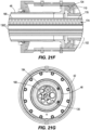
- trombone tubes 130 provide a channel in order to transfer an electronic control signal and control power via a cable 174 (e.g., a spirally coiled cable) from the first end 50 to the distal end 74.
- a cable inner tube 176 houses a straight portion of the cable 174 of a fixed length
- a cable outer tube 178 houses a spirally wound portion of the cable 174 that can stretch by nature of the spiral winding (e.g., by reducing diameter and extending pitch).
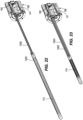
- the cable 174 is connected to a slip ring 182 ( FIG. 22 ) within the flow distributor 106 to provide an electrical connection for both the rotating and non-rotating parts of the boom 30.
- FIGS. 21A and 23 illustrate the cable 174 in a retracted position (e.g., while the distal end of the shaft 46 is retracted with respect to the second end 58 of the housing 42).
- FIGS. 21C and 22 illustrate the cable 174 in an extended position (e.g., while the distal end of the shaft 46 is extended away from the second end 58 of the housing 42).
- FIGS. 21A and 21C differ from FIGS. 22 and 23 in that FIGS. 22 and 23 are illustrated with the shaft 46 removed to more easily show the cable 174 in the trombone tube 130.
- FIGS. 24 and 25 illustrate another embodiment of a boom 30 in retracted ( FIG. 24 ) and extended ( FIG. 25 ) positions.
- An orientation of the cylinder is reversed, and the boom 30 includes guide rods or guide tubes 150.
- male and female trombone tubes 130E and 130F are inserted inside an extension cylinder outer portion 184, pass through an extension cylinder piston 186, and then pass into the extension cylinder inner portion 180.
- the extension cylinder outer portion 184 can be fixed to a rotary actuator (e.g., actuator 82 - see FIG. 4 ) and the trombone tubes 130 provide fluid conduits from a control valve (not shown) that controls the rotation of the rotary actuator 82.
- the outer portion of the shaft support 102 and the outer portion of the flow distributor 106 are rotatably fixed relative to the housing 42.
- Other interior components such as the extension cylinder inner portion 180, extension cylinder piston 186, shaft 46, the inner portion of the shaft support 102, and the inner portion of the flow distributor 106 may be rotatable relative to the housing 42.
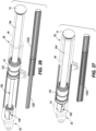
- FIGS. 26 and 27 illustrate the boom 30 of FIGS. 24 and 25 in extended ( FIG. 26 ) and retracted ( FIG. 27 ) positions with the extension cylinder outer portion 184 and the housing 42 shown in broken lines to better illustrate the extension cylinder 180 and the shaft 46.
- Trombone tubes or guide tubes 130F (male) and 130G (female) are shown inset to better illustrate these features within the extension cylinder 180 and the shaft 46.
Landscapes
- Engineering & Computer Science (AREA)
- Mining & Mineral Resources (AREA)
- Geology (AREA)
- Life Sciences & Earth Sciences (AREA)
- General Life Sciences & Earth Sciences (AREA)
- Geochemistry & Mineralogy (AREA)
- Environmental & Geological Engineering (AREA)
- Fluid Mechanics (AREA)
- Physics & Mathematics (AREA)
- Mechanical Engineering (AREA)
- Structural Engineering (AREA)
- Earth Drilling (AREA)
- Drilling And Boring (AREA)
- Conveying And Assembling Of Building Elements In Situ (AREA)
Applications Claiming Priority (1)
| Application Number | Priority Date | Filing Date | Title |
|---|---|---|---|
| US202163241517P | 2021-09-07 | 2021-09-07 |
Publications (2)
| Publication Number | Publication Date |
|---|---|
| EP4144951A1 EP4144951A1 (en) | 2023-03-08 |
| EP4144951B1 true EP4144951B1 (en) | 2024-11-06 |
Family
ID=83232823
Family Applications (1)
| Application Number | Title | Priority Date | Filing Date |
|---|---|---|---|
| EP22194281.6A Active EP4144951B1 (en) | 2021-09-07 | 2022-09-07 | Support for drilling and bolting tool |
Country Status (10)
| Country | Link |
|---|---|
| US (2) | US12025003B2 (pl) |
| EP (1) | EP4144951B1 (pl) |
| AU (1) | AU2022228085A1 (pl) |
| CA (1) | CA3172782A1 (pl) |
| CL (2) | CL2022002428A1 (pl) |
| FI (1) | FI4144951T3 (pl) |
| MX (1) | MX2022011090A (pl) |
| PE (1) | PE20230689A1 (pl) |
| PL (1) | PL4144951T3 (pl) |
| ZA (1) | ZA202209919B (pl) |
Families Citing this family (3)
| Publication number | Priority date | Publication date | Assignee | Title |
|---|---|---|---|---|
| US12057755B2 (en) * | 2020-01-29 | 2024-08-06 | Hougen Manufacturing, Inc. | Electric motor power cord for portable electrical assembly |
| AU2022228085A1 (en) * | 2021-09-07 | 2023-03-23 | Joy Global Underground Mining Llc | Support for drilling and bolting tool |
| CN119507803B (zh) * | 2024-11-22 | 2025-06-24 | 盐城市群力工矿机械有限公司 | 一种轻型坑道钻机 |
Family Cites Families (44)
| Publication number | Priority date | Publication date | Assignee | Title |
|---|---|---|---|---|
| US2581667A (en) | 1946-09-04 | 1952-01-08 | Joy Mfg Co | Mining apparatus |
| US2690896A (en) | 1949-11-10 | 1954-10-05 | Donald E Bissell | Coal drill mount |
| US3061023A (en) | 1958-04-07 | 1962-10-30 | Chicago Pneumatic Tool Co | Shaft jumbo drill apparatus |
| US3172782A (en) | 1960-12-13 | 1965-03-09 | Jache storage battery | |
| US3218893A (en) | 1962-05-22 | 1965-11-23 | Gardner Denver Co | Roof-bolting machine |
| US3207044A (en) | 1963-05-20 | 1965-09-21 | Thomas R Hall | Feeder tube cylinder |
| US3316983A (en) | 1964-10-09 | 1967-05-02 | Louis N Goodman | Earth auger |
| US3439925A (en) | 1965-06-28 | 1969-04-22 | Sp Mfg Corp | Hydraulic cylinder |
| US3404920A (en) | 1966-07-13 | 1968-10-08 | John R. Tabor | Tunneling machine with shield supported traveling excavator |
| US3849995A (en) | 1972-09-06 | 1974-11-26 | Consolidation Coal Co | Method and apparatus for drilling and bolting a mine roof |
| US3840128A (en) | 1973-07-09 | 1974-10-08 | N Swoboda | Racking arm for pipe sections, drill collars, riser pipe, and the like used in well drilling operations |
| US3920084A (en) | 1973-11-21 | 1975-11-18 | Jr Wayne B Russell | Extendable and retractible material delivery devices |
| SE417995B (sv) | 1977-03-03 | 1981-04-27 | Atlas Copco Ab | Bergbultaggregat med gemensam styrning for borrmaskinen och rotationsanordningen for bergbultar |
| SE406209B (sv) | 1977-06-21 | 1979-01-29 | Atlas Copco Ab | Forfaringssett vid borrning i berg och anordning for genomforande av forfarandet |
| ZA777581B (en) | 1977-12-21 | 1979-05-30 | L Herron | Improvements in or relating to rock drilling rigs |
| US4258853A (en) | 1978-04-24 | 1981-03-31 | Caterpillar Tractor Co. | Extensible boom for cranes |
| US4300594A (en) | 1978-07-27 | 1981-11-17 | Bendiberica S.A. | Hydraulic rotary distributor, particularly for power steering mechanisms |
| US4215953A (en) | 1978-08-30 | 1980-08-05 | Envirotech Corporation | Device for injecting cartridges of resin for bolting apparatus |
| US4217987A (en) | 1978-12-01 | 1980-08-19 | Harnischfeger Corporation | Actuator for telescopic boom |
| US4441761A (en) | 1982-01-19 | 1984-04-10 | Fields Rush F | Mining machine |
| SE500903C2 (sv) | 1989-12-20 | 1994-09-26 | Atlas Copco Constr & Mining | Bergborrningsrigg |
| WO1991015655A1 (fr) | 1990-04-03 | 1991-10-17 | Kabushiki Kaisha Komatsu Seisakusho | Excavateur de banc rocheux |
| FI87831C (fi) | 1990-06-28 | 1993-02-25 | Tampella Oy Ab | Vertikal borrningsbom |
| AUPO152596A0 (en) | 1996-08-08 | 1996-08-29 | Cram Australia Pty Ltd | Roofbolter |
| US5954143A (en) | 1998-02-21 | 1999-09-21 | Mccabe; Howard Wendell | Remote controlled all-terrain drill unit |
| AU785234B2 (en) | 2001-04-06 | 2006-11-23 | Minova Australia Pty Limited | Rock bolt installation |
| CA2483434C (en) | 2002-05-03 | 2010-08-24 | Clark Equipment Company | Extendible boom with removable hydraulic hose carrier |
| SE528598C2 (sv) | 2004-10-07 | 2006-12-27 | Atlas Copco Rock Drills Ab | Hölje samt borrigg innefattande ett sådant hölje |
| US20070068583A1 (en) | 2005-09-27 | 2007-03-29 | Johnson Dwight N | Motor-driven hydraulic valve cartridge |
| GB0715754D0 (en) | 2007-08-14 | 2007-09-19 | Delphi Tech Inc | Powered closure device |
| PT2594590E (pt) | 2007-12-14 | 2015-01-14 | Bristol Myers Squibb Co | Moléculas de ligação ao recetor humano ox40 |
| FI121634B (fi) | 2008-05-12 | 2011-02-15 | Sandvik Mining & Constr Oy | Kiertolaite |
| US8622481B2 (en) | 2011-01-25 | 2014-01-07 | Joy Mm Delaware, Inc. | Fiber optic cable protection in a mining system |
| US9580966B2 (en) | 2011-08-24 | 2017-02-28 | Lake Shore Systems, Inc. | All electric powered mobile jumbo drill machine |
| US9791071B2 (en) * | 2013-03-07 | 2017-10-17 | Oshkosh Corporation | Internally supported power track |
| CA2875510A1 (en) | 2014-02-04 | 2015-08-04 | Travis Vogel | Travelling boom for rock bolting machine and apparatus |
| EP3059382B1 (en) | 2015-02-19 | 2017-10-11 | Sandvik Mining and Construction Oy | A mining boom and method of supporting hoses |
| EP3159473B1 (en) | 2015-10-22 | 2018-12-05 | Sandvik Mining and Construction Oy | Rock drilling rig |
| AT520768A5 (de) * | 2016-07-06 | 2023-06-15 | Joy Global Underground Mining Llc | Elektrische Bohr- und Verankerungsvorrichtung |
| CA2960613C (en) | 2016-10-31 | 2019-02-26 | Yves Nelson | Gantry and quick connect mechanism for interchanging drilling and bolting assemblies and method of interchanging bolting assemblies |
| SE542480C2 (en) | 2017-09-08 | 2020-05-19 | Epiroc Rock Drills Ab | Mining or construction vehicle enclosing a conduit arrangement |
| SE541217C2 (en) | 2017-09-08 | 2019-05-07 | Epiroc Rock Drills Ab | Mining or construction vehicle |
| PL3710394T3 (pl) | 2017-12-13 | 2024-06-10 | Joy Global Underground Mining Llc | Podpora narzędzia wiertniczego i wkręcającego |
| AU2022228085A1 (en) * | 2021-09-07 | 2023-03-23 | Joy Global Underground Mining Llc | Support for drilling and bolting tool |
-
2022
- 2022-09-05 AU AU2022228085A patent/AU2022228085A1/en active Pending
- 2022-09-06 CL CL2022002428A patent/CL2022002428A1/es unknown
- 2022-09-06 US US17/903,532 patent/US12025003B2/en active Active
- 2022-09-06 ZA ZA2022/09919A patent/ZA202209919B/en unknown
- 2022-09-06 MX MX2022011090A patent/MX2022011090A/es unknown
- 2022-09-07 EP EP22194281.6A patent/EP4144951B1/en active Active
- 2022-09-07 PE PE2022001933A patent/PE20230689A1/es unknown
- 2022-09-07 PL PL22194281.6T patent/PL4144951T3/pl unknown
- 2022-09-07 FI FIEP22194281.6T patent/FI4144951T3/fi active
- 2022-09-07 CA CA3172782A patent/CA3172782A1/en active Pending
-
2024
- 2024-07-01 US US18/761,219 patent/US12546168B2/en active Active
- 2024-09-23 CL CL2024002840A patent/CL2024002840A1/es unknown
Also Published As
| Publication number | Publication date |
|---|---|
| AU2022228085A1 (en) | 2023-03-23 |
| EP4144951A1 (en) | 2023-03-08 |
| CL2024002840A1 (es) | 2025-01-10 |
| CA3172782A1 (en) | 2023-03-07 |
| US12025003B2 (en) | 2024-07-02 |
| MX2022011090A (es) | 2023-03-08 |
| US20240352798A1 (en) | 2024-10-24 |
| US12546168B2 (en) | 2026-02-10 |
| PE20230689A1 (es) | 2023-04-21 |
| ZA202209919B (en) | 2024-05-30 |
| FI4144951T3 (fi) | 2024-12-19 |
| CL2022002428A1 (es) | 2023-04-14 |
| PL4144951T3 (pl) | 2025-03-31 |
| US20230076602A1 (en) | 2023-03-09 |
Similar Documents
| Publication | Publication Date | Title |
|---|---|---|
| EP4144951B1 (en) | Support for drilling and bolting tool | |
| AU2024202104B2 (en) | Support for drilling and bolting tool | |
| US6880430B2 (en) | Vise apparatus | |
| US8613310B2 (en) | Spooling apparatus for well intervention system | |
| AU2014352890B2 (en) | Planetary gear assembly | |
| EP3059382B1 (en) | A mining boom and method of supporting hoses | |
| US20190078403A1 (en) | Continuous drilling system | |
| US11945681B2 (en) | Expandable reel assembly for a well system | |
| EP2427623B1 (en) | Guiding device for rock drilling machine | |
| EA005479B1 (ru) | Шарнир-вертлюг для бурения скважин |
Legal Events
| Date | Code | Title | Description |
|---|---|---|---|
| PUAI | Public reference made under article 153(3) epc to a published international application that has entered the european phase |
Free format text: ORIGINAL CODE: 0009012 |
|
| STAA | Information on the status of an ep patent application or granted ep patent |
Free format text: STATUS: THE APPLICATION HAS BEEN PUBLISHED |
|
| AK | Designated contracting states |
Kind code of ref document: A1 Designated state(s): AL AT BE BG CH CY CZ DE DK EE ES FI FR GB GR HR HU IE IS IT LI LT LU LV MC MK MT NL NO PL PT RO RS SE SI SK SM TR |
|
| STAA | Information on the status of an ep patent application or granted ep patent |
Free format text: STATUS: REQUEST FOR EXAMINATION WAS MADE |
|
| 17P | Request for examination filed |
Effective date: 20230907 |
|
| RBV | Designated contracting states (corrected) |
Designated state(s): AL AT BE BG CH CY CZ DE DK EE ES FI FR GB GR HR HU IE IS IT LI LT LU LV MC MK MT NL NO PL PT RO RS SE SI SK SM TR |
|
| GRAP | Despatch of communication of intention to grant a patent |
Free format text: ORIGINAL CODE: EPIDOSNIGR1 |
|
| STAA | Information on the status of an ep patent application or granted ep patent |
Free format text: STATUS: GRANT OF PATENT IS INTENDED |
|
| RIC1 | Information provided on ipc code assigned before grant |
Ipc: E21D 20/00 20060101ALI20240430BHEP Ipc: E21B 7/02 20060101AFI20240430BHEP |
|
| INTG | Intention to grant announced |
Effective date: 20240528 |
|
| GRAS | Grant fee paid |
Free format text: ORIGINAL CODE: EPIDOSNIGR3 |
|
| GRAA | (expected) grant |
Free format text: ORIGINAL CODE: 0009210 |
|
| STAA | Information on the status of an ep patent application or granted ep patent |
Free format text: STATUS: THE PATENT HAS BEEN GRANTED |
|
| AK | Designated contracting states |
Kind code of ref document: B1 Designated state(s): AL AT BE BG CH CY CZ DE DK EE ES FI FR GB GR HR HU IE IS IT LI LT LU LV MC MK MT NL NO PL PT RO RS SE SI SK SM TR |
|
| REG | Reference to a national code |
Ref country code: GB Ref legal event code: FG4D |
|
| REG | Reference to a national code |
Ref country code: CH Ref legal event code: EP |
|
| REG | Reference to a national code |
Ref country code: DE Ref legal event code: R096 Ref document number: 602022007419 Country of ref document: DE |
|
| REG | Reference to a national code |
Ref country code: IE Ref legal event code: FG4D |
|
| REG | Reference to a national code |
Ref country code: FI Ref legal event code: FGE |
|
| REG | Reference to a national code |
Ref country code: SE Ref legal event code: TRGR |
|
| P01 | Opt-out of the competence of the unified patent court (upc) registered |
Free format text: CASE NUMBER: APP_63408/2024 Effective date: 20241128 |
|
| REG | Reference to a national code |
Ref country code: LT Ref legal event code: MG9D |
|
| REG | Reference to a national code |
Ref country code: NL Ref legal event code: MP Effective date: 20241106 |
|
| PG25 | Lapsed in a contracting state [announced via postgrant information from national office to epo] |
Ref country code: PT Free format text: LAPSE BECAUSE OF FAILURE TO SUBMIT A TRANSLATION OF THE DESCRIPTION OR TO PAY THE FEE WITHIN THE PRESCRIBED TIME-LIMIT Effective date: 20250306 Ref country code: IS Free format text: LAPSE BECAUSE OF FAILURE TO SUBMIT A TRANSLATION OF THE DESCRIPTION OR TO PAY THE FEE WITHIN THE PRESCRIBED TIME-LIMIT Effective date: 20250306 Ref country code: HR Free format text: LAPSE BECAUSE OF FAILURE TO SUBMIT A TRANSLATION OF THE DESCRIPTION OR TO PAY THE FEE WITHIN THE PRESCRIBED TIME-LIMIT Effective date: 20241106 |
|
| PG25 | Lapsed in a contracting state [announced via postgrant information from national office to epo] |
Ref country code: NL Free format text: LAPSE BECAUSE OF FAILURE TO SUBMIT A TRANSLATION OF THE DESCRIPTION OR TO PAY THE FEE WITHIN THE PRESCRIBED TIME-LIMIT Effective date: 20241106 |
|
| REG | Reference to a national code |
Ref country code: AT Ref legal event code: MK05 Ref document number: 1739529 Country of ref document: AT Kind code of ref document: T Effective date: 20241106 |
|
| PG25 | Lapsed in a contracting state [announced via postgrant information from national office to epo] |
Ref country code: BG Free format text: LAPSE BECAUSE OF FAILURE TO SUBMIT A TRANSLATION OF THE DESCRIPTION OR TO PAY THE FEE WITHIN THE PRESCRIBED TIME-LIMIT Effective date: 20241106 |
|
| PG25 | Lapsed in a contracting state [announced via postgrant information from national office to epo] |
Ref country code: ES Free format text: LAPSE BECAUSE OF FAILURE TO SUBMIT A TRANSLATION OF THE DESCRIPTION OR TO PAY THE FEE WITHIN THE PRESCRIBED TIME-LIMIT Effective date: 20241106 |
|
| PG25 | Lapsed in a contracting state [announced via postgrant information from national office to epo] |
Ref country code: LV Free format text: LAPSE BECAUSE OF FAILURE TO SUBMIT A TRANSLATION OF THE DESCRIPTION OR TO PAY THE FEE WITHIN THE PRESCRIBED TIME-LIMIT Effective date: 20241106 Ref country code: GR Free format text: LAPSE BECAUSE OF FAILURE TO SUBMIT A TRANSLATION OF THE DESCRIPTION OR TO PAY THE FEE WITHIN THE PRESCRIBED TIME-LIMIT Effective date: 20250207 Ref country code: AT Free format text: LAPSE BECAUSE OF FAILURE TO SUBMIT A TRANSLATION OF THE DESCRIPTION OR TO PAY THE FEE WITHIN THE PRESCRIBED TIME-LIMIT Effective date: 20241106 |
|
| PG25 | Lapsed in a contracting state [announced via postgrant information from national office to epo] |
Ref country code: RS Free format text: LAPSE BECAUSE OF FAILURE TO SUBMIT A TRANSLATION OF THE DESCRIPTION OR TO PAY THE FEE WITHIN THE PRESCRIBED TIME-LIMIT Effective date: 20250206 |
|
| PG25 | Lapsed in a contracting state [announced via postgrant information from national office to epo] |
Ref country code: SM Free format text: LAPSE BECAUSE OF FAILURE TO SUBMIT A TRANSLATION OF THE DESCRIPTION OR TO PAY THE FEE WITHIN THE PRESCRIBED TIME-LIMIT Effective date: 20241106 |
|
| PG25 | Lapsed in a contracting state [announced via postgrant information from national office to epo] |
Ref country code: DK Free format text: LAPSE BECAUSE OF FAILURE TO SUBMIT A TRANSLATION OF THE DESCRIPTION OR TO PAY THE FEE WITHIN THE PRESCRIBED TIME-LIMIT Effective date: 20241106 |
|
| PG25 | Lapsed in a contracting state [announced via postgrant information from national office to epo] |
Ref country code: EE Free format text: LAPSE BECAUSE OF FAILURE TO SUBMIT A TRANSLATION OF THE DESCRIPTION OR TO PAY THE FEE WITHIN THE PRESCRIBED TIME-LIMIT Effective date: 20241106 |
|
| PG25 | Lapsed in a contracting state [announced via postgrant information from national office to epo] |
Ref country code: RO Free format text: LAPSE BECAUSE OF FAILURE TO SUBMIT A TRANSLATION OF THE DESCRIPTION OR TO PAY THE FEE WITHIN THE PRESCRIBED TIME-LIMIT Effective date: 20241106 |
|
| PG25 | Lapsed in a contracting state [announced via postgrant information from national office to epo] |
Ref country code: SK Free format text: LAPSE BECAUSE OF FAILURE TO SUBMIT A TRANSLATION OF THE DESCRIPTION OR TO PAY THE FEE WITHIN THE PRESCRIBED TIME-LIMIT Effective date: 20241106 |
|
| PG25 | Lapsed in a contracting state [announced via postgrant information from national office to epo] |
Ref country code: CZ Free format text: LAPSE BECAUSE OF FAILURE TO SUBMIT A TRANSLATION OF THE DESCRIPTION OR TO PAY THE FEE WITHIN THE PRESCRIBED TIME-LIMIT Effective date: 20241106 |
|
| REG | Reference to a national code |
Ref country code: DE Ref legal event code: R097 Ref document number: 602022007419 Country of ref document: DE |
|
| PLBE | No opposition filed within time limit |
Free format text: ORIGINAL CODE: 0009261 |
|
| STAA | Information on the status of an ep patent application or granted ep patent |
Free format text: STATUS: NO OPPOSITION FILED WITHIN TIME LIMIT |
|
| PGFP | Annual fee paid to national office [announced via postgrant information from national office to epo] |
Ref country code: FI Payment date: 20250925 Year of fee payment: 4 |
|
| PGFP | Annual fee paid to national office [announced via postgrant information from national office to epo] |
Ref country code: DE Payment date: 20250929 Year of fee payment: 4 |
|
| PGFP | Annual fee paid to national office [announced via postgrant information from national office to epo] |
Ref country code: NO Payment date: 20250929 Year of fee payment: 4 |
|
| 26N | No opposition filed |
Effective date: 20250807 |
|
| PGFP | Annual fee paid to national office [announced via postgrant information from national office to epo] |
Ref country code: PL Payment date: 20250905 Year of fee payment: 4 |
|
| PGFP | Annual fee paid to national office [announced via postgrant information from national office to epo] |
Ref country code: FR Payment date: 20250925 Year of fee payment: 4 |
|
| PGFP | Annual fee paid to national office [announced via postgrant information from national office to epo] |
Ref country code: SE Payment date: 20250927 Year of fee payment: 4 |
|
| PGFP | Annual fee paid to national office [announced via postgrant information from national office to epo] |
Ref country code: IT Payment date: 20250930 Year of fee payment: 4 |
|
| REG | Reference to a national code |
Ref country code: CH Ref legal event code: H13 Free format text: ST27 STATUS EVENT CODE: U-0-0-H10-H13 (AS PROVIDED BY THE NATIONAL OFFICE) Effective date: 20260425 |