EP4144921B1 - Steinschuh - Google Patents
Steinschuh Download PDFInfo
- Publication number
- EP4144921B1 EP4144921B1 EP22191500.2A EP22191500A EP4144921B1 EP 4144921 B1 EP4144921 B1 EP 4144921B1 EP 22191500 A EP22191500 A EP 22191500A EP 4144921 B1 EP4144921 B1 EP 4144921B1
- Authority
- EP
- European Patent Office
- Prior art keywords
- box
- pile
- rock
- shoe
- rock shoe
- Prior art date
- Legal status (The legal status is an assumption and is not a legal conclusion. Google has not performed a legal analysis and makes no representation as to the accuracy of the status listed.)
- Active
Links
Images


Classifications
-
- E—FIXED CONSTRUCTIONS
- E02—HYDRAULIC ENGINEERING; FOUNDATIONS; SOIL SHIFTING
- E02D—FOUNDATIONS; EXCAVATIONS; EMBANKMENTS; UNDERGROUND OR UNDERWATER STRUCTURES
- E02D5/00—Bulkheads, piles, or other structural elements specially adapted to foundation engineering
- E02D5/72—Pile shoes
-
- E—FIXED CONSTRUCTIONS
- E02—HYDRAULIC ENGINEERING; FOUNDATIONS; SOIL SHIFTING
- E02D—FOUNDATIONS; EXCAVATIONS; EMBANKMENTS; UNDERGROUND OR UNDERWATER STRUCTURES
- E02D5/00—Bulkheads, piles, or other structural elements specially adapted to foundation engineering
- E02D5/22—Piles
- E02D5/24—Prefabricated piles
- E02D5/30—Prefabricated piles made of concrete or reinforced concrete or made of steel and concrete
-
- E—FIXED CONSTRUCTIONS
- E02—HYDRAULIC ENGINEERING; FOUNDATIONS; SOIL SHIFTING
- E02D—FOUNDATIONS; EXCAVATIONS; EMBANKMENTS; UNDERGROUND OR UNDERWATER STRUCTURES
- E02D5/00—Bulkheads, piles, or other structural elements specially adapted to foundation engineering
- E02D5/22—Piles
- E02D5/52—Piles composed of separable parts, e.g. telescopic tubes ; Piles composed of segments
- E02D5/523—Piles composed of separable parts, e.g. telescopic tubes ; Piles composed of segments composed of segments
- E02D5/526—Connection means between pile segments
Definitions
- This invention relates to a rock shoe according to the preamble of claim 1.
- the invention also relates to a pile according to the preamble of claim 7.
- a reinforced concrete pile is always provided with some type of tip protection in order that the concrete would not break from its corners when driven into the soil.
- the concrete piles are brought to a worksite by a lorry and are stored in proximity to the pile-driving site.
- a pile driver is a heavy tracked machine which is to be moved on the worksite as little as possible.
- the piles are generally fetched from a worksite store by hauling them with a long wire to the pile driver, whereby the driven end of the pile is trailed along the ground. The transport of the pile also requires protecting the tip of the pile.
- This so-called rock shoe is conical in shape in such a way that the side of the pile does not hit the inclined rock surface.
- the point part of the rock shoe is formed by a hardened dowel (standard SIS 811192) which has been fastened with a screw to a rigid sleeve welded with reinforcement plates to a bottom plate, a thickness of which is generally of the order of 20 mm.
- Application FI20012026 discloses another way of reinforcing a bottom plate and attaching a point dowel to a shoe structure. This form of reinforcement displaces more of the packed till overlying the rock surface and is therefore easier to become damaged.
- piles of various lengths can often be seen rising from the ground.
- the pile is driven into the soil until at the final strokes it can be shown that it bears the loads according to plan.
- some length of a 12-16 m long standard pile always remains to be cut off.
- the driven piles can be cast in advance to a shorter length.
- a precast concrete manufacturing plant has these shorter piles in store, because cast concrete requires approximately a month to achieve the final strength without chemical additives.
- the above-described rock shoe is cast onto the end of the standard pile.
- Swedish standard SIS 811197 from 1973 discloses a retrofittable rock shoe in which the standard point structure has been attached to a tall box which is wedged to a lower end of a standard pile.
- the rock shoe is exposed to considerable forces during installation of the pile both in a vertical and lateral direction, and these forces tend to break the end of the concrete pile.
- Pile-driving guidelines P02016 disclose the Finnish test requirements in part 2, chapter 3.9.4.
- the problem with a retrofittable rock shoe is the clearance remaining between the box of the rock shoe and the pile, which clearance is required in order that the box could be installed to the end of the pile.
- Concrete piles were manufactured for a long time outside in large battery moulds having side plates fastened to a bottom plate at regular intervals (Peter Alheid: Seminar paper: Betongp ⁇ lar i Sverige, interior picture on page 7, pile seminar 2014). One had to be able to move on top of the mould e.g. by using planks, and the steel reinforcements and steel parts were installed between the side plates.
- a rock shoe to be retrofitted to a ready-made pile is disclosed in publication WO 2007/080217 , Fig. 6.
- a collar made from a thin plate engages the surface of a concrete pile by means of depressions made in the steel plate.
- a shock wave is reflected back from the tip of the pile as a tension wave which the joint between the rock shoe and the pile must be able to transmit.
- a required minimum value of resistance to the tensile force in the joint can be considered to be a yield force of 320 kN (corresponds to a mass of 32 tonnes) of the anchor rods of Swedish standard SIS 811196 (4 anchor rods d 16 material Ks40). It is clear that considering the manufacturing tolerances, the depressions as described in the application cannot transmit such tensile force.
- Application FI 20185944 discloses a rock shoe fastened to a splice of a standard pile (Fig. 6).
- the application does not disclose a possible box of the rock shoe.
- the idea is to join a rock shoe to a regular splice, thus reducing storage need of the precast concrete manufacturing plant.
- the support wedges 203 of the rock shoe (support reinforcements under a bottom plate) are arranged in such a way that they support both of the structure of the rock shoe and the components of the joint system.
- the locking forces are transmitted via locking members, in the standard rock shoe the bottom plate is reinforced in a diagonal direction. In the solution, the reinforcement plate transmitting the driving forces from the point 202 to the pile 100 cannot be located at the lock housing 41.
- the soil material overlying the rock surface is generally packed till, and when piles are test driven into the soil and removed for testing, there is often a strong layer of till remaining between the reinforcements, which has bent the reinforcement plates.
- the lock structure is located unprotected in a critical position exposed to considerable forces from the oblique rock surface and from the hard layer of soil overlying it.
- the locking structure is furthermore located outside the corrosion-protective concrete structure, so designing must be done with rust allowance (min. 2 mm / side) or with non-rusting lock parts, which would mean for standard piles, regardless of whether a point was joined to them or not, significant additional cost due to the material.
- Document RU 186 633 U1 discloses a rock shoe comprising a box, into which the end of the pile is insertable, and a clamping ring arranged around the box for clamping the box against sides of the pile.
- the object of this invention is to provide an improved rock shoe and a pile equipped with the rock shoe.
- the objective according to the invention is achieved with a rock shoe according to claim 1 and with a reinforced concrete pile according to claim 7.
- the rock shoe according to the invention comprises a bottom plate, to a front surface of which a point part has been attached, and a box attached to the bottom plate, into which box the end of a reinforced concrete pile is insertable. Further, the rock shoe comprises a clamping ring arranged around the box for clamping the box against sides of the pile. Joint members have been fastened to the bottom plate for fastening the rock shoe to a joint part at the end of the pile.
- the invention provides significant advantages.
- the rock shoe according to the invention is easily connectable to the end of a pile. Thereby the number of standard piles to be kept in store may be reduced.
- the rock shoe according to the invention may be brought to the worksite and joined to the end of the pile on the site.
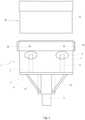
- Fig. 1 and 2 show a rock shoe 1 according to one embodiment of the invention, which rock shoe is fixable to an end of a reinforced concrete pile 20 for example by gluing or by means of joint members.
- the pile may be square or rectangle shaped in cross-section.
- the end of the pile 20 may be equipped with a joint part 21 to which the rock shoe 1 is fixable.
- the rock shoe 1 may be fastened directly to the end of the pile 20 without the joint part 21, for example by gluing.
- the pile comprises reinforcement bars in a longitudinal direction of the pile, for example deformed bars, which are normally located in the concrete at corners of the pile.
- the rock shoe 1 comprises a bottom plate 2, a back surface 3 of which is arranged against the end of the concrete pile to which the rock shoe 1 is to be fastened.
- the rock shoe 1 further comprises a point part 5 attached to a front surface 4 of the bottom plate 2.
- Support wedges 17 supporting the point part 5 have further been attached to the front surface 4 of the bottom plate 2.
- the rock shoe 1 is made from steel.
- Joint members 6 have been fastened to the bottom plate 2 for fastening the rock shoe 1 to the joint part 21 of the end of the pile.
- the joint members 6 are located on an opposite side of the bottom plate 2 relative to the point part 5.
- a first end of the joint member 6 has been joined to the bottom plate 2 for example by welding.
- a second end of the joint member 6 is fixable to the joint part of the end of the pile, e.g. to a pile splice.
- the joint part 21 may comprise a locking member to which the second end of the joint member 6 is fitted and fastened.
- the rock shoe 1 also comprises a collar-type box 7 extending away from the back surface 3 of the bottom plate 2.
- the box 7 is in cross-section of the same shape as the end of the pile, but is in internal diameter larger than the end of the pile.
- the box 7 encloses the joint members 6.
- the height of the box 7 may be greater than the length of the joint members 6.
- a first end of the box 7 has been fastened to the back surface or to the edges of the bottom plate 2.
- the box 7 is open at its second end, whereby the end of the pile may be inserted into the box 7.
- the first end of the box 7, i.e. the end to be fastened to the bottom plate is open.
- the internal diameters of the box 7 are larger than the end of the pile, whereby the end of the pile is insertable in the box 7.
- the empty spaces and/or weld holes of the box 7 may be filled with stiff material, for example petroleum jelly, preventing moisture from spreading inside the box 7.
- openings 9 Through the sides of the box 7 there are openings 9 through which the position of the joint members 6 may be monitored and the joint members 6 guided in such a way that the joint members 6 fit the joint part 21 of the end of the pile when the pile is lowered onto the rock shoe 1.
- the openings 9 are located in alignment with the second ends of the joint members 6.
- the openings 9 may be located at corners of the box 7. In case the rock shoe 1 is glued to the end of the pile 20, excess glue may exit through the openings 9.
- the empty spaces at the corners of the box 7 may be filled with a filling material, for example grouting mortar, epoxy glue etc. The filling material may be fed into the box 7 through the openings 9.
- the corners of the box 7 may be partly open.
- the open corner portions 18 extend from the second end of the box 7 towards the first end.
- the open corner portions 18 make the box 7 more flexible, whereby the sides of the box 7 may be clamped against the sides of the pile.
- the rock shoe 1 comprises a clamping ring 10 for clamping/pressing the box 7 against sides of the pile either directly or indirectly, for example by means of shims 11.
- the clamping ring 10 has been arranged around the box 7, typically at the second end of the box 7.
- the clamping ring 10 has been positioned at the open corner portions 18 of the box 7.
- the length of the open corner portions 18 of the box 7 is greater, typically 1-3 cm greater, than the height of the clamping ring 10.
- the clamping ring 10 is placed around the box 7 at the second end of the box 7.
- the clamping ring 10 comprises screw holes 19, whereby the clamping ring 10 has been fastened to the box 7 by means of screws, for example self-drilling screws.
- a clearance Between the clamping ring 10 and the box 7 on each side there is a clearance, the extent of which is typically 2-3 mm.
- Shims 11 may be inserted in the clearances, which shims press the box 7 against the sides of the pile.
- a lower edge of the shims 11 may also be made wedge-shaped for example by grinding.
- the shims 11 may be driven into the clearances with a hammer.
- the clamping ring 10 may be driven onto the wedge-shaped shims 11 for example with a small sledgehammer.
- the rock shoe 1 may be provided with a clamping ring 10 according to Fig. 3-5 .
- the box 7 shown in Fig. 3 may be like that of the embodiment of Fig. 1 and 2 .
- the bottom plate 2, the point part 5, the support wedges 17 and/or the joint members 6 of the rock shoe 1 of Fig. 3 may be like those of the embodiment of Fig. 1 and 2 .
- the clamping ring 10 comprises four clamping parts 12. One clamping part 12 has been arranged against each side of the box 7. The clamping parts 12 have been attached to each other at each corner of the box 7.
- middle part 12.1 In the middle of the clamping part 12 there is a middle part 12.1 arranged against the side of the box.
- the middle part 12.1 is straight.
- the middle part 12.1 is shorter than the side of the box 7 against which the middle part 12.1 is arranged.
- end parts 12.2 which are inclined relative to the middle part 12.1.
- the end parts 12.2 are directed away from the box 7.
- the end parts 12.2 are at an obtuse angle ⁇ , for example at an angle ⁇ of 120-160 degrees relative to the middle part 12.1.
- the clamping parts 12 on adjacent sides of the box 7 are attached to each other by the end parts 12.2.
- the ends of adjacent end parts 12.2 abut against each other.
- a clamping screw 14 is inserted through the holes 13 of adjacent end parts 12.2. Nuts 15 are screwed onto both ends of the clamping screw 14. Between the nut 15 and the end part 12.2 there is a washer 16. When the nuts 15 are tightened, the end parts 12.2 abut against each other. The obliquity of the clamping screw 14 relative to the washers 16 may be adjusted by changing the length of the end parts 12.2, by placing an additional plate between ends of the end parts 12.2 and/or by using a washer 16 which is thicker or thinner from the side towards the end of the end part 12.2 than from the opposite side towards the middle part 12.1. The nuts 15 are first tightened in such a way that the clearances are removed. Thereby, at each corner of the box 7, there are openings of approximately the same size between the end parts 12.2. Finally, the nuts 15 are tightened to a desired tightening torque for example with a torque wrench.
- the inner surfaces of the box 7 and the end of the pile 20 are cleaned. If necessary, dirt, for example dried laitance etc., is removed for example with a wire brush.
- a layer of mortar or glue may be arranged on the inner surfaces of the box 7.
- the rock shoe 1 is installed with a jack to the end of the pile in a horizontal position, while supporting the other end of the pile.
- the rock shoe 1 On a worksite, the rock shoe 1 is installed in a vertical position.
- the rock shoe 1 is supported for example with the installation box (bottom plate, side plates and support blocks) to the vertical position and the pile is dropped for example by a pile driver into the box 7 of the rock shoe.
- the sides of the box 7 are clamped against the sides of the pile with the clamping ring 10 in the above-described manner.
- the empty spaces at the corners of the box 7 may be filled with a filling material, for example grouting mortar, epoxy glue etc.
- the filling material is fed into the box 7 through the openings 9 on the sides.
Landscapes
- Engineering & Computer Science (AREA)
- Structural Engineering (AREA)
- Life Sciences & Earth Sciences (AREA)
- General Life Sciences & Earth Sciences (AREA)
- Mining & Mineral Resources (AREA)
- Paleontology (AREA)
- Civil Engineering (AREA)
- General Engineering & Computer Science (AREA)
- Piles And Underground Anchors (AREA)
Claims (7)
- Steinschuh (1), der mit einem Ende eines Stahlbetonpfahls (20) auf der Baustelle mittels Verbindungsbauteilen (6) verbunden werden soll, wobei der Steinschuh (1) einen Kasten (7), in den das Ende des Pfahls (20) eingesetzt werden kann, und einen um den Kasten (7) herum angeordneten Klemmring (10) zum Festklemmen des Kastens (7) gegen Seiten des Pfahls (20) umfasst, dadurch gekennzeichnet, dass der Steinschuh eine Bodenplatte (2) umfasst, wobei an einer vorderen Oberfläche (4) derselben ein spitzer Teil (5) angebracht wurde, und an welcher Bodenplatte (2) der Kasten (7) angebracht ist, und wobei Verbindungsbauteile (6) an der Bodenplatte (2) zum Befestigen des Steinschuhs (1) an einem Verbindungsteil (21) an dem Ende des Pfahls (20) befestigt wurden.
- Steinschuh (1) nach Anspruch 1, dadurch gekennzeichnet, dass der Klemmring (10) vier Klemmteile (12) umfasst, die gegen Seiten des Kastens (7) angeordnet und aneinander an Ecken des Kastens (7) angebracht sind.
- Steinschuh (1) nach Anspruch 2, dadurch gekennzeichnet, dass in der Mitte des Klemmteils (12) ein grader Mittelteil (12.1) gegen eine Seite des Kastens (7) angeordnet ist, sich an beiden Enden des Klemmteils (12) Endteile (12.2) befinden, die relativ zu dem Mittelteil (12.1) geneigt sind, und die Klemmteile (12) auf den benachbarten Seiten des Kastens (7) durch die Endteile (12.2) aneinander angebracht wurden.
- Steinschuh (1) nach Anspruch 1, dadurch gekennzeichnet, dass der Klemmring (10) an den Seiten des Kastens (7) mit Schrauben befestigt wurde, und sich zwischen dem Klemmring (10) und den Seiten des Kastens (7) Spalte befinden, in die Beilagscheiben (11) eingesetzt wurden.
- Steinschuh (1) nach einem der vorhergehenden Ansprüche, dadurch gekennzeichnet, dass die Ecken des Kastens (7) teilweise offen sind, und der Klemmring (10) an den offenen Eckbereichen (18) angeordnet wurde.
- Steinschuh (1) nach einem der vorhergehenden Ansprüche, dadurch gekennzeichnet, dass sich auf der Seite des Kastens (7) Öffnungen (9) zur Überwachung der Position der Verbindungsbauteile (6) und/oder zum Leiten der Verbindungsbauteile (6) und/oder zum Entfernen von überschüssigem Klebstoff von dem Kasten (7) und/oder zum Hinzufügen von Klebstoff oder Mörtel in den Kasten (7) befinden.
- Stahlbetonpfahl (20), dessen eines Ende mit einem Verbindungsteil (21) ausgestattet ist, dadurch gekennzeichnet, dass der Steinschuh (1) nach einem der vorhergehenden Ansprüche 1-6 an dem Ende des Pfahls (20) befestigt wurde, wobei der Klemmring (10) um den Kasten (7) des Steinschuhs (1) herum zum Klemmen des Kastens (7) gegen Seiten des Pfahls (20) angeordnet wurde.
Applications Claiming Priority (1)
| Application Number | Priority Date | Filing Date | Title |
|---|---|---|---|
| FIU20214092U FI13042Y1 (fi) | 2021-09-02 | 2021-09-02 | Kalliokärki |
Publications (3)
| Publication Number | Publication Date |
|---|---|
| EP4144921A1 EP4144921A1 (de) | 2023-03-08 |
| EP4144921B1 true EP4144921B1 (de) | 2025-02-19 |
| EP4144921C0 EP4144921C0 (de) | 2025-02-19 |
Family
ID=78475468
Family Applications (1)
| Application Number | Title | Priority Date | Filing Date |
|---|---|---|---|
| EP22191500.2A Active EP4144921B1 (de) | 2021-09-02 | 2022-08-22 | Steinschuh |
Country Status (3)
| Country | Link |
|---|---|
| EP (1) | EP4144921B1 (de) |
| FI (1) | FI13042Y1 (de) |
| PL (1) | PL4144921T3 (de) |
Family Cites Families (8)
| Publication number | Priority date | Publication date | Assignee | Title |
|---|---|---|---|---|
| FI85901C (fi) * | 1989-09-08 | 1993-03-02 | Leimet Oy | Bergsko |
| US6039298A (en) * | 1997-09-12 | 2000-03-21 | Stier; Peter | Tapered steel post |
| FI20012026L (fi) | 2001-10-19 | 2003-04-20 | Emeca Oy | Teräsputkipaalun kalliokärki |
| FI118185B (fi) | 2002-03-01 | 2007-08-15 | Lujabetoni Oy | Betonipaalun levykenkä |
| FI20060013A0 (fi) | 2006-01-09 | 2006-01-09 | Lujabetoni Oy | Menetelmä jälkiasennettavan kärkiosan liittämiseksi teräsbetonipaaluun ja teräsbetonipaalun kärkirakenne |
| WO2020009867A1 (en) * | 2018-07-02 | 2020-01-09 | Origin Point Brands, Llc | Post support having extensive angular adjustability |
| RU186633U1 (ru) * | 2018-07-12 | 2019-01-28 | Дмитрий Владимирович Коровин | Свая забивная |
| FI128431B (fi) | 2018-11-07 | 2020-05-15 | Leimet Oy | Paaluliitos |
-
2021
- 2021-09-02 FI FIU20214092U patent/FI13042Y1/fi active IP Right Grant
-
2022
- 2022-08-22 PL PL22191500.2T patent/PL4144921T3/pl unknown
- 2022-08-22 EP EP22191500.2A patent/EP4144921B1/de active Active
Also Published As
| Publication number | Publication date |
|---|---|
| EP4144921A1 (de) | 2023-03-08 |
| FI13042Y1 (fi) | 2021-10-25 |
| EP4144921C0 (de) | 2025-02-19 |
| PL4144921T3 (pl) | 2025-06-23 |
Similar Documents
| Publication | Publication Date | Title |
|---|---|---|
| US6264402B1 (en) | Method and apparatus for forming piles in place | |
| US5707180A (en) | Method and apparatus for forming piles in-situ | |
| US4911582A (en) | Concrete replacement wall and method of constructing the wall | |
| AU2004101058A4 (en) | Earth Retention and Piling Systems | |
| WO2005005752A1 (de) | Gründung für bauwerke | |
| KR100467170B1 (ko) | 보강토옹벽 축조공법 | |
| KR100657655B1 (ko) | 지반안정공법용 조립식 파일 | |
| KR100933220B1 (ko) | 보강토 옹벽의 배부름 현상에 대한 보수 및 보강방법과이에 사용되는 소일네일 구조체 | |
| EP4144921B1 (de) | Steinschuh | |
| KR200201561Y1 (ko) | 강관파일 두부보강구조 | |
| JP7557984B2 (ja) | 既存工場における鉄骨柱脚の固定方法およびそれが適用された建屋 | |
| KR102760401B1 (ko) | 토목 기초공사용 흙막이 벽체 시공방법 | |
| AU763775B2 (en) | Method and apparatus for forming piles in place | |
| JP3867839B2 (ja) | カルバートのせん断補強方法 | |
| JP3768220B2 (ja) | 橋脚工法及び橋脚 | |
| EP1046753B1 (de) | Verfahren und Vorrichtung zum Herstellen von Ortbetonpfählen im Boden | |
| KR20020066608A (ko) | 강재말뚝과 콘크리트기초와의 보강결합을 위한 결합구 및이를 이용한 결합구조 | |
| KR100728743B1 (ko) | 파형강판 콘크리트 교량 | |
| US7351013B2 (en) | Unitary pile jacking sleeve for installing and compressively loading piling without overhead access and without disrupting a super-structure | |
| JP2005256571A (ja) | 連続壁体とその構築方法 | |
| CA2264197C (en) | Method and apparatus for forming piles in place | |
| KR101217488B1 (ko) | 기초파일 연장구조 | |
| KR102051386B1 (ko) | 휨 및 전단성능이 보강된 고강도 콘크리트파일에 두부보강용 강관캡이 구비된 파일 시공 방법 | |
| JP6905813B2 (ja) | 合成セグメント及びリング体 | |
| KR102685846B1 (ko) | Phc 파일용 두부 보강캡 |
Legal Events
| Date | Code | Title | Description |
|---|---|---|---|
| PUAI | Public reference made under article 153(3) epc to a published international application that has entered the european phase |
Free format text: ORIGINAL CODE: 0009012 |
|
| STAA | Information on the status of an ep patent application or granted ep patent |
Free format text: STATUS: THE APPLICATION HAS BEEN PUBLISHED |
|
| AK | Designated contracting states |
Kind code of ref document: A1 Designated state(s): AL AT BE BG CH CY CZ DE DK EE ES FI FR GB GR HR HU IE IS IT LI LT LU LV MC MK MT NL NO PL PT RO RS SE SI SK SM TR |
|
| STAA | Information on the status of an ep patent application or granted ep patent |
Free format text: STATUS: REQUEST FOR EXAMINATION WAS MADE |
|
| 17P | Request for examination filed |
Effective date: 20230906 |
|
| RBV | Designated contracting states (corrected) |
Designated state(s): AL AT BE BG CH CY CZ DE DK EE ES FI FR GB GR HR HU IE IS IT LI LT LU LV MC MK MT NL NO PL PT RO RS SE SI SK SM TR |
|
| GRAP | Despatch of communication of intention to grant a patent |
Free format text: ORIGINAL CODE: EPIDOSNIGR1 |
|
| STAA | Information on the status of an ep patent application or granted ep patent |
Free format text: STATUS: GRANT OF PATENT IS INTENDED |
|
| RIC1 | Information provided on ipc code assigned before grant |
Ipc: E02D 5/30 20060101ALI20240920BHEP Ipc: E02D 5/52 20060101ALI20240920BHEP Ipc: E02D 5/72 20060101AFI20240920BHEP |
|
| INTG | Intention to grant announced |
Effective date: 20241002 |
|
| GRAS | Grant fee paid |
Free format text: ORIGINAL CODE: EPIDOSNIGR3 |
|
| GRAA | (expected) grant |
Free format text: ORIGINAL CODE: 0009210 |
|
| STAA | Information on the status of an ep patent application or granted ep patent |
Free format text: STATUS: THE PATENT HAS BEEN GRANTED |
|
| AK | Designated contracting states |
Kind code of ref document: B1 Designated state(s): AL AT BE BG CH CY CZ DE DK EE ES FI FR GB GR HR HU IE IS IT LI LT LU LV MC MK MT NL NO PL PT RO RS SE SI SK SM TR |
|
| RAP1 | Party data changed (applicant data changed or rights of an application transferred) |
Owner name: ANSTAR OY |
|
| REG | Reference to a national code |
Ref country code: GB Ref legal event code: FG4D |
|
| REG | Reference to a national code |
Ref country code: CH Ref legal event code: EP |
|
| REG | Reference to a national code |
Ref country code: IE Ref legal event code: FG4D |
|
| REG | Reference to a national code |
Ref country code: DE Ref legal event code: R096 Ref document number: 602022010735 Country of ref document: DE |
|
| U01 | Request for unitary effect filed |
Effective date: 20250221 |
|
| U07 | Unitary effect registered |
Designated state(s): AT BE BG DE DK EE FI FR IT LT LU LV MT NL PT RO SE SI Effective date: 20250228 |
|
| PG25 | Lapsed in a contracting state [announced via postgrant information from national office to epo] |
Ref country code: RS Free format text: LAPSE BECAUSE OF FAILURE TO SUBMIT A TRANSLATION OF THE DESCRIPTION OR TO PAY THE FEE WITHIN THE PRESCRIBED TIME-LIMIT Effective date: 20250519 |
|
| PG25 | Lapsed in a contracting state [announced via postgrant information from national office to epo] |
Ref country code: ES Free format text: LAPSE BECAUSE OF FAILURE TO SUBMIT A TRANSLATION OF THE DESCRIPTION OR TO PAY THE FEE WITHIN THE PRESCRIBED TIME-LIMIT Effective date: 20250219 |
|
| PG25 | Lapsed in a contracting state [announced via postgrant information from national office to epo] |
Ref country code: IS Free format text: LAPSE BECAUSE OF FAILURE TO SUBMIT A TRANSLATION OF THE DESCRIPTION OR TO PAY THE FEE WITHIN THE PRESCRIBED TIME-LIMIT Effective date: 20250619 |
|
| PG25 | Lapsed in a contracting state [announced via postgrant information from national office to epo] |
Ref country code: HR Free format text: LAPSE BECAUSE OF FAILURE TO SUBMIT A TRANSLATION OF THE DESCRIPTION OR TO PAY THE FEE WITHIN THE PRESCRIBED TIME-LIMIT Effective date: 20250219 |
|
| PG25 | Lapsed in a contracting state [announced via postgrant information from national office to epo] |
Ref country code: GR Free format text: LAPSE BECAUSE OF FAILURE TO SUBMIT A TRANSLATION OF THE DESCRIPTION OR TO PAY THE FEE WITHIN THE PRESCRIBED TIME-LIMIT Effective date: 20250520 |
|
| U20 | Renewal fee for the european patent with unitary effect paid |
Year of fee payment: 4 Effective date: 20250815 |
|
| PG25 | Lapsed in a contracting state [announced via postgrant information from national office to epo] |
Ref country code: SM Free format text: LAPSE BECAUSE OF FAILURE TO SUBMIT A TRANSLATION OF THE DESCRIPTION OR TO PAY THE FEE WITHIN THE PRESCRIBED TIME-LIMIT Effective date: 20250219 |
|
| PGFP | Annual fee paid to national office [announced via postgrant information from national office to epo] |
Ref country code: NO Payment date: 20250821 Year of fee payment: 4 |
|
| PG25 | Lapsed in a contracting state [announced via postgrant information from national office to epo] |
Ref country code: CZ Free format text: LAPSE BECAUSE OF FAILURE TO SUBMIT A TRANSLATION OF THE DESCRIPTION OR TO PAY THE FEE WITHIN THE PRESCRIBED TIME-LIMIT Effective date: 20250219 |
|
| PG25 | Lapsed in a contracting state [announced via postgrant information from national office to epo] |
Ref country code: SK Free format text: LAPSE BECAUSE OF FAILURE TO SUBMIT A TRANSLATION OF THE DESCRIPTION OR TO PAY THE FEE WITHIN THE PRESCRIBED TIME-LIMIT Effective date: 20250219 |
|
| PLBE | No opposition filed within time limit |
Free format text: ORIGINAL CODE: 0009261 |
|
| STAA | Information on the status of an ep patent application or granted ep patent |
Free format text: STATUS: NO OPPOSITION FILED WITHIN TIME LIMIT |
|
| PGFP | Annual fee paid to national office [announced via postgrant information from national office to epo] |
Ref country code: PL Payment date: 20251113 Year of fee payment: 4 |
|
| 26N | No opposition filed |
Effective date: 20251120 |