EP4144645B1 - Hubunterstützungssystem in einem flugzeugsitz - Google Patents
Hubunterstützungssystem in einem flugzeugsitz Download PDFInfo
- Publication number
- EP4144645B1 EP4144645B1 EP22167941.8A EP22167941A EP4144645B1 EP 4144645 B1 EP4144645 B1 EP 4144645B1 EP 22167941 A EP22167941 A EP 22167941A EP 4144645 B1 EP4144645 B1 EP 4144645B1
- Authority
- EP
- European Patent Office
- Prior art keywords
- seat
- seat pan
- rails
- aircraft
- lift
- Prior art date
- Legal status (The legal status is an assumption and is not a legal conclusion. Google has not performed a legal analysis and makes no representation as to the accuracy of the status listed.)
- Active
Links
Images


Classifications
-
- B—PERFORMING OPERATIONS; TRANSPORTING
- B64—AIRCRAFT; AVIATION; COSMONAUTICS
- B64D—EQUIPMENT FOR FITTING IN OR TO AIRCRAFT; FLIGHT SUITS; PARACHUTES; ARRANGEMENT OR MOUNTING OF POWER PLANTS OR PROPULSION TRANSMISSIONS IN AIRCRAFT
- B64D11/00—Passenger or crew accommodation; Flight-deck installations not otherwise provided for
- B64D11/06—Arrangements of seats, or adaptations or details specially adapted for aircraft seats
- B64D11/0639—Arrangements of seats, or adaptations or details specially adapted for aircraft seats with features for adjustment or converting of seats
- B64D11/064—Adjustable inclination or position of seats
-
- B—PERFORMING OPERATIONS; TRANSPORTING
- B60—VEHICLES IN GENERAL
- B60N—SEATS SPECIALLY ADAPTED FOR VEHICLES; VEHICLE PASSENGER ACCOMMODATION NOT OTHERWISE PROVIDED FOR
- B60N2/00—Seats specially adapted for vehicles; Arrangement or mounting of seats in vehicles
- B60N2/02—Seats specially adapted for vehicles; Arrangement or mounting of seats in vehicles the seat or part thereof being movable, e.g. adjustable
- B60N2/0224—Non-manual adjustments, e.g. with electrical operation
- B60N2/0244—Non-manual adjustments, e.g. with electrical operation with logic circuits
- B60N2/0256—Arrangements for facilitating the occupant to get in or out of the vehicle, e.g. stowing a seat forward
Definitions
- EP 3 315 409 relate to aircraft seats.
- US 2010/032994 relates to a seat articulation mechanism.
- the aircraft seat is disclosed, in accordance with one or more embodiments of the disclosure.
- the aircraft seat is provided in claim 1 and includes a base assembly couplable to a floor of an aircraft.
- the aircraft seat includes a seat frame coupled to the base assembly, the seat frame including a seat pan frame and a seatback frame, the seat comprising a seat pan coupled to the seat pan frame, the seat pan including one or more fixed seat pan rails, the seat pan configured to couple to a seat pan cushion, the seatback frame configured to couple to a seatback cushion.
- the aircraft seat includes a lift assist system configured to position the seat pan between one or more positions.
- the lift assist system includes one or more pivoting lift rails configured to couple to the one or more fixed seat pan rails.
- the lift assist system includes an actuator sub-system, the actuator sub-system comprising an actuator configured to actuate the one or more pivoting lift rails between the one or more positions.
- the actuator sub-system may further include one or more pivots coupled to one or more fixed cross seat pan rails, the one or more pivots configured to couple the actuator to the one or more pivoting lift rails.
- the actuator may be configured to actuate the seat pan frame between a stowed position and a deployed position by lifting the one or more pivoting lift rails a predetermined distance to cause the seat pan frame to lift the predetermined distance.
- the actuator may be configured to apply an amount of force in an upward direction to the one or more fixed cross seat pan rails to cause the one or more pivoting lift rails to lift the predetermined distance to cause the seat pan frame to lift the predetermined distance.
- the aircraft seat may further include a control panel communicatively coupled to an aircraft controller, the control panel coupled to the actuator sub-system to cause the actuator sub-system to actuate the one or more pivoting lift rails a predetermined distance.
- the actuator may include an electro-mechanical actuator.
- the actuator may be configured to actuate the seat pan frame between a stowed position and a deployed position by lifting the one or more pivoting lift rails a predetermined distance to cause the seat pan frame to lift the predetermined distance when the seat pan cushion and the seatback cushion are separated a select distance.
- the aircraft seat may further include a control panel communicatively coupled to an aircraft controller, the control panel coupled to the translation sub-system to cause the translation sub-system to translate the seat pan frame the select distance away from the seatback frame.
- a letter following a reference numeral is intended to reference an embodiment of the feature or element that may be similar, but not necessarily identical, to a previously described element or feature bearing the same reference numeral (e.g., 1, 1a, 1b).
- reference numeral e.g. 1, 1a, 1b
- Such shorthand notations are used for purposes of convenience only and should not be construed to limit the disclosure in any way unless expressly stated to the contrary.
- any reference to “one embodiment” or “some embodiments” means that a particular element, feature, structure, or characteristic described in connection with the embodiment is included in at least one embodiment disclosed herein.
- the appearances of the phrase “in some embodiments” in various places in the specification are not necessarily all referring to the same embodiment, and embodiments may include one or more of the features expressly described or inherently present herein, or any combination of or sub-combination of two or more such features, along with any other features which may not necessarily be expressly described or inherently present in the instant disclosure.
- FIGS. 1-10C in general illustrate a lift assist system for an aircraft seat, in accordance with one or more embodiments of the disclosure.
- the lift assist system should be configured to lift a seat pan of the aircraft seat to assist the passenger when getting up from the aircraft seat.
- the lift assist system should meet aviation guidelines and/or standards.
- FIG. 1 in general illustrates an aircraft cabin 100 including an aircraft seat 102, in accordance with one or more embodiments of the disclosure.
- the aircraft seat 102 may include, but is not limited to, a business class or first-class passenger seat, an economy-class passenger seat, a crew member seat, or the like. It is noted the terms “aircraft seats” and “passenger seats” may be considered equivalent, for purposes of the disclosure.
- the aircraft seat 102 may include a seatback 104.
- the aircraft seat 102 may include a seat pan 106.
- the aircraft seat 102 may include one or more arms 108.
- the aircraft seat 102 may be coupled to a base 110.
- the base 110 may be covered by a shroud 112.
- the shroud 112 may include one or more sections configured to cover at least a portion of the aircraft seat 102.
- the shroud 112 may include a bucket shroud section and a base shroud section. It is noted, however, that the shroud 112 may be formed from one piece (i.e., includes a single section).
- the seatback 104 may include a headrest 114.
- the headrest 114 may be integrated within the seatback 104.
- the headrest 114 may be a separate component coupled to (or inserted into) the seatback 104.
- the headrest 114 may be movable relative to the seatback frame of the aircraft seat 102 (e.g., adjustable, removable, or the like).
- the seat pan 106 may be coupled to the seatback 104, such that actuation of one may cause a corresponding actuation of the other.
- the seat pan 106 may be coupled to the seatback 104 via one or more pivot joints.
- the seatback 104 may be configured to rotate about an axis through a pivot joint coupling the seatback 104 and the seat pan 106 during actuation between the upright position and the lie-flat or bed position.
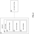
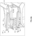
- the aircraft seat 102 may include a seat frame 200.
- the seat frame 200 includes at least a seatback frame 202, a seat pan frame 204, and a base assembly 206.
- One or more of the seatback frame 202 and/or the seat pan frame 204 may be directly coupled, or indirectly coupled via one or more interconnecting components, to one or more components of the seat frame 200. At least a portion of the shroud 112 (e.g., the bucket shroud section of the shroud 112) may be configured to cover the seat pan frame 204.
- the base assembly 206 may include one or more base rails 300 (e.g., tubes, bars, or the like).
- the one or more base rails 300 may be positioned relative to a particular direction of travel of the aircraft seat 102 including, but not limited to, perpendicular (e.g., cross-wise), parallel (e.g., cross-wise), or the like.
- the one or more base rails 300 may be positioned relative to a same or a different direction of travel of the aircraft seat 102.
- the base assembly 206 may include one or more base brackets 302.
- the one or more base rails 300 may be coupled together via the one or more base brackets 302.
- a base bracket 302 may couple together the base rail 300 and an adjacent base rail 300 at any angle, such that the base assembly 206 may include an outline of any geometric shape known in the art.
- the outline may be rectangular or substantially rectangular. Therefore, the above description should not be interpreted as a limitation on the present disclosure but merely an illustration.
- the one or more base brackets 302 may be coupled to a set of floor tracks of the aircraft cabin 100 (e.g., as illustrated in FIG. 1 ) via one or more floor fittings 304. At least a portion of the shroud 112 (e.g., the base shroud section of the shroud 112) may be configured to cover the base assembly 206.
- FIGS. 2 -9C illustrate a lift assist system 208 for an aircraft seat 102, in accordance with one or more embodiments of the disclosure. It is noted that the description of the various embodiments, components, and operations described previously herein with respect to the aircraft seat 102 should be interpreted to extend to the system 208, and vice versa.
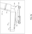
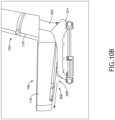
- the aircraft seat 102 includes a lift assist system 208. It is noted that the lift assist system 208 may be adapted and mounted in any orientation to cater to various aircraft seat base designs and requirements.
- the lift assist system 208 is configured to lift the seat pan 106 of the aircraft seat 102 to assist the passenger while getting up.
- the lift assist system 208 may be configured to couple to a portion of the seat pan frame 204 of the aircraft seat 102.
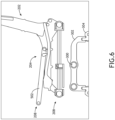
- the lift assist system 208 includes one or more pivoting lift rails 500 configured to couple to one or more fixed seat pan rails 502.
- a seat pan cushion 116 of the seat pan 106 may be configured to couple to the seat pan frame 204.
- the seat pan cushion 116 may be configured to couple to the one or more pivoting lift rails 500 and the one or more fixed seat pan rails 502.
- the one or more pivoting lift rails 500 when the one or more pivoting lift rails 500 are actuated (as discussed further herein), the one or more pivoting lift rails 500 may be configured to cause the seat pan cushion 116, coupled to the one or more fixed seat pan rails 502, to lift a predetermined distance to assist the passenger when getting up.
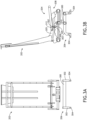
- the lift assist system 208 includes an actuator subsystem 308.
- the actuator sub-system 308 includes an actuator 309.
- the actuator may include, but is not limited to, a piston 307 (movable portion of the actuator) and a body/chassis 310 (fixed portion of the actuator) configured to actuate the one or more pivoting lift rails 500 between one or more positions.
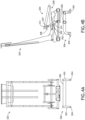
- the piston 307 may be configured to actuate the one or more pivoting lifts rails 500 between a stowed (or normal) position, as shown in FIGS. 3A-3B , to a deployed (or lifted) position, as shown in FIGS.
- the one or more pivoting lift rails 500 may be configured to actuate a seat pan 106 and/or a seat pan cushion 116 (without causing the seatback 104 and/or seatback cushion 118 to actuate) between the stowed position and the deployed position, and vice versa, by actuating the one or more pivoting lift rails 500.
- the actuator sub-system 308 may be installed on any location of the seat frame 200.
- the piston 307 may be coupled to the pivot 312 and the body/chassis 310 may be coupled via a pivot to the seat frame 205.
- the piston 307 may be coupled to the pivot 312 and the body/chassis 310 may be coupled via a pivot 311 to the seat frame 205.
- the actuator sub-system 308 may be configured to couple to the one or more pivoting lift rails 500 via one or more pivots 312.
- the one or more pivots 312 may be coupled to one or more fixed cross rails 504 coupled to the one or more pivoting lift rails 500.
- the actuator sub-system 308 may apply an amount of force to the one or more fixed cross rails 504 to cause the one or more pivoting lift rails 500 to lift a predetermined distance which then causes the seat pan cushion 116 to lift, without lifting the seatback cushion 118 and/or seatback frame 202.
- the lifting of the seat pan cushion 116 a predetermined distance via the one or more pivoting lift rails 500 and the actuator sub-system 308, provides the passenger assistance when they are getting up from the aircraft seat 102.
- the actuator sub-system 308 may include any type of actuator known in the art including, but not limited to, one or more electro-mechanical actuators, gas spring actuators, linear/rotary actuators, or the like. It is noted that for purposes of simplicity, the actuator sub-system 308 and/or one or more components of the actuator sub-system 308 are not depicted in FIGS. 7A -9C, as such FIGS. 7A -9C are provided merely for illustrative purposes and shall not be construed as limiting the scope of the present disclosure. Further, although FIGS. 3A-4C depict a specific actuator sub-system configuration, it is noted that the actuator sub-system 308 may be configured in any manner suitable for lifting one or more components of the lift assist system, as such FIGS. 3A-4C are provided merely for illustrative purposes and shall not be construed as limiting the scope of the present disclosure.
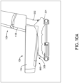
- the lift assist system 208 includes a translation sub-system 800 configured to translate the seat pan 106.
- the translation sub-system 800 may be configured to translate the seat pan 106 including the seat pan cushion 116 in a forward direction away from the seatback 104, such that the seat pan cushion 116 does not overlap with the seatback cushion 118 and/or seatback frame 202.
- the seat pan 106 may be actuated without actuating the seatback 104 and/or seatback cushion 118 of the aircraft seat 102. It is noted that the independent actuation of the seat pan 106 and/or seat pan cushion 116 is a space saving mechanism.
- the independent actuation does not require too much space surrounding the aircraft seat 102 to operate the lift assist system 208.
- an ample amount of space surrounding the aircraft seat is needed to operate the system.
- the translation sub-system 800 includes one or more tracking rails 802 positioned between the one or more pivoting lift rails 500 and the one or more fixed seat pan rails 502.
- the one or more tracking rails 802 may be coupled to the one or more pivoting lift rails 500, such that the one or more tracking rails 802 and the one or more pivoting lift rails 500 may translate along the axis of the one or more fixed seat pan rails 502.
- the one or more tracking rails 802 may translate the seat pan cushion 116 a select distance before lifting the seat pan cushion 116, such that the seat pan cushion 116 and the seatback cushion 118 do not overlap, as shown in FIGS. 10A-10C .
- the translation sub-system 800 includes a slot-and-groove assembly configured to translate the seat pan 106.
- the one or more fixed seat pan rails 502 may include one or more grooves 900 and the one or more tracking rails 802, coupled to the one or more pivoting lift rails 500, may include one or more slots 902.
- the one or more tracking rails 802 may translate the seat pan cushion 116 a select distance, via the slot-and-groove assembly.
- the one or more slots 902 may translate along the one or more grooves 900 to translate the seat pan cushion 116 a select distance (e.g., until the seat pan cushion 116 and seatback cushion 118 do not overlap, as shown in FIGS. 10A-10C ).
- the lift assist system 208 may be adjusted electrically.
- the lift assist system 208 may include a control panel 120 for adjusting the lift assist system 208.
- the aircraft seat 102 may include a control panel 120 within a portion of the one or more arm rests 108.
- the control panel 120 may be used to lift the seat pan cushion 116 a select distance.
- the control panel 120 may be used to translate the seat pan cushion 116 a select distance until the seat pan cushion 116 does not overlap with the seatback cushion 118, then the control panel 120 may be used to lift the seatback cushion 118 a select distance.
- the control panel 120 may be coupled to an aircraft controller.
- FIG. 1 depicts the control panel 120 coupled to a portion of the arm rests 108, it is noted that the control panel 120 may be coupled to any portion of the aircraft seat 102 and/or to any portion of the aircraft cabin 100 (e.g., an overhead portion of the aircraft seat 102, an in-flight entertainment device, or the like).
- vertical may be understood as being defined with respect to a z-axis as illustrated in the Figures.
- horizontal may be understood as being defined with respect to an x-axis or a y-axis as illustrated in the Figures.
- the aircraft seat 102 and/or the components of the aircraft seat 102 may be installed within an avionics environment and configured in accordance with aviation guidelines and/or standards put forth by, but not limited to, the Federal Aviation Administration (FAA), the European Aviation Safety Agency (EASA) or any other flight certification agency or organization; the American National Standards Institute (ANSI), Aeronautical Radio, Incorporated (ARINC), the Society of Automotive Engineers (SAE), or any other standards setting organization or company; the Radio Technical Commission for Aeronautics (RTCA) or any other guidelines agency or organization; or the like.
- FAA Federal Aviation Administration
- EASA European Aviation Safety Agency
- ARINC Aeronautical Radio, Incorporated
- SAE Society of Automotive Engineers
- RTCA Radio Technical Commission for Aeronautics
- the lift assist system 208 is not limited to the aircraft seat 102 within the avionics environment and/or the aircraft components within the avionics environment.
- the lift assist system 208 may be configured to operate in any type of vehicle known in the art.
- the vehicle may be any air, space, land, or water-based personal equipment or vehicle; any air, space, land, or water-based commercial equipment or vehicle; any air, space, land, or water-based military equipment or vehicle known in the art.
- the vehicle may include an automobile.
- the lift assist system 208 may be coupled to and/or configured to operate with apparatus sold for commercial or industrial use in either a home or a business. Therefore, the above description should not be interpreted as a limitation on the present disclosure but merely an illustration.
Landscapes
- Engineering & Computer Science (AREA)
- Aviation & Aerospace Engineering (AREA)
- Transportation (AREA)
- Mechanical Engineering (AREA)
- Seats For Vehicles (AREA)
Claims (8)
- Luftfahrzeugsitz (102), umfassend:eine Basisbaugruppe (206), die an einen Boden eines Luftfahrzeugs koppelbar ist;einen Sitzrahmen (200), der an die Basisbaugruppe gekoppelt ist, wobei der Sitzrahmen einen Sitzschalenrahmen (204) und einen Sitzlehnenrahmen (202) beinhaltet, wobei der Sitz eine Sitzschale (106) umfasst, die an den Sitzschalenrahmen (204) gekoppelt ist, wobei die Sitzschale (106) eine oder mehrere feste Sitzschalenschienen (502) beinhaltet, wobei die Sitzschale (106) dazu konfiguriert ist, sich an ein Sitzschalenpolster (116) zu koppeln, wobei der Sitzlehnenrahmen dazu konfiguriert ist, sich an ein Sitzlehnenpolster (118) zu koppeln; undein Hebehilfssystem (208), das dazu konfiguriert ist, die Sitzschale (106) zwischen einer Verstauposition und einer Ausfahrposition in Bezug auf den Sitzschalenrahmen (204) zu positionieren, wobei das Hebehilfssystem umfasst:eine oder mehrere schwenkbare Hebeschienen (500), die dazu konfiguriert sind, sich an die eine oder die mehreren festen Sitzschalenschienen (502) zu koppeln, wobei die eine oder die mehreren schwenkbaren Hebeschienen (500) in der Verstauposition im Wesentlichen parallel zu der einen oder den mehreren festen Sitzschalenschienen (502) angeordnet sind;ein Betätigungselement-Subsystem (308), wobei das Betätigungselement-Subsystem ein Betätigungselement (309) beinhaltet, das dazu konfiguriert ist, die eine oder die mehreren schwenkbaren Hebeschienen (500) zwischen einer von der Verstauposition und der Ausfahrposition zu betätigen; undgekennzeichnet durchein Verschiebungssubsystem (800), wobei das Verschiebungssubsystem umfasst:eine oder mehrere Führungsschienen (802), die zwischen der einen oder den mehreren schwenkbaren Hebeschienen (500) und der einen oder den mehreren festen Sitzschalenschienen (502) positioniert sind; undeine Schlitz- und Nutbaugruppe, die dazu konfiguriert ist, die Sitzschale (106) um eine ausgewählte Entfernung von dem Sitzlehnenrahmen (202) weg zu verschieben, wobei die Schlitzund Nutbaugruppe einen oder mehrere Schlitze (902), die auf der einen oder den mehreren schwenkbaren Hebeschienen (500) positioniert sind, und eine oder mehrere Nuten (900), die auf der einen oder den mehreren Führungsschienen (802) positioniert sind, umfasst, wobei der eine oder die mehreren Schlitze (902) dazu konfiguriert sind, sich entlang der einen oder den mehreren Nuten (900) zu verschieben, um die Sitzschale (106) um die ausgewählte Entfernung von dem Sitzlehnenrahmen (202) weg zu verschieben.
- Luftfahrzeugsitz nach Anspruch 1, wobei das Betätigungselement-Subsystem ferner umfasst:
einen oder mehrere Schwenkpunkte, die an eine oder mehrere feste Quersitzschalenschienen (502) gekoppelt sind, wobei der eine oder die mehreren Schwenkpunkte dazu konfiguriert sind, das Betätigungselement (309) an die eine oder die mehreren schwenkbaren Hebeschienen (500) zu koppeln. - Luftfahrzeugsitz nach Anspruch 2, wobei das Betätigungselement (309) dazu konfiguriert ist, die Sitzschale (106) zwischen der Verstauposition und der Ausfahrposition zu betätigen, indem die eine oder die mehreren schwenkbaren Hebeschienen (500) um eine vorbestimmte Entfernung angehoben werden, um zu bewirken, dass sich die Sitzschale (106) um die vorbestimmte Entfernung anhebt.
- Luftfahrzeugsitz nach Anspruch 3, wobei das Betätigungselement (309) dazu konfiguriert ist, einen Kraftaufwand in einer Aufwärtsrichtung auf die eine oder die mehreren festen Quersitzschalenschienen (502) auszuüben, um zu bewirken, dass sich die eine oder die mehreren schwenkbaren Hebeschienen (500) um die vorbestimmte Entfernung anheben, um zu bewirken, dass sich die Sitzschale (106) um die vorbestimmte Entfernung anhebt.
- Luftfahrzeugsitz nach einem der vorhergehenden Ansprüche, wobei der Luftfahrzeugsitz ferner umfasst:
eine Steuertafel (120), die kommunikativ an eine Flugzeugsteuereinheit gekoppelt ist, wobei die Steuertafel an das Betätigungselement-Subsystem (308) gekoppelt ist, um zu bewirken, dass das Betätigungselement-Subsystem die eine oder die mehreren schwenkbaren Hebeschienen (500) um eine vorbestimmte Entfernung betätigt. - Luftfahrzeugsitz nach einem der vorhergehenden Ansprüche, wobei das Betätigungselement (309) ein elektromechanisches Betätigungselement beinhaltet.
- Luftfahrzeugsitz nach einem der vorhergehenden Ansprüche, wobei das Betätigungselement (309) dazu konfiguriert ist, die Sitzschale (106) zwischen der Verstauposition und der Ausfahrposition zu betätigen, indem die eine oder die mehreren schwenkbaren Hebeschienen (500) um eine vorbestimmte Entfernung angehoben werden, um zu bewirken, dass sich die Sitzschale (106) um die vorbestimmte Entfernung anhebt, wenn das Sitzschalenpolster (116) und das Sitzlehnenpolster (118) um eine ausgewählte Entfernung getrennt sind.
- Luftfahrzeugsitz nach einem der vorhergehenden Ansprüche, wobei der Luftfahrzeugsitz ferner umfasst:
eine Steuertafel (120), die kommunikativ an eine Flugzeugsteuereinheit gekoppelt ist, wobei die Steuertafel an das Verschiebungssubsystem (800) gekoppelt ist, um zu bewirken, dass das Verschiebungssubsystem (800) die Sitzschale (106) um die ausgewählte Entfernung von dem Sitzlehnenrahmen (202) weg verschiebt.
Applications Claiming Priority (2)
| Application Number | Priority Date | Filing Date | Title |
|---|---|---|---|
| IN202141039810 | 2021-09-02 | ||
| US17/501,223 US11814178B2 (en) | 2021-09-02 | 2021-10-14 | Lift assist system for an aircraft seat |
Publications (2)
| Publication Number | Publication Date |
|---|---|
| EP4144645A1 EP4144645A1 (de) | 2023-03-08 |
| EP4144645B1 true EP4144645B1 (de) | 2024-11-27 |
Family
ID=81307486
Family Applications (1)
| Application Number | Title | Priority Date | Filing Date |
|---|---|---|---|
| EP22167941.8A Active EP4144645B1 (de) | 2021-09-02 | 2022-04-12 | Hubunterstützungssystem in einem flugzeugsitz |
Country Status (1)
| Country | Link |
|---|---|
| EP (1) | EP4144645B1 (de) |
Family Cites Families (6)
| Publication number | Priority date | Publication date | Assignee | Title |
|---|---|---|---|---|
| SG54502A1 (en) * | 1997-02-20 | 1998-11-16 | Singapore Airlines Ltd | Improvements in transport accommodation |
| GB0706775D0 (en) * | 2007-04-05 | 2007-05-16 | Premium Aircraft Interiors Uk | Aircraft seat |
| EP2313316B1 (de) * | 2008-08-05 | 2012-05-09 | BE Aerospace, Inc. | Gelenkmechanismus für einen sitz |
| US9114731B2 (en) * | 2009-07-15 | 2015-08-25 | Toyota Shatai Kabushiki Kaisha | Vehicle seat |
| CA2927115C (en) * | 2013-10-21 | 2018-07-10 | B/E Aerospace, Inc. | Independently articulating seat pan for aircraft seat |
| EP3315409B1 (de) * | 2016-10-28 | 2020-06-24 | B/E Aerospace, Inc. | Flugzeugsitz mit insassengewichtserfassungsmechanismus zum einstellen der kipp-anlehnkraft |
-
2022
- 2022-04-12 EP EP22167941.8A patent/EP4144645B1/de active Active
Also Published As
| Publication number | Publication date |
|---|---|
| EP4144645A1 (de) | 2023-03-08 |
Similar Documents
| Publication | Publication Date | Title |
|---|---|---|
| EP4101765B1 (de) | Flugzeugsitz | |
| EP3453620B1 (de) | Gleitunterlageanordnung für flugzeugsitz | |
| CN106965937B (zh) | 可展开的门安装式座椅 | |
| US11299274B1 (en) | Aircraft passenger compartment with an accessibility door | |
| US11613361B2 (en) | Vertical adjustment system for an aircraft seat | |
| EP4079636B1 (de) | Höhenverstellmechanismus für einen flugzeugsitz | |
| EP4053018A1 (de) | Ausziehbare armlehne mit automatischen einzugsmerkmalen | |
| EP4410672A1 (de) | Bildschirmstoppvorrichtung | |
| EP3626619A1 (de) | Mehrstufiges sitzlehnenverlängerungssystem | |
| EP3889045A1 (de) | Flugzeugsitz mit ausziehbarem und zurückziehbarem rückteil | |
| EP3626618B1 (de) | Dynamisches rückhaltesystem für einen flugzeugsitz | |
| EP4249377B1 (de) | Rücklehnmechanismus für die armlehne eines passagiersitzes | |
| EP4108566B1 (de) | Wagenanordnung mit überlastungsschutz | |
| US11814178B2 (en) | Lift assist system for an aircraft seat | |
| EP4144645B1 (de) | Hubunterstützungssystem in einem flugzeugsitz | |
| CN113525691B (zh) | 具有弹簧辅助致动的飞机座椅 | |
| EP4011776B1 (de) | Federbasierte sitzmembran | |
| EP4186749B1 (de) | Anordnung zur schnellen entfernung einer kopfstütze | |
| EP4600152A1 (de) | Flugzeugsitzbasisverfolgungssystem | |
| US20250100691A1 (en) | Pilot seat assembly with integrated rest position | |
| US20250256850A1 (en) | Aircraft seat base tracking system | |
| EP4311773A1 (de) | Bewegungssteuerungssystem für einen flugzeugsitz | |
| EP4311774B1 (de) | Schienensystem für einen flugzeugsitz | |
| US12522361B2 (en) | Recline lockout device for aircraft seat | |
| US20250353598A1 (en) | Modular power box mounting system |
Legal Events
| Date | Code | Title | Description |
|---|---|---|---|
| PUAI | Public reference made under article 153(3) epc to a published international application that has entered the european phase |
Free format text: ORIGINAL CODE: 0009012 |
|
| STAA | Information on the status of an ep patent application or granted ep patent |
Free format text: STATUS: THE APPLICATION HAS BEEN PUBLISHED |
|
| AK | Designated contracting states |
Kind code of ref document: A1 Designated state(s): AL AT BE BG CH CY CZ DE DK EE ES FI FR GB GR HR HU IE IS IT LI LT LU LV MC MK MT NL NO PL PT RO RS SE SI SK SM TR |
|
| STAA | Information on the status of an ep patent application or granted ep patent |
Free format text: STATUS: REQUEST FOR EXAMINATION WAS MADE |
|
| 17P | Request for examination filed |
Effective date: 20230906 |
|
| RBV | Designated contracting states (corrected) |
Designated state(s): AL AT BE BG CH CY CZ DE DK EE ES FI FR GB GR HR HU IE IS IT LI LT LU LV MC MK MT NL NO PL PT RO RS SE SI SK SM TR |
|
| P01 | Opt-out of the competence of the unified patent court (upc) registered |
Effective date: 20230922 |
|
| GRAP | Despatch of communication of intention to grant a patent |
Free format text: ORIGINAL CODE: EPIDOSNIGR1 |
|
| STAA | Information on the status of an ep patent application or granted ep patent |
Free format text: STATUS: GRANT OF PATENT IS INTENDED |
|
| RIC1 | Information provided on ipc code assigned before grant |
Ipc: B60N 2/24 20060101ALI20240624BHEP Ipc: B60N 2/02 20060101ALI20240624BHEP Ipc: B64D 11/06 20060101AFI20240624BHEP |
|
| INTG | Intention to grant announced |
Effective date: 20240716 |
|
| GRAS | Grant fee paid |
Free format text: ORIGINAL CODE: EPIDOSNIGR3 |
|
| GRAA | (expected) grant |
Free format text: ORIGINAL CODE: 0009210 |
|
| STAA | Information on the status of an ep patent application or granted ep patent |
Free format text: STATUS: THE PATENT HAS BEEN GRANTED |
|
| AK | Designated contracting states |
Kind code of ref document: B1 Designated state(s): AL AT BE BG CH CY CZ DE DK EE ES FI FR GB GR HR HU IE IS IT LI LT LU LV MC MK MT NL NO PL PT RO RS SE SI SK SM TR |
|
| REG | Reference to a national code |
Ref country code: GB Ref legal event code: FG4D |
|
| REG | Reference to a national code |
Ref country code: CH Ref legal event code: EP |
|
| REG | Reference to a national code |
Ref country code: IE Ref legal event code: FG4D |
|
| REG | Reference to a national code |
Ref country code: DE Ref legal event code: R096 Ref document number: 602022008064 Country of ref document: DE |
|
| REG | Reference to a national code |
Ref country code: LT Ref legal event code: MG9D |
|
| REG | Reference to a national code |
Ref country code: NL Ref legal event code: MP Effective date: 20241127 |
|
| PG25 | Lapsed in a contracting state [announced via postgrant information from national office to epo] |
Ref country code: PT Free format text: LAPSE BECAUSE OF FAILURE TO SUBMIT A TRANSLATION OF THE DESCRIPTION OR TO PAY THE FEE WITHIN THE PRESCRIBED TIME-LIMIT Effective date: 20250327 Ref country code: IS Free format text: LAPSE BECAUSE OF FAILURE TO SUBMIT A TRANSLATION OF THE DESCRIPTION OR TO PAY THE FEE WITHIN THE PRESCRIBED TIME-LIMIT Effective date: 20250327 Ref country code: HR Free format text: LAPSE BECAUSE OF FAILURE TO SUBMIT A TRANSLATION OF THE DESCRIPTION OR TO PAY THE FEE WITHIN THE PRESCRIBED TIME-LIMIT Effective date: 20241127 |
|
| PG25 | Lapsed in a contracting state [announced via postgrant information from national office to epo] |
Ref country code: FI Free format text: LAPSE BECAUSE OF FAILURE TO SUBMIT A TRANSLATION OF THE DESCRIPTION OR TO PAY THE FEE WITHIN THE PRESCRIBED TIME-LIMIT Effective date: 20241127 Ref country code: NL Free format text: LAPSE BECAUSE OF FAILURE TO SUBMIT A TRANSLATION OF THE DESCRIPTION OR TO PAY THE FEE WITHIN THE PRESCRIBED TIME-LIMIT Effective date: 20241127 |
|
| REG | Reference to a national code |
Ref country code: AT Ref legal event code: MK05 Ref document number: 1745496 Country of ref document: AT Kind code of ref document: T Effective date: 20241127 |
|
| PG25 | Lapsed in a contracting state [announced via postgrant information from national office to epo] |
Ref country code: BG Free format text: LAPSE BECAUSE OF FAILURE TO SUBMIT A TRANSLATION OF THE DESCRIPTION OR TO PAY THE FEE WITHIN THE PRESCRIBED TIME-LIMIT Effective date: 20241127 |
|
| PG25 | Lapsed in a contracting state [announced via postgrant information from national office to epo] |
Ref country code: ES Free format text: LAPSE BECAUSE OF FAILURE TO SUBMIT A TRANSLATION OF THE DESCRIPTION OR TO PAY THE FEE WITHIN THE PRESCRIBED TIME-LIMIT Effective date: 20241127 |
|
| PG25 | Lapsed in a contracting state [announced via postgrant information from national office to epo] |
Ref country code: NO Free format text: LAPSE BECAUSE OF FAILURE TO SUBMIT A TRANSLATION OF THE DESCRIPTION OR TO PAY THE FEE WITHIN THE PRESCRIBED TIME-LIMIT Effective date: 20250227 |
|
| PG25 | Lapsed in a contracting state [announced via postgrant information from national office to epo] |
Ref country code: LV Free format text: LAPSE BECAUSE OF FAILURE TO SUBMIT A TRANSLATION OF THE DESCRIPTION OR TO PAY THE FEE WITHIN THE PRESCRIBED TIME-LIMIT Effective date: 20241127 Ref country code: GR Free format text: LAPSE BECAUSE OF FAILURE TO SUBMIT A TRANSLATION OF THE DESCRIPTION OR TO PAY THE FEE WITHIN THE PRESCRIBED TIME-LIMIT Effective date: 20250228 Ref country code: AT Free format text: LAPSE BECAUSE OF FAILURE TO SUBMIT A TRANSLATION OF THE DESCRIPTION OR TO PAY THE FEE WITHIN THE PRESCRIBED TIME-LIMIT Effective date: 20241127 |
|
| PG25 | Lapsed in a contracting state [announced via postgrant information from national office to epo] |
Ref country code: PL Free format text: LAPSE BECAUSE OF FAILURE TO SUBMIT A TRANSLATION OF THE DESCRIPTION OR TO PAY THE FEE WITHIN THE PRESCRIBED TIME-LIMIT Effective date: 20241127 |
|
| PGFP | Annual fee paid to national office [announced via postgrant information from national office to epo] |
Ref country code: FR Payment date: 20250319 Year of fee payment: 4 |
|
| PG25 | Lapsed in a contracting state [announced via postgrant information from national office to epo] |
Ref country code: RS Free format text: LAPSE BECAUSE OF FAILURE TO SUBMIT A TRANSLATION OF THE DESCRIPTION OR TO PAY THE FEE WITHIN THE PRESCRIBED TIME-LIMIT Effective date: 20250227 |
|
| PG25 | Lapsed in a contracting state [announced via postgrant information from national office to epo] |
Ref country code: SM Free format text: LAPSE BECAUSE OF FAILURE TO SUBMIT A TRANSLATION OF THE DESCRIPTION OR TO PAY THE FEE WITHIN THE PRESCRIBED TIME-LIMIT Effective date: 20241127 |
|
| PGFP | Annual fee paid to national office [announced via postgrant information from national office to epo] |
Ref country code: DE Payment date: 20250319 Year of fee payment: 4 |
|
| PG25 | Lapsed in a contracting state [announced via postgrant information from national office to epo] |
Ref country code: DK Free format text: LAPSE BECAUSE OF FAILURE TO SUBMIT A TRANSLATION OF THE DESCRIPTION OR TO PAY THE FEE WITHIN THE PRESCRIBED TIME-LIMIT Effective date: 20241127 |
|
| PG25 | Lapsed in a contracting state [announced via postgrant information from national office to epo] |
Ref country code: EE Free format text: LAPSE BECAUSE OF FAILURE TO SUBMIT A TRANSLATION OF THE DESCRIPTION OR TO PAY THE FEE WITHIN THE PRESCRIBED TIME-LIMIT Effective date: 20241127 |
|
| PG25 | Lapsed in a contracting state [announced via postgrant information from national office to epo] |
Ref country code: RO Free format text: LAPSE BECAUSE OF FAILURE TO SUBMIT A TRANSLATION OF THE DESCRIPTION OR TO PAY THE FEE WITHIN THE PRESCRIBED TIME-LIMIT Effective date: 20241127 |
|
| PG25 | Lapsed in a contracting state [announced via postgrant information from national office to epo] |
Ref country code: SK Free format text: LAPSE BECAUSE OF FAILURE TO SUBMIT A TRANSLATION OF THE DESCRIPTION OR TO PAY THE FEE WITHIN THE PRESCRIBED TIME-LIMIT Effective date: 20241127 |
|
| PG25 | Lapsed in a contracting state [announced via postgrant information from national office to epo] |
Ref country code: CZ Free format text: LAPSE BECAUSE OF FAILURE TO SUBMIT A TRANSLATION OF THE DESCRIPTION OR TO PAY THE FEE WITHIN THE PRESCRIBED TIME-LIMIT Effective date: 20241127 |
|
| PG25 | Lapsed in a contracting state [announced via postgrant information from national office to epo] |
Ref country code: IT Free format text: LAPSE BECAUSE OF FAILURE TO SUBMIT A TRANSLATION OF THE DESCRIPTION OR TO PAY THE FEE WITHIN THE PRESCRIBED TIME-LIMIT Effective date: 20241127 |
|
| REG | Reference to a national code |
Ref country code: DE Ref legal event code: R097 Ref document number: 602022008064 Country of ref document: DE |
|
| PG25 | Lapsed in a contracting state [announced via postgrant information from national office to epo] |
Ref country code: SE Free format text: LAPSE BECAUSE OF FAILURE TO SUBMIT A TRANSLATION OF THE DESCRIPTION OR TO PAY THE FEE WITHIN THE PRESCRIBED TIME-LIMIT Effective date: 20241127 |
|
| PLBE | No opposition filed within time limit |
Free format text: ORIGINAL CODE: 0009261 |
|
| STAA | Information on the status of an ep patent application or granted ep patent |
Free format text: STATUS: NO OPPOSITION FILED WITHIN TIME LIMIT |
|
| REG | Reference to a national code |
Ref country code: CH Ref legal event code: L10 Free format text: ST27 STATUS EVENT CODE: U-0-0-L10-L00 (AS PROVIDED BY THE NATIONAL OFFICE) Effective date: 20251008 |
|
| 26N | No opposition filed |
Effective date: 20250828 |
|
| REG | Reference to a national code |
Ref country code: CH Ref legal event code: H13 Free format text: ST27 STATUS EVENT CODE: U-0-0-H10-H13 (AS PROVIDED BY THE NATIONAL OFFICE) Effective date: 20251125 |
|
| PG25 | Lapsed in a contracting state [announced via postgrant information from national office to epo] |
Ref country code: LU Free format text: LAPSE BECAUSE OF NON-PAYMENT OF DUE FEES Effective date: 20250412 |
|
| PG25 | Lapsed in a contracting state [announced via postgrant information from national office to epo] |
Ref country code: MC Free format text: LAPSE BECAUSE OF FAILURE TO SUBMIT A TRANSLATION OF THE DESCRIPTION OR TO PAY THE FEE WITHIN THE PRESCRIBED TIME-LIMIT Effective date: 20241127 |
|
| REG | Reference to a national code |
Ref country code: BE Ref legal event code: MM Effective date: 20250430 |
|
| PG25 | Lapsed in a contracting state [announced via postgrant information from national office to epo] |
Ref country code: BE Free format text: LAPSE BECAUSE OF NON-PAYMENT OF DUE FEES Effective date: 20250430 |
|
| PG25 | Lapsed in a contracting state [announced via postgrant information from national office to epo] |
Ref country code: CH Free format text: LAPSE BECAUSE OF NON-PAYMENT OF DUE FEES Effective date: 20250430 |