EP4249377B1 - Rücklehnmechanismus für die armlehne eines passagiersitzes - Google Patents
Rücklehnmechanismus für die armlehne eines passagiersitzes Download PDFInfo
- Publication number
- EP4249377B1 EP4249377B1 EP23163748.9A EP23163748A EP4249377B1 EP 4249377 B1 EP4249377 B1 EP 4249377B1 EP 23163748 A EP23163748 A EP 23163748A EP 4249377 B1 EP4249377 B1 EP 4249377B1
- Authority
- EP
- European Patent Office
- Prior art keywords
- seat
- passenger seat
- seat pan
- armrest
- linkage
- Prior art date
- Legal status (The legal status is an assumption and is not a legal conclusion. Google has not performed a legal analysis and makes no representation as to the accuracy of the status listed.)
- Active
Links
Images


Classifications
-
- B—PERFORMING OPERATIONS; TRANSPORTING
- B64—AIRCRAFT; AVIATION; COSMONAUTICS
- B64D—EQUIPMENT FOR FITTING IN OR TO AIRCRAFT; FLIGHT SUITS; PARACHUTES; ARRANGEMENT OR MOUNTING OF POWER PLANTS OR PROPULSION TRANSMISSIONS IN AIRCRAFT
- B64D11/00—Passenger or crew accommodation; Flight-deck installations not otherwise provided for
- B64D11/06—Arrangements of seats, or adaptations or details specially adapted for aircraft seats
- B64D11/0648—Lower frame constructions
-
- B—PERFORMING OPERATIONS; TRANSPORTING
- B64—AIRCRAFT; AVIATION; COSMONAUTICS
- B64D—EQUIPMENT FOR FITTING IN OR TO AIRCRAFT; FLIGHT SUITS; PARACHUTES; ARRANGEMENT OR MOUNTING OF POWER PLANTS OR PROPULSION TRANSMISSIONS IN AIRCRAFT
- B64D11/00—Passenger or crew accommodation; Flight-deck installations not otherwise provided for
- B64D11/06—Arrangements of seats, or adaptations or details specially adapted for aircraft seats
- B64D11/0639—Arrangements of seats, or adaptations or details specially adapted for aircraft seats with features for adjustment or converting of seats
- B64D11/064—Adjustable inclination or position of seats
-
- B—PERFORMING OPERATIONS; TRANSPORTING
- B64—AIRCRAFT; AVIATION; COSMONAUTICS
- B64D—EQUIPMENT FOR FITTING IN OR TO AIRCRAFT; FLIGHT SUITS; PARACHUTES; ARRANGEMENT OR MOUNTING OF POWER PLANTS OR PROPULSION TRANSMISSIONS IN AIRCRAFT
- B64D11/00—Passenger or crew accommodation; Flight-deck installations not otherwise provided for
- B64D11/06—Arrangements of seats, or adaptations or details specially adapted for aircraft seats
- B64D11/0639—Arrangements of seats, or adaptations or details specially adapted for aircraft seats with features for adjustment or converting of seats
- B64D11/0641—Seats convertible into beds
-
- B—PERFORMING OPERATIONS; TRANSPORTING
- B64—AIRCRAFT; AVIATION; COSMONAUTICS
- B64D—EQUIPMENT FOR FITTING IN OR TO AIRCRAFT; FLIGHT SUITS; PARACHUTES; ARRANGEMENT OR MOUNTING OF POWER PLANTS OR PROPULSION TRANSMISSIONS IN AIRCRAFT
- B64D11/00—Passenger or crew accommodation; Flight-deck installations not otherwise provided for
- B64D11/06—Arrangements of seats, or adaptations or details specially adapted for aircraft seats
- B64D11/0639—Arrangements of seats, or adaptations or details specially adapted for aircraft seats with features for adjustment or converting of seats
- B64D11/0644—Adjustable arm rests
Definitions
- the present invention generally relates to aircraft seating, and more specifically to reclining mechanisms for aircraft seating.
- Business class airline passenger seats are typically adjustable between upright and lie-flat positions to provide passenger comfort and comply with taxi, take-off and landing seating position requirements.
- Such passenger seats typically include a seatback and seat pan, often linked in motion, supported by a frame and angularly adjustable by way of a seat recline mechanism.
- Conventional passenger seats typically include an adjustable or fixed armrest.
- the trend in commercial business class is seats that articulate to form a full flat bed. In the vast majority of the business class seats, as the seat translates forward from upright to a bed mode the armrest does not follow this motion and remains in the same location. This creates a problem because as the seat is moving forward the usable portion of the armrest gets smaller and smaller. Ideally, you want to have armrests that are part of the seat and move with the seat pan.
- US 2020/0047890 A1 describes an aircraft seat including a seat pan, a seat back and an armrest.
- the seat pan is mounted to a seat chassis by a pivoting connection about which the seat pan pivots.
- the seat back and armrest follow a guided movement of the seat pan between a reclined and an upright position.
- the passenger seat includes a seat pan including a housing and bracket fixed to the housing.
- the passenger seat includes a seatback.
- the seat pan and the seatback including a first pivot joint by which the seatback is pivotally connected to the seat pan.
- the passenger seat includes an armrest.
- the armrest includes a brace fixed to the armrest.
- the brace and the seatback including a second pivot joint by which the armrest is pivotally connected to the seatback.
- the passenger seat includes a linkage connected between the seat pan and the armrest.
- the bracket and the linkage including a third pivot joint by which the linkage is pivotally connected to the seat pan.
- the brace and the linkage including a fourth joint by which the linkage is pivotally connected to the armrest.
- the passenger seat is configurable between an upright position and a bed position.
- the linkage is disposed within the housing.
- An angle of the seat pan is adjusted as the passenger seat is configured between the upright position and the bed position.
- the armrest follows the seat pan by the linkage wherein the armrest is automatically raised and lowered by the linkage as the passenger seat is transitioned between the upright position and the bed position.
- the bracket includes a first end and a second end connected to form a u-shape, wherein the first end of the bracket is fixed to the seat pan and wherein the second end of the bracket includes the third pivot joint.
- a letter following a reference numeral is intended to reference an embodiment of the feature or element that may be similar, but not necessarily identical, to a previously described element or feature bearing the same reference numeral (e.g., 1, 1a, 1b).
- reference numeral e.g. 1, 1a, 1b
- Such shorthand notations are used for purposes of convenience only and should not be construed to limit the disclosure in any way unless expressly stated to the contrary.
- any reference to “one embodiment” or “some embodiments” means that a particular element, feature, structure, or characteristic described in connection with the embodiment is included in at least one embodiment disclosed herein.
- the appearances of the phrase “in some embodiments” in various places in the specification are not necessarily all referring to the same embodiment, and embodiments may include one or more of the features expressly described or inherently present herein, or any combination or sub-combination of two or more such features, along with any other features which may not necessarily be expressly described or inherently present in the instant disclosure.
- Embodiments of the present disclosure are generally directed to a passenger seat including an armrest recline mechanism that causes the armrests to follow the seat pan.
- the armrest recline mechanism includes a linkage connecting the armrest with the seat pan, thereby causing the armrest to follow the motion of the seat pan.
- the linkage is constructed such that the armrest is aligned with the seat pan when the passenger seat is in a bed position (also referred to as a lie-flat position). By keeping the armrest aligned with the seat pan, such component may be parallel or substantially parallel (e.g., as parallel as possible) through positions in the translation.
- the linkage also provides smooth kinematic motion for the armrest as the seat transitions between the bed position and an upright position (also referred to as a taxi, takeoff, and landing (TTOL) position).
- the armrest may also maintain an aligned relationship (e.g., substantially parallel) to the seat pan over a portion of the followed motion.
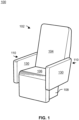
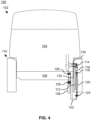
- the passenger seats 102 may be coupled to a floor 109 of an aircraft 100.
- the passenger seat 102 includes a seatback 104 and a seat pan 106.
- the seatback 104 may include an upper portion and a lower portion.
- the passenger seat 102 also includes a spreader 108 (also referred to as a seat support structure, a seat chassis, and the like) that is configured to mount to a floor 109 of the aircraft 100 for providing structural support to various components of the passenger seat 102, such as the seat pan 106 and the seatback 104.
- the spreader 108 may be coupled to the floor 109 by a track (e.g., an anti-rattle track), or the like. Multiple of the spreaders 108 (e.g., a left spreader and a right spreader) may be connected by a transverse tube (not depicted).
- the seatback 104 and the seat pan 106 may be separate structures and/or may include one or more shared components.
- the seatback 104 and the seat pan 106 can have a shared cushion or covering.
- the seatback 104 and the seat pan 106 are configured to move.
- the seatback 104 and the seat pan 106 can be actuated such that the passenger seat 102 is configurable between an upright position and a bed position.
- the passenger seat 102 also includes one or more armrests 110 (e.g., a left armrest and a right armrest).
- the armrest 110 is pivotally connected to the seatback 104.
- the armrest 110 includes a housing 130 which protects a passenger from interacting with components disposed therein.
- the housing 130 of the armrest 110 may include a padded top surface on which the passenger may rest their arms.
- the housing 130 of the armrest 110 may also include a flat face on the interior sides of the passenger seat 102, and may be covered by a number of materials.
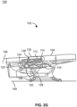
- the passenger seat 102 includes a brace 112, a linkage 120, a bracket 122, and pivot joints (e.g., a pivot joint 114, a pivot joint 118, a pivot joint 124, a pivot joint 126).
- the term pivot joint may also be referred to herein as a pin joint, a revolute joint, or the like.
- Such pivot joints may generally be understood to include one degree of freedom allowing rotation about an axis.
- the pivot joints permit relative rotational motion of the linkage 120 relative to the brace 112, the linkage 120 relative to the bracket 122, and the seat pan 106 relative to the seatback 104.
- the brace 112 may be provided in a rigid arrangement with the armrest 110 and the bracket 122 may be provided in a rigid arrangement with the seat pan 106.
- the seat pan 106 and the seatback 104 including a pivot joint 126 by which the seatback 104 is pivotally connected to the seat pan 106.
- the linkage 120 pivots about the pivot joint 118 with respect to the brace 112 and pivots about the pivot joint 124 with respect to the bracket 122, thereby causing movement of the armrest 110.
- the armrest 110 then pivots with respect to the seatback 104 about the pivot joint 114.
- the relative movements of the rigid bodies about the pivot joint 114, the pivot joint 118, the pivot joint 124, and the pivot joint 126 may be kinematically represented as a four-bar linkage, which may be further coupled to a camming mechanism on the spreader 108 and a recline mechanism between the seat pan 106 and the seatback 104.
- the arrangement of the brace 112, the linkage 120, and the bracket 122 may provide for sufficient rotational motion in combination with the camming mechanism on the spreader 108 and the recline mechanism between the seat pan 106 and the seatback 104, to achieve the upright position and the bed position.
- the armrest 110 includes the brace 112 fixed to the armrest 110.
- the brace 112 may be fixed to the housing 130 of the armrest 110 by a fastener, adhesive, and the like. The brace 112 may then reinforce the armrest 110.
- the brace 112 may be fixed within the armrest 110 such that rotational motion of the brace 112 is imparted to the armrest 110.
- the brace 112 may also include one or more features for coupling the armrest 110 to other components of the passenger seat 102.
- the brace includes a pivot joint 114.
- the pivot joint 114 is provided between the brace 112 and the seatback 104. In this regard, the brace 112 may pivot about the pivot joint 114 relative to the seatback 104.
- the brace 112 may also include a truss member 116 extending downwards from the pivot joint 114.
- the truss member 116 may be joined with the brace 112.
- the truss member 116 may be joined with the brace 112 during fabrication of the truss member 116, such as by injection molding, thermo forming, compression molding, or the like.
- the truss member 116 may be formed as a constituent member of the brace 112.
- the truss member 116 may also be joined with the brace 112 by a fastener or the like.
- the truss member 116 includes a triangular shape.
- the triangular shape of the truss member 116 may include a vertex.
- the truss member 116 may also include a pivot joint 118 disposed proximal to the vertex (e.g., at or offset to the side).
- the pivot joint 118 is provided between the brace 112 and the linkage 120.
- the brace 112 may pivot about the pivot joint 114 relative to the linkage 120.
- the brace 112 may include a number of shapes suitable for the pivot joint 114 and the pivot joint 118.
- the use of the truss member 116 may be advantageous in both providing sufficient strength for pivot joint 118 while also reducing a weight associated with brace 112.
- the passenger seat 102 includes the linkage 120.
- the linkage 120 is connected between the seat pan 106 and the armrest 110.
- the linkage 120 is pivotably connected to the brace 112 at the pivot joint 118, such that the linkage 120 is pivotally connected to the armrest 110.
- the linkage 120 is also be pivotably connected to the bracket 122 at the pivot joint 124, such that the linkage 120 is pivotally connected to the seat pan 106.
- the linkage 120 may transmit motion between the seat pan 106 and the armrest 110 for causing the armrest 110 to rotate and be vertically displaced.
- the linkage 120 may generally include a rigid member for transmitting the motion with minimal bending.
- the use of the u-shape for the bracket 122 may be advantageous for providing the bracket 122 with the ability to receive one or more components of the passenger seat 102, such as, but not limited to, the housing 130 of the armrest 110.
- the bracket 122 may be provided within a hole of the housing 130, reducing a likelihood a passenger accessing the linkage 120 (e.g., a pinch point).
- the spreader 108 may include a guide path 128 which acts as a linear cam.
- linear cam is meant to refer to a cam element which moves in a linear fashion along a slotted hole, a cammed surface, a guide path, or the like.
- the seat pan 106 may include a component, such as a roller, which interfaces with the guide path 128 to follow the guide path 128. Such roller may be in a fixed relation with the pivot joint 126.
- the motive force which configures the passenger seat 102 between the upright position and the bed position may be provided by the guide path 128.
- the guide path 128 may include a first end point and a second end point.
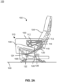
- the first end point of the guide path 128 may correspond to the upright position of the passenger seat 102, such that passenger seat 102 may be in the upright position when the follower of the seat pan 106 is disposed at the first end point, as depicted in FIG. 2A .
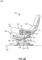
- the second end point may correspond to the bed position of the passenger seat 102, such that passenger seat 102 may be in the bed position when the follower of the seat pan 106 is disposed at the second end point, as depicted in FIG. 2G .
- the seat pan 106 is configured to follow the guide path 128 between the first end point and the second end point as the passenger seat 102 is configured between the upright position and the bed position.
- the seat pan 106 may also configured to follow the guide path 128 between the second end point and the first end point as the passenger seat 102 is configured between the bed position and the seat position.
- the guide path may include one or more angles.
- the guide path may include a first angle, a second angle, and a third angle such that the guide path 128 includes a substantially arcuate shape.
- the first end point of the guide path may be disposed at the first angle and the second end point of the guide path may be disposed at the third angle, with the second angle joining the first angle and the third angle.
- the ends of the guide path 128 may be at a highest vertical point (i.e., the guide path opens upward) with the forward end being slightly higher than the rear ward end. In this arrangement, the rear end of the seat pan 106 is lowest at mid recline to provide a cradling sitting position.
- a passenger seat is described in U.S. Patent No. 9,174,737 , titled "AIRCRAFT SEAT WITH TRANSLATING SEATBACK LINKAGE PIVOT.”
- the arrangement, position, and lengths of the brace 112, the linkage 120, and the bracket 122 is selected to control the surfaces of one or more of the armrest 110, the seatback 104, or the seat pan 106 in one or more of the upright position, the bed position, and/or while translating between the upright position and the bed position.
- FIGS. 2A depicts, the top surface of the armrest being aligned with the floor when the passenger seat is configured in the upright position.
- FIGS. 2A-C depicts the top surface of the armrest including an offset angle from the top surface of the seat pan as the seat pan follows along the first angle and the second angle of the guide path.
- FIGS. 2D-2D further depicts the top surface of the armrest aligned with the top surface of the seat pan as the seat pan.
- FIGS. 2D-2G depicts the top surface of the armrest 110 aligned with the top surface of the seat pan 106 as the seat pan 106 follows along the third angle of the guide path 128. Such alignment may be due to the linkage 120 keeping parallelism between the seat pan 106 and armrest 110.
- FIGS. 2D-2F depicts the top surface of the armrest 110 and the top surface of the seat pan 106 at an offset angle from the floor 109 for a portion of the guide path 128 as the seat pan follows along the third angle of the guide path 128.
- FIG. 2G further depicts the top surface of the armrest 110 and the top surface of the seat pan 106 aligned when the passenger seat is configured in the bed position. This arrangement may be beneficial in providing a flat surface on which a passenger may sleep.
- the arrangement described above thus provides for a smooth transition from the upright position, where the top surface of the seat pan 106 is offset from the armrest 110, to the bed position, where the top surface of the seat pan 106 is aligned with the top surface of the armrest 110.
- the armrest 110 is automatically raised and lowered by the linkage 120 as the passenger seat 102 is transitioned between the upright position and the bed position.
- the passenger does not need to manually raise or lower the armrest 110.
- the armrest 110 may be raised and lowered without requiring an electrical actuator, a hydraulic actuator, or the like.
- the linkage 120 may also be relatively light weight and include minimal translating components.
- the brace 112 the linkage 120, the bracket 122, and a camming surface of the spreader 108 are highlighted for clarity and emphasis, while some portions of the passenger seat 102, e.g., the seatback 104, the seat pan 106, or the armrest 110 are deemphasized. Other portions of the passenger seat 102, e.g., the recline mechanism for the seatback 104, are not shown to avoid confusion and unnecessary detail.
- the recline mechanism for the seatback 104 a linkage coupled between the seat pan 106 and the seatback 104, which motivates the seatback 104 into the bed position as the angle of the seat pan 106 is adjusted.
- Such linkage may include a pivot point in common with the seat pan 106, pivotably coupling the linkage to the seat pan 106.
- the linkage may also include a guide path which the seatback is configured to follow.
- a recline mechanism for a seatback is described in U.S. Patent No. 10,450,072 , titled "SEATBACK ARTICULATION ASSEMBLY AND METHOD.
- the aircraft 100 including a perspective view of the passenger seat 102 in the bed position is described, in accordance with one or more embodiments of the present disclosure.
- the top surface (e.g., the arm pad) of the housing 130 of the armrest 110 may be made to be in substantially the same plane as the top surface (e.g., the seat cushion) of the seat pan 106.
- the top surface of the housing 130 of the armrest 110 may also be made to be in substantially the same plane as the seatback 104.
- the bracket 122 is formed as a u-shape with a first end of the bracket 122 fixed to the seat pan at a location 132 and with a second end including the pivot joint 124.
- the arrangement of the bracket 122 is advantageous in pivotally coupling the linkage 120 to the seat pan 106, while avoiding interference with the housing 130.
- the housing 130 may maintain a flush interior surface, thereby preventing pinching.
- the linkage 120 may be maintained within the housing 130 as the passenger seat 102 transitions between the upright position and the bed position.
- the linkage 120 may be provided within the armrest 110 and cause the armrest to move with the seat pan 106, achieving a desired kinematic motion.
- one or more of the aircraft 100 and the passenger seat 102 may include a passenger control panel.
- the passenger control panel may include a switch (or the like) which may re-position or configure the passenger seat 102 into the bed position.
- the passenger control panel may include a switch (or the like) which may re-position or configure the passenger seat 102 into the upright position.
- the passenger seat 102 may be actuated by engaging a handle that activates one or more mechanical assemblies for configuring the aircraft in the upright position and the bed position. Therefore, the above description should not be interpreted as a limitation on the scope of the disclosure but merely an illustration.
- the term "upright” seating position is used to describe a taxi, take-off and landing compliant seatback configuration
- the term “reclined” seating position is used to describe a seating position in which the seatback is reclined relative to the upright seatback configuration
- the term "lie-flat” position is used to describe a configuration in which the seatback and seat bottom form a substantially flat and continuous surface.
- the passenger seat 102 may be configured in accordance with aviation guidelines and/or standards put forth by, but not limited to: the Federal Aviation Administration (FAA), the European Aviation Safety Agency (EASA), or any other flight certification agency or organization; the American National Standards Institute (ANSI) or any other standards setting organization or company; and the like.
- FAA Federal Aviation Administration
- EASA European Aviation Safety Agency
- ANSI American National Standards Institute
- the passenger seat 102 may be installed within any number of environments.
- the environment may include any type of vehicle known in the art.
- the vehicle may be any air, land, or water-based personal equipment or vehicle; any air, land, or water-based commercial equipment or vehicle; any air, land, or water-based military equipment or vehicle known in the art.
- the environment may include a commercial or industrial establishment (e.g., a home or a business).
- the passenger seat includes the various components described herein on each side of the seat which work in cooperation to adjust the seating position and the armrest position.
Landscapes
- Engineering & Computer Science (AREA)
- Aviation & Aerospace Engineering (AREA)
- Seats For Vehicles (AREA)
Claims (13)
- Passagiersitz (102), umfassend:eine Sitzfläche (106), die eine an der Sitzfläche (106) befestigte Halterung (122) beinhaltet;eine Rückenlehne (104), wobei die Sitzfläche (106) und die Rückenlehne (104) ein erstes Drehgelenk (126) beinhalten, durch das die Rückenlehne (104) schwenkbar mit der Sitzfläche (106) verbunden ist;eine Armlehne (110), die ein Gehäuse (130) und eine an dem Gehäuse (130) befestigte Strebe (112) beinhaltet, wobei die Strebe (112) und die Rückenlehne (104) ein zweites Drehgelenk (114) beinhalten, durch das die Armlehne (110) schwenkbar mit der Rückenlehne (104) verbunden ist; undein Gestänge (120), das zwischen der Sitzfläche (106) und der Armlehne (110) verbunden ist, wobei die Halterung (122) und das Gestänge (120) ein drittes Drehgelenk (124) beinhalten, durch das das Gestänge (120) schwenkbar mit der Sitzfläche (106) verbunden ist, wobei die Strebe (112) und das Gestänge (120) ein viertes Drehgelenk (118) beinhalten, durch das das Gestänge (120) schwenkbar mit der Armlehne (110) verbunden ist, wobei das Gestänge (120) innerhalb des Gehäuses (130) angeordnet ist;wobei der Passagiersitz (102) zwischen einer aufrechten Position und einer Bettposition konfigurierbar ist; wobei ein Winkel der Sitzfläche (106) angepasst wird, wenn der Passagiersitz (102) zwischen der aufrechten Position und der Bettposition konfiguriert wird;wobei die Armlehne durch das Gestänge der Sitzfläche folgt;wobei die Armlehne (110) durch das Gestänge (120) automatisch angehoben und abgesenkt wird, wenn der Passagiersitz (102) zwischen der aufrechten Position und der Bettposition überführt wird;dadurch gekennzeichnet, dass die Halterung (122) ein erstes undein zweites Ende beinhaltet, die so verbunden sind, dass sie eine U-Form bilden, wobei das erste Ende der Halterung an der Sitzfläche (106) befestigt ist, wobei das zweite Ende der Halterung das dritte Drehgelenk beinhaltet.
- Passagiersitz (102) nach Anspruch 1, wobei die Strebe (112) ferner ein Gerüstelement (116) beinhaltet, das mit der Strebe (112) verbunden ist und sich von dem zweiten Drehgelenk (114) nach unten erstreckt, wobei das Gerüstelement (116) das vierte Drehgelenk (118) beinhaltet.
- Passagiersitz (102) nach Anspruch 2, wobei das Gerüstelement (116) eine dreieckige Form mit einem Scheitelpunkt beinhaltet, wobei das Gerüstelement (116) das vierte Drehgelenk (118) proximal zu dem Scheitelpunkt beinhaltet.
- Passagiersitz (102) nach einem der vorhergehenden Ansprüche, ferner umfassend eine Traverse (108), die dazu konfiguriert ist, an einem Boden (109) eines Luftfahrzeugs (100) montiert zu werden, wobei die Traverse (108) einen Führungsweg (128) mit einem ersten Endpunkt und einem zweiten Endpunkt beinhaltet; wobei der erste Endpunkt der aufrechten Position entspricht; wobei der zweite Endpunkt der Bettposition entspricht; wobei die Sitzfläche (106) dazu konfiguriert ist, dem Führungsweg (128) zwischen dem ersten Endpunkt und dem zweiten Endpunkt zu folgen, wenn der Passagiersitz (102) zwischen der aufrechten Position und der Bettposition konfiguriert wird.
- Passagiersitz (102) nach Anspruch 4, wobei eine obere Fläche des Gehäuses (130) im Wesentlichen parallel zu einer oberen Fläche der Sitzfläche (106) ist, wenn der Passagiersitz (102) in der Bettposition konfiguriert ist.
- Passagiersitz (102) nach Anspruch 5, wobei die obere Fläche des Gehäuses (130) im Wesentlichen parallel zu dem Boden (109) ist, wenn der Passagiersitz (102) in der aufrechten Position konfiguriert ist; wobei die obere Fläche des Gehäuses (130) im Wesentlichen parallel zu dem Boden (109) ist, wenn der Passagiersitz (102) in der Bettposition konfiguriert ist.
- Passagiersitz (102) nach Anspruch 5, wobei der Führungsweg (128) einen ersten Winkel, einen zweiten Winkel und einen dritten Winkel beinhaltet; wobei der erste Endpunkt des Führungswegs (128) an dem ersten Winkel angeordnet ist; wobei der zweite Endpunkt des Führungswegs (128) an dem dritten Winkel angeordnet ist; wobei der zweite Winkel den ersten Winkel und den dritten Winkel verbindet.
- Passagiersitz (102) nach Anspruch 7, wobei die obere Fläche des Gehäuses (130) im Wesentlichen parallel zu der oberen Fläche der Sitzfläche (106) ist, wenn die Sitzfläche (106) dem dritten Winkel des Führungswegs folgt.
- Passagiersitz (102) nach Anspruch 8, wobei die obere Fläche des Gehäuses (130) und die obere Fläche der Sitzfläche (106) einen versetzten Winkel von dem Boden für einen Abschnitt des Führungswegs (109) beinhalten, wenn die Sitzfläche (106) dem dritten Winkel des Führungswegs (128) folgt.
- Passagiersitz (102) nach Anspruch 9, wobei die obere Fläche des Gehäuses (103) einen versetzten Winkel von der oberen Fläche der Sitzfläche (106) beinhaltet, wenn die Sitzfläche (106) dem ersten Winkel und dem zweiten Winkel des Führungswegs (128) folgt.
- Passagiersitz (102) nach einem der vorhergehenden Ansprüche, ferner umfassend ein zusätzliches Gestänge (120), das zwischen der Sitzfläche (106) und der Rückenlehne (104) gekoppelt ist, wobei das zusätzliche Gestänge (120) die Rückenlehne (104) in die Bettposition bringt, wenn der Winkel der Sitzfläche (106) angepasst wird.
- Luftfahrzeug (100), umfassend:einen Boden (109); undmindestens einen der Passagiersitze (102) nach Anspruch 1, wobei der mindestens eine der Passagiersitze (102) ferner Folgendes beinhaltet:
eine Traverse (108), die an dem Boden (109) montiert ist. - Luftfahrzeug nach Anspruch 12, wobei die Strebe (112) ferner ein Gerüstelement (116) beinhaltet, das mit der Strebe (112) verbunden ist und sich von dem zweiten Drehgelenk (114) nach unten erstreckt, wobei das Gerüstelement (116) das vierte Drehgelenk (118) beinhaltet.
Applications Claiming Priority (1)
| Application Number | Priority Date | Filing Date | Title |
|---|---|---|---|
| US17/704,294 US11975845B2 (en) | 2022-03-25 | 2022-03-25 | Passenger seat armrest recline mechanism |
Publications (2)
| Publication Number | Publication Date |
|---|---|
| EP4249377A1 EP4249377A1 (de) | 2023-09-27 |
| EP4249377B1 true EP4249377B1 (de) | 2025-04-23 |
Family
ID=85727210
Family Applications (1)
| Application Number | Title | Priority Date | Filing Date |
|---|---|---|---|
| EP23163748.9A Active EP4249377B1 (de) | 2022-03-25 | 2023-03-23 | Rücklehnmechanismus für die armlehne eines passagiersitzes |
Country Status (2)
| Country | Link |
|---|---|
| US (1) | US11975845B2 (de) |
| EP (1) | EP4249377B1 (de) |
Families Citing this family (3)
| Publication number | Priority date | Publication date | Assignee | Title |
|---|---|---|---|---|
| FR3112528B1 (fr) * | 2020-07-16 | 2022-08-12 | Safran Seats | Unite de siege munie d'une structure basse de siege de type tubulaire |
| US12408756B1 (en) | 2022-05-27 | 2025-09-09 | Series International, Llc | Stacking chair with removable back |
| USD979272S1 (en) * | 2022-07-13 | 2023-02-28 | Series International, Llc | Chair |
Family Cites Families (15)
| Publication number | Priority date | Publication date | Assignee | Title |
|---|---|---|---|---|
| US4881778A (en) | 1988-08-15 | 1989-11-21 | Hoover Universal, Inc. | Vehicle seat assembly with automatically movable arm rest |
| US4946226A (en) | 1989-07-24 | 1990-08-07 | Hoover Universal, Inc. | Vehicle seat assembly with attitude adjustable armrest |
| US6361114B1 (en) | 2000-01-06 | 2002-03-26 | Dura Global Technologies, Inc. | Self-leveling chair arm |
| US6692069B2 (en) | 2001-07-20 | 2004-02-17 | B E Aerospace, Inc. | Aircraft sleeper seat |
| FR2840282B1 (fr) | 2002-05-31 | 2004-07-30 | Sicma Aero Seat | Siege transformable en couchette a accoudoir deformable |
| WO2006040600A1 (en) | 2004-10-11 | 2006-04-20 | Zvonimir Runjic | Universal seat |
| US8328286B2 (en) | 2009-07-02 | 2012-12-11 | Veada Industries, Inc. | Self-leveling arm assembly for recliner |
| US8534759B2 (en) | 2010-09-24 | 2013-09-17 | Be Aerospace, Inc. | Passenger seat armrest recline mechanism |
| EP2983988B1 (de) | 2013-04-08 | 2020-04-08 | B/E Aerospace, Inc. | Flugzeugsitz mit übersetzendem sitzrückenlehnenverbindungsgelenk |
| WO2017189404A1 (en) | 2016-04-29 | 2017-11-02 | Adient Luxembourg Holding S.à.r.l. | Armrest for vehicle seat and vehicle seat |
| GB2560996B (en) | 2017-03-31 | 2021-04-14 | Ipeco Holdings Ltd | Seating apparatus |
| US10450072B2 (en) | 2017-11-28 | 2019-10-22 | B/E Aerospace, Inc. | Seatback articulation assembly and method |
| JP7004271B2 (ja) | 2018-04-10 | 2022-02-04 | 日本発條株式会社 | 車両用シート |
| DE102018210792A1 (de) | 2018-06-29 | 2020-01-02 | Ford Global Technologies, Llc | Multifunktionaler Kraftfahrzeugsitz |
| DE102020121375B4 (de) | 2019-08-14 | 2023-07-06 | Adient Us Llc | Sitzträgerstruktur für einen Fahrzeugsitz |
-
2022
- 2022-03-25 US US17/704,294 patent/US11975845B2/en active Active
-
2023
- 2023-03-23 EP EP23163748.9A patent/EP4249377B1/de active Active
Also Published As
| Publication number | Publication date |
|---|---|
| US11975845B2 (en) | 2024-05-07 |
| US20230312107A1 (en) | 2023-10-05 |
| EP4249377A1 (de) | 2023-09-27 |
Similar Documents
| Publication | Publication Date | Title |
|---|---|---|
| EP4249377B1 (de) | Rücklehnmechanismus für die armlehne eines passagiersitzes | |
| US11679882B2 (en) | Aircraft divan convertible into a bed | |
| EP2983988B1 (de) | Flugzeugsitz mit übersetzendem sitzrückenlehnenverbindungsgelenk | |
| US11021255B2 (en) | Work-and-dine aircraft seat with tilt and shift articulation | |
| EP2605965B1 (de) | Zurücklehnungsmechanimus für den passagiersitz eines flugzeuges | |
| EP3519243B1 (de) | Fluggastsitzanordnung mit einer neigevorrichtung für die rückenlehne | |
| EP3122632B1 (de) | Flugzeugsitz mit segmentierter sitzrückenlehne zum erreichen einer lounge-sitzposition im bett | |
| EP3640136B1 (de) | Zusätzliche rückenlehnenplatte für einen flugbegleitersitz eines flugzeugs | |
| CN105163628B (zh) | 具有椅盘和椅背的联动接合部的交通工具座椅 | |
| CN101969817B (zh) | 可转换式飞机乘客座椅和方法 | |
| JP2013545659A (ja) | 航空機の座席 | |
| EP4036008B1 (de) | Armlehnengelenkmechanismus mit niedrigem profil für flugzeugpassagiersitze | |
| CA3086225A1 (en) | Reclinable passenger seat | |
| EP3812275B1 (de) | Verstellbare ottomane | |
| EP4163150A1 (de) | Neigungsverstellbarer sitz mit mehreren konfigurationen | |
| EP4592179A1 (de) | Fahrgastsitz mit gekoppelter verbindung und wiegerücklehnbewegung | |
| EP4144645B1 (de) | Hubunterstützungssystem in einem flugzeugsitz | |
| EP4570661A1 (de) | Arbeits- und dine-dialvan | |
| US20250194792A1 (en) | Work and dine divan |
Legal Events
| Date | Code | Title | Description |
|---|---|---|---|
| PUAI | Public reference made under article 153(3) epc to a published international application that has entered the european phase |
Free format text: ORIGINAL CODE: 0009012 |
|
| STAA | Information on the status of an ep patent application or granted ep patent |
Free format text: STATUS: THE APPLICATION HAS BEEN PUBLISHED |
|
| AK | Designated contracting states |
Kind code of ref document: A1 Designated state(s): AL AT BE BG CH CY CZ DE DK EE ES FI FR GB GR HR HU IE IS IT LI LT LU LV MC ME MK MT NL NO PL PT RO RS SE SI SK SM TR |
|
| STAA | Information on the status of an ep patent application or granted ep patent |
Free format text: STATUS: REQUEST FOR EXAMINATION WAS MADE |
|
| 17P | Request for examination filed |
Effective date: 20240325 |
|
| RBV | Designated contracting states (corrected) |
Designated state(s): AL AT BE BG CH CY CZ DE DK EE ES FI FR GB GR HR HU IE IS IT LI LT LU LV MC ME MK MT NL NO PL PT RO RS SE SI SK SM TR |
|
| GRAP | Despatch of communication of intention to grant a patent |
Free format text: ORIGINAL CODE: EPIDOSNIGR1 |
|
| STAA | Information on the status of an ep patent application or granted ep patent |
Free format text: STATUS: GRANT OF PATENT IS INTENDED |
|
| RIC1 | Information provided on ipc code assigned before grant |
Ipc: B64D 11/06 20060101AFI20241008BHEP |
|
| INTG | Intention to grant announced |
Effective date: 20241105 |
|
| GRAS | Grant fee paid |
Free format text: ORIGINAL CODE: EPIDOSNIGR3 |
|
| GRAA | (expected) grant |
Free format text: ORIGINAL CODE: 0009210 |
|
| STAA | Information on the status of an ep patent application or granted ep patent |
Free format text: STATUS: THE PATENT HAS BEEN GRANTED |
|
| AK | Designated contracting states |
Kind code of ref document: B1 Designated state(s): AL AT BE BG CH CY CZ DE DK EE ES FI FR GB GR HR HU IE IS IT LI LT LU LV MC ME MK MT NL NO PL PT RO RS SE SI SK SM TR |
|
| REG | Reference to a national code |
Ref country code: GB Ref legal event code: FG4D |
|
| REG | Reference to a national code |
Ref country code: CH Ref legal event code: EP |
|
| REG | Reference to a national code |
Ref country code: DE Ref legal event code: R096 Ref document number: 602023003008 Country of ref document: DE |
|
| REG | Reference to a national code |
Ref country code: IE Ref legal event code: FG4D |
|
| REG | Reference to a national code |
Ref country code: NL Ref legal event code: MP Effective date: 20250423 |
|
| PG25 | Lapsed in a contracting state [announced via postgrant information from national office to epo] |
Ref country code: NL Free format text: LAPSE BECAUSE OF FAILURE TO SUBMIT A TRANSLATION OF THE DESCRIPTION OR TO PAY THE FEE WITHIN THE PRESCRIBED TIME-LIMIT Effective date: 20250423 |
|
| REG | Reference to a national code |
Ref country code: AT Ref legal event code: MK05 Ref document number: 1787562 Country of ref document: AT Kind code of ref document: T Effective date: 20250423 |
|
| PG25 | Lapsed in a contracting state [announced via postgrant information from national office to epo] |
Ref country code: ES Free format text: LAPSE BECAUSE OF FAILURE TO SUBMIT A TRANSLATION OF THE DESCRIPTION OR TO PAY THE FEE WITHIN THE PRESCRIBED TIME-LIMIT Effective date: 20250423 Ref country code: PT Free format text: LAPSE BECAUSE OF FAILURE TO SUBMIT A TRANSLATION OF THE DESCRIPTION OR TO PAY THE FEE WITHIN THE PRESCRIBED TIME-LIMIT Effective date: 20250825 Ref country code: FI Free format text: LAPSE BECAUSE OF FAILURE TO SUBMIT A TRANSLATION OF THE DESCRIPTION OR TO PAY THE FEE WITHIN THE PRESCRIBED TIME-LIMIT Effective date: 20250423 |
|
| REG | Reference to a national code |
Ref country code: LT Ref legal event code: MG9D |
|
| PG25 | Lapsed in a contracting state [announced via postgrant information from national office to epo] |
Ref country code: NO Free format text: LAPSE BECAUSE OF FAILURE TO SUBMIT A TRANSLATION OF THE DESCRIPTION OR TO PAY THE FEE WITHIN THE PRESCRIBED TIME-LIMIT Effective date: 20250723 Ref country code: GR Free format text: LAPSE BECAUSE OF FAILURE TO SUBMIT A TRANSLATION OF THE DESCRIPTION OR TO PAY THE FEE WITHIN THE PRESCRIBED TIME-LIMIT Effective date: 20250724 |
|
| PG25 | Lapsed in a contracting state [announced via postgrant information from national office to epo] |
Ref country code: PL Free format text: LAPSE BECAUSE OF FAILURE TO SUBMIT A TRANSLATION OF THE DESCRIPTION OR TO PAY THE FEE WITHIN THE PRESCRIBED TIME-LIMIT Effective date: 20250423 |
|
| PG25 | Lapsed in a contracting state [announced via postgrant information from national office to epo] |
Ref country code: BG Free format text: LAPSE BECAUSE OF FAILURE TO SUBMIT A TRANSLATION OF THE DESCRIPTION OR TO PAY THE FEE WITHIN THE PRESCRIBED TIME-LIMIT Effective date: 20250423 |
|
| PG25 | Lapsed in a contracting state [announced via postgrant information from national office to epo] |
Ref country code: HR Free format text: LAPSE BECAUSE OF FAILURE TO SUBMIT A TRANSLATION OF THE DESCRIPTION OR TO PAY THE FEE WITHIN THE PRESCRIBED TIME-LIMIT Effective date: 20250423 |
|
| PG25 | Lapsed in a contracting state [announced via postgrant information from national office to epo] |
Ref country code: AT Free format text: LAPSE BECAUSE OF FAILURE TO SUBMIT A TRANSLATION OF THE DESCRIPTION OR TO PAY THE FEE WITHIN THE PRESCRIBED TIME-LIMIT Effective date: 20250423 |
|
| PG25 | Lapsed in a contracting state [announced via postgrant information from national office to epo] |
Ref country code: RS Free format text: LAPSE BECAUSE OF FAILURE TO SUBMIT A TRANSLATION OF THE DESCRIPTION OR TO PAY THE FEE WITHIN THE PRESCRIBED TIME-LIMIT Effective date: 20250723 |
|
| PG25 | Lapsed in a contracting state [announced via postgrant information from national office to epo] |
Ref country code: IS Free format text: LAPSE BECAUSE OF FAILURE TO SUBMIT A TRANSLATION OF THE DESCRIPTION OR TO PAY THE FEE WITHIN THE PRESCRIBED TIME-LIMIT Effective date: 20250823 |
|
| PG25 | Lapsed in a contracting state [announced via postgrant information from national office to epo] |
Ref country code: LV Free format text: LAPSE BECAUSE OF FAILURE TO SUBMIT A TRANSLATION OF THE DESCRIPTION OR TO PAY THE FEE WITHIN THE PRESCRIBED TIME-LIMIT Effective date: 20250423 |
|
| PG25 | Lapsed in a contracting state [announced via postgrant information from national office to epo] |
Ref country code: DK Free format text: LAPSE BECAUSE OF FAILURE TO SUBMIT A TRANSLATION OF THE DESCRIPTION OR TO PAY THE FEE WITHIN THE PRESCRIBED TIME-LIMIT Effective date: 20250423 Ref country code: SM Free format text: LAPSE BECAUSE OF FAILURE TO SUBMIT A TRANSLATION OF THE DESCRIPTION OR TO PAY THE FEE WITHIN THE PRESCRIBED TIME-LIMIT Effective date: 20250423 |
|
| PG25 | Lapsed in a contracting state [announced via postgrant information from national office to epo] |
Ref country code: CZ Free format text: LAPSE BECAUSE OF FAILURE TO SUBMIT A TRANSLATION OF THE DESCRIPTION OR TO PAY THE FEE WITHIN THE PRESCRIBED TIME-LIMIT Effective date: 20250423 |
|
| PG25 | Lapsed in a contracting state [announced via postgrant information from national office to epo] |
Ref country code: EE Free format text: LAPSE BECAUSE OF FAILURE TO SUBMIT A TRANSLATION OF THE DESCRIPTION OR TO PAY THE FEE WITHIN THE PRESCRIBED TIME-LIMIT Effective date: 20250423 |
|
| REG | Reference to a national code |
Ref country code: DE Ref legal event code: R097 Ref document number: 602023003008 Country of ref document: DE |
|
| PG25 | Lapsed in a contracting state [announced via postgrant information from national office to epo] |
Ref country code: SK Free format text: LAPSE BECAUSE OF FAILURE TO SUBMIT A TRANSLATION OF THE DESCRIPTION OR TO PAY THE FEE WITHIN THE PRESCRIBED TIME-LIMIT Effective date: 20250423 |
|
| PG25 | Lapsed in a contracting state [announced via postgrant information from national office to epo] |
Ref country code: IT Free format text: LAPSE BECAUSE OF FAILURE TO SUBMIT A TRANSLATION OF THE DESCRIPTION OR TO PAY THE FEE WITHIN THE PRESCRIBED TIME-LIMIT Effective date: 20250423 |
|
| PLBE | No opposition filed within time limit |
Free format text: ORIGINAL CODE: 0009261 |
|
| STAA | Information on the status of an ep patent application or granted ep patent |
Free format text: STATUS: NO OPPOSITION FILED WITHIN TIME LIMIT |
|
| REG | Reference to a national code |
Ref country code: CH Ref legal event code: L10 Free format text: ST27 STATUS EVENT CODE: U-0-0-L10-L00 (AS PROVIDED BY THE NATIONAL OFFICE) Effective date: 20260304 |