EP4079636B1 - Höhenverstellmechanismus für einen flugzeugsitz - Google Patents
Höhenverstellmechanismus für einen flugzeugsitz Download PDFInfo
- Publication number
- EP4079636B1 EP4079636B1 EP22167211.6A EP22167211A EP4079636B1 EP 4079636 B1 EP4079636 B1 EP 4079636B1 EP 22167211 A EP22167211 A EP 22167211A EP 4079636 B1 EP4079636 B1 EP 4079636B1
- Authority
- EP
- European Patent Office
- Prior art keywords
- aircraft seat
- assembly
- swivel
- seat
- inner ring
- Prior art date
- Legal status (The legal status is an assumption and is not a legal conclusion. Google has not performed a legal analysis and makes no representation as to the accuracy of the status listed.)
- Active
Links
Images


Classifications
-
- B—PERFORMING OPERATIONS; TRANSPORTING
- B64—AIRCRAFT; AVIATION; COSMONAUTICS
- B64D—EQUIPMENT FOR FITTING IN OR TO AIRCRAFT; FLIGHT SUITS; PARACHUTES; ARRANGEMENT OR MOUNTING OF POWER PLANTS OR PROPULSION TRANSMISSIONS IN AIRCRAFT
- B64D11/00—Passenger or crew accommodation; Flight-deck installations not otherwise provided for
- B64D11/06—Arrangements of seats, or adaptations or details specially adapted for aircraft seats
- B64D11/0648—Lower frame constructions
-
- B—PERFORMING OPERATIONS; TRANSPORTING
- B60—VEHICLES IN GENERAL
- B60N—SEATS SPECIALLY ADAPTED FOR VEHICLES; VEHICLE PASSENGER ACCOMMODATION NOT OTHERWISE PROVIDED FOR
- B60N2/00—Seats specially adapted for vehicles; Arrangement or mounting of seats in vehicles
- B60N2/02—Seats specially adapted for vehicles; Arrangement or mounting of seats in vehicles the seat or part thereof being movable, e.g. adjustable
- B60N2/0224—Non-manual adjustments, e.g. with electrical operation
- B60N2/02246—Electric motors therefor
- B60N2/02253—Electric motors therefor characterised by the transmission between the electric motor and the seat or seat parts
-
- B—PERFORMING OPERATIONS; TRANSPORTING
- B60—VEHICLES IN GENERAL
- B60N—SEATS SPECIALLY ADAPTED FOR VEHICLES; VEHICLE PASSENGER ACCOMMODATION NOT OTHERWISE PROVIDED FOR
- B60N2/00—Seats specially adapted for vehicles; Arrangement or mounting of seats in vehicles
- B60N2/02—Seats specially adapted for vehicles; Arrangement or mounting of seats in vehicles the seat or part thereof being movable, e.g. adjustable
- B60N2/04—Seats specially adapted for vehicles; Arrangement or mounting of seats in vehicles the seat or part thereof being movable, e.g. adjustable the whole seat being movable
- B60N2/16—Seats specially adapted for vehicles; Arrangement or mounting of seats in vehicles the seat or part thereof being movable, e.g. adjustable the whole seat being movable height-adjustable
- B60N2/1605—Seats specially adapted for vehicles; Arrangement or mounting of seats in vehicles the seat or part thereof being movable, e.g. adjustable the whole seat being movable height-adjustable characterised by the cinematic
-
- B—PERFORMING OPERATIONS; TRANSPORTING
- B60—VEHICLES IN GENERAL
- B60N—SEATS SPECIALLY ADAPTED FOR VEHICLES; VEHICLE PASSENGER ACCOMMODATION NOT OTHERWISE PROVIDED FOR
- B60N2/00—Seats specially adapted for vehicles; Arrangement or mounting of seats in vehicles
- B60N2/02—Seats specially adapted for vehicles; Arrangement or mounting of seats in vehicles the seat or part thereof being movable, e.g. adjustable
- B60N2/04—Seats specially adapted for vehicles; Arrangement or mounting of seats in vehicles the seat or part thereof being movable, e.g. adjustable the whole seat being movable
- B60N2/16—Seats specially adapted for vehicles; Arrangement or mounting of seats in vehicles the seat or part thereof being movable, e.g. adjustable the whole seat being movable height-adjustable
- B60N2/1635—Seats specially adapted for vehicles; Arrangement or mounting of seats in vehicles the seat or part thereof being movable, e.g. adjustable the whole seat being movable height-adjustable characterised by the drive mechanism
- B60N2/164—Linear actuator, e.g. screw mechanism
-
- B—PERFORMING OPERATIONS; TRANSPORTING
- B64—AIRCRAFT; AVIATION; COSMONAUTICS
- B64D—EQUIPMENT FOR FITTING IN OR TO AIRCRAFT; FLIGHT SUITS; PARACHUTES; ARRANGEMENT OR MOUNTING OF POWER PLANTS OR PROPULSION TRANSMISSIONS IN AIRCRAFT
- B64D11/00—Passenger or crew accommodation; Flight-deck installations not otherwise provided for
- B64D11/06—Arrangements of seats, or adaptations or details specially adapted for aircraft seats
- B64D11/0639—Arrangements of seats, or adaptations or details specially adapted for aircraft seats with features for adjustment or converting of seats
- B64D11/064—Adjustable inclination or position of seats
-
- F—MECHANICAL ENGINEERING; LIGHTING; HEATING; WEAPONS; BLASTING
- F16—ENGINEERING ELEMENTS AND UNITS; GENERAL MEASURES FOR PRODUCING AND MAINTAINING EFFECTIVE FUNCTIONING OF MACHINES OR INSTALLATIONS; THERMAL INSULATION IN GENERAL
- F16C—SHAFTS; FLEXIBLE SHAFTS; ELEMENTS OR CRANKSHAFT MECHANISMS; ROTARY BODIES OTHER THAN GEARING ELEMENTS; BEARINGS
- F16C29/00—Bearings for parts moving only linearly
- F16C29/008—Systems with a plurality of bearings, e.g. four carriages supporting a slide on two parallel rails
-
- F—MECHANICAL ENGINEERING; LIGHTING; HEATING; WEAPONS; BLASTING
- F16—ENGINEERING ELEMENTS AND UNITS; GENERAL MEASURES FOR PRODUCING AND MAINTAINING EFFECTIVE FUNCTIONING OF MACHINES OR INSTALLATIONS; THERMAL INSULATION IN GENERAL
- F16C—SHAFTS; FLEXIBLE SHAFTS; ELEMENTS OR CRANKSHAFT MECHANISMS; ROTARY BODIES OTHER THAN GEARING ELEMENTS; BEARINGS
- F16C29/00—Bearings for parts moving only linearly
- F16C29/04—Ball or roller bearings
-
- F—MECHANICAL ENGINEERING; LIGHTING; HEATING; WEAPONS; BLASTING
- F16—ENGINEERING ELEMENTS AND UNITS; GENERAL MEASURES FOR PRODUCING AND MAINTAINING EFFECTIVE FUNCTIONING OF MACHINES OR INSTALLATIONS; THERMAL INSULATION IN GENERAL
- F16C—SHAFTS; FLEXIBLE SHAFTS; ELEMENTS OR CRANKSHAFT MECHANISMS; ROTARY BODIES OTHER THAN GEARING ELEMENTS; BEARINGS
- F16C2326/00—Articles relating to transporting
- F16C2326/01—Parts of vehicles in general
- F16C2326/08—Vehicle seats, e.g. in linear movable seats
Definitions
- US 2009/127908 A1 describes a a vehicle seat including a cushion, a back coupled with the cushion, and a mounting unit.
- the mounting unit includes a mounting track and an actuator slidably coupled with the mounting track and coupled with the cushion.
- the actuator is extendable along an axis to move the cushion toward and away from the mounting track and is rotatable about the axis to rotate the cushion relative to the mounting track.
- US 2015/375638 A2 describes a swivel mechanism for a vehicle seat that includes a plurality of pairs of plates that are rotatively coupled providing a first stage of movement where the seat and at least one plate rotates while displacing out of the way of an obstacle and a second stage where the seat and at least one plate rotates without displacing.
- US2006/108848 A1 discloses a moveable seat comprising a seat frame assembly and a tapered swivel assembly as well as a tracking assembly.
- a vertical adjustment system for an aircraft seat is disclosed, in accordance with one or more embodiments of the disclosure.
- the system includes a swivel assembly.
- the swivel assembly includes a swivel plate including integrally-formed connecting members, the integrally-formed connecting members configured to couple to a portion of the aircraft seat; and a swivel mechanism configured to rotate the aircraft seat about a central axis of the aircraft seat.
- the system includes a tracking assembly.
- the tracking assembly includes a plurality of slide tubes configured to slide the aircraft seat one of side-to-side or fore-and-aft; a plurality of slide bearings configured to receive a portion of the plurality of slide tubes; and a tracking plate coupled to the plurality of slide bushings.
- the system includes an actuation assembly.
- the actuation assembly includes an actuator configured to provide a vertical height adjustment for the aircraft seat.
- the actuator is configured to arrest relative motion between a base assembly of the aircraft seat and an upper portion of the aircraft seat.
- the actuation assembly includes a release mechanism configured to couple to a rotatory portion of the swivel plate and configured to release the actuator.
- the actuation assembly includes a plurality of vertical stabilizer rods coupled to a portion of the tracking plate.
- the actuation assembly includes a pillow block assembly.
- the pillow block assembly including a plurality of pillow blocks coupled to a portion of the swivel plate.
- the pillow block assembly includes a plurality of rollers coupled to a portion of the plurality of pillow blocks, the plurality of rollers configured to receive a portion of the plurality of stabilizer rods, the plurality of rollers configured to provide stability along the vertical stabilizer rods when the actuator provides the vertical height adjustment.
- the swivel mechanism may include a first inner ring; an additional inner ring, the swivel plate positioned between the first inner ring and the additional inner ring; one or more ball bearings, the one or more ball bearings positioned between the swivel plate and at least one of the first inner ring or the additional inner ring; and a locking ring, the locking ring include one more teeth to arrest the relative motion between the swivel plate and at least one of the first inner ring or the additional inner ring.
- the swivel mechanism may include a helix swivel mechanism and a locking mechanism configured to engage the helix swivel mechanism to lock the aircraft seat in a select position.
- the helix swivel mechanism may include a shaft.
- the shaft may include one or more helical protrusions.
- the release mechanism may include a pull lever coupled to a portion of the swivel plate and one or more pull cables coupled to a portion of the pull lever, the one or more pull cables configured to pull the pull lever to release the actuator.
- the integrally-formed connecting members may be configured to couple to a portion of seat frame of the aircraft seat.
- the tracking assembly may be configured to couple to a portion of the base assembly of the aircraft seat.
- the integrally-formed connecting members may be configured to couple to a portion of base assembly of the aircraft seat.
- the tracking assembly may be configured to couple to a portion of the base assembly of the aircraft seat.
- a letter following a reference numeral is intended to reference an embodiment of the feature or element that may be similar, but not necessarily identical, to a previously described element or feature bearing the same reference numeral (e.g., 1, 1a, 1b).
- reference numeral e.g. 1, 1a, 1b
- Such shorthand notations are used for purposes of convenience only and should not be construed to limit the disclosure in any way unless expressly stated to the contrary.
- any reference to “one embodiment” or “some embodiments” means that a particular element, feature, structure, or characteristic described in connection with the embodiment is included in at least one embodiment disclosed herein.
- the appearances of the phrase “in some embodiments” in various places in the specification are not necessarily all referring to the same embodiment, and embodiments may include one or more of the features expressly described or inherently present herein, or any combination of or sub-combination of two or more such features, along with any other features which may not necessarily be expressly described or inherently present in the instant disclosure.
- FIGS. 1-7B in general illustrate a vertical adjustment system for an aircraft seat, in accordance with one or more embodiments of the disclosure.
- an aircraft seat configured with one or more comfort features for a passenger to adjust as necessary.
- the vertical height adjustment feature is lacking in conventional aircraft seats.
- embodiments of the present disclosure are directed to curing one or more of the shortfalls of previous approaches identified above.
- embodiments of the present disclosure are directed to a vertical adjustment system for an aircraft seat to adjust a vertical height of the aircraft seat. More particularly, embodiments of the present disclosure are directed to a vertical adjustment system for an aircraft seat including a swivel mechanism and a tracking mechanism.
- the vertical adjustment system may be configured to allow for motion of the aircraft seat up and down, side-to-side, fore and aft, and to rotate (swivel).
- the vertical adjustment system may be implemented in any environment or number of environments.
- the environment may include any type of vehicle known in the art.
- the vehicle may be any air, land, or water-based personal equipment or vehicle; any air, land, or water-based commercial equipment or vehicle; any air, land, or water-based military equipment or vehicle known in the art.
- the environment may include a commercial or industrial establishment (e.g., a home or a business).
- the aircraft cabin designs need to be certified in accordance with aviation guidelines and standards, while being designed so as not to lose the intended functionality of the structures and/or monuments in the aircraft cabin.
- the structures and/or monuments in the aircraft cabin may need to be configured in accordance with aviation guidelines and/or standards put forth by, but not limited to, the Federal Aviation Administration (FAA), the European Aviation Safety Agency (EASA) or any other flight certification agency or organization; the American National Standards Institute (ANSI), Aeronautical Radio, Incorporated (ARINC), or any other standards setting organization or company; the Radio Technical Commission for Aeronautics (RTCA) or any other guidelines agency or organization; or the like.
- FAA Federal Aviation Administration
- EASA European Aviation Safety Agency
- ARINC Aeronautical Radio, Incorporated
- RTCA Radio Technical Commission for Aeronautics
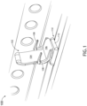
- FIG. 1 illustrates an aircraft cabin 100 including an aircraft seat 102, in accordance with one or more embodiments of the disclosure.
- the aircraft seat 102 may include a seat back 104.
- the aircraft seat 102 may include a seat pan 106.
- the aircraft seat 102 may include one or more arms 108.
- the aircraft seat 102 may be coupled to a base 110.
- the base 110 may be covered by a shroud 112.
- the shroud 112 may include one or more sections configured to cover at least a portion of the aircraft seat 102.
- the shroud 112 may include a bucket shroud section and a base shroud section. It is noted herein, however, that the shroud 112 may be formed from one piece (e.g., includes a single section).
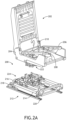
- the aircraft seat 102 may include a vertical adjustment system 200. It is noted that the vertical adjustment system 200 may be adapted and mounted in any orientation to cater to various aircraft seat base designs and requirements. For example, as shown in FIGS. 2A-2B , the vertical adjustment system 200 may be mounted in an upright orientation of the aircraft seat 102. By way of another example, as shown in FIGS. 3A-3C , the vertical adjustment system 200 may be mounted in an upside down orientation of the aircraft seat 102.
- the aircraft seat 102 may include a seat back frame 202.
- the aircraft seat 102 may include a seat frame 204.
- the aircraft seat 102 may include a seat pan frame 206.
- the seat frame 204 may include one or more components 208 and/or one or more components 210.
- the one or more components 208, 210 may be configured to allow and/or assist the aircraft seat 102 to recline and/or return to an upright position.
- One or more of the seat back frame 202 and/or the seat pan frame 206 may be directly coupled, or indirectly coupled via one or more interconnecting components, to the one or more of the components 208, 210 of the seat frame 204.
- At least a portion of the shroud 112 e.g., the bucket shroud section of the shroud 112 may be configured to cover the seat frame 204 and/or the seat pan 206.
- the aircraft seat 102 may include a base assembly 212.
- the base assembly 212 may include one or more base rails 214 (e.g., tubes, bars, or the like).
- the one or more base rails 214 may be positioned relative to a particular direction of travel of the aircraft seat 102 including, but not limited to, perpendicular (e.g., cross-wise), parallel (e.g., cross-wise), or the like.
- the one or more base rails 214 may be positioned relative to a same or a different direction of travel of the aircraft seat 102.
- the base assembly 212 may include one or more base brackets 216.
- the one or more base rails 214 may be coupled together via the one or more base brackets 216.
- a base bracket 216 may couple together an adjacent base rail 214 and base rail 214 at any angle, such that the base assembly 212 may include an outline of any geometric shape known in the art.
- the outline may be rectangular or substantially rectangular. Therefore, the above description should not be interpreted as a limitation on the present disclosure but merely an illustration.
- the one or more base brackets 216 may be coupled to a set of floor tracks 218 of the aircraft cabin 100 (e.g., as illustrated in FIG. 1 ) via one or more floor fittings 220. At least a portion of the shroud 112 (e.g., the base shroud section of the shroud 112) may be configured to cover the base assembly 212.
- the aircraft seat 102 may include a base assembly 312.
- the base assembly 312 may include one or more fixed base rails 302.
- the one or more fixed base rails 302 may be coupled to a set of floor tracks of the aircraft cabin 100 (e.g., as illustrated in FIG. 1 ) via one or more floor fittings 304.
- At least a portion of the shroud 112 (e.g., the base shroud section of the shroud 112) may be configured to cover the base assembly.
- the seat 102 and the base 110 may be coupled together via the vertical adjustment system 200.
- the seat frame 204 of the seat 102 e.g., as illustrated in FIG. 1
- the base assembly 212, 312 of the base 110 e.g., as illustrated in FIG. 1
- the vertical adjustment system 200 may include a swivel assembly 222 attached to the aircraft seat 102 and a tracking assembly 224 attached to the base 110, wherein the swivel assembly and tracking assembly may be attached via an actuation assembly.
- the vertical adjustment system 200 may include a swivel assembly 222 attached to the base and a tracking assembly 224 attached to the aircraft seat 102, wherein the swivel assembly and tracking assembly may be attached via an actuation assembly.
- the vertical adjustment system 200 includes a swivel assembly 222 configured to rotate (e.g., swivel) the aircraft seat 102 relative to the tracking assembly about an axis through the vertical adjustment system.
- a swivel assembly 222 configured to rotate (e.g., swivel) the aircraft seat 102 relative to the tracking assembly about an axis through the vertical adjustment system.
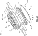
- the swivel assembly 222 includes a swivel mechanism 500 and a traversely-extending spar 502.
- the swivel mechanism is preferably integrally-formed with and forms the spar (e.g., a "sparvel" mechanism).
- the swivel mechanism includes a swivel plate 504 (e.g., an outer ring).
- the swivel plate includes integrally-formed connecting members 506.
- the integrally-formed connecting members is configured to mount to a portion of the aircraft seat 102.
- the integrally-formed connecting members 506 may be configured to mount to the seat frame 204 of the aircraft seat 102.
- the integrally-formed connecting members 506 may include one or more bolt holes positioned to align with one or more bolts holes of the seat frame.
- the swivel assembly thus becomes the spar, mounting the seat frame and the attached seat back to the base rails without adding height to the seat.
- the integrally-formed connecting members may be configured to mount to the one or more fixed base rails 302 of the base assembly 312.
- the integrally-formed connecting members may include one or more bolt holes positioned to align with one or more bolt holes of the one or more fixed base rails 302.
- the swivel assembly thus becomes the spar, mounting the base rails to the seat frame and the attached seat back without adding height to the seat.
- the swivel mechanism may include one or more inner rings.
- the swivel mechanism may include a first inner ring 512.
- the swivel mechanism may include an additional inner ring 516.
- the outer ring 504 (swivel plate 504) may be positioned between the first inner ring 512 and the additional inner ring 516.
- the one or more inner rings 512, 516 may be configured to rotate.
- the outer ring 504 may be configured to rotate.
- the swivel mechanism may include one or more ball bearings 514.
- the swivel mechanism may include a first ball bearing 514 positioned between the outer 504 (swivel plate 504) and the first inner ring 512.
- the swivel mechanism may include an additional ball bearing 514 positioned between the outer 504 (swivel plate 504) and the additional inner ring 516.
- the swivel mechanism may include a toothed ring 518 configured to arrest the relative motion between the inner rings and the outer ring as required in the upright or upside down configuration.
- the swivel mechanism may include one or more fasteners 520 configured to couple the one or more swivel mechanism components to each other.
- the first inner ring 512 may include one or more fastener holes configured to receive a portion of the one or more fasteners 520.
- the vertical adjustment system includes a tracking assembly 224 configured to allow the aircraft seat 102 to move side-to-side and fore-and-aft within a select range of motion.
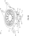
- the swivel assembly 222 includes a plurality of pillow block assemblies 511.
- the swivel plate may be configured to couple to four or more pillow block assemblies 511.
- each pillow block assembly 511 may be configured to couple to the outer ring 504.
- Each pillow block assembly 511 includes a pillow block 508 and a plurality of rollers 510.
- each pillow block assembly 511 may include a pillow block 508 and four or more rollers 510.
- the plurality of rollers 510 may be configured to provide stable vertical movement along the vertical stabilizer rods 606 of the tracking assembly 224.
- the tracking assembly 224 includes a plurality of slide tubes 600.
- the tracking assembly 224 may include one or more slide tubes 600 for side-to-side translating movement.
- the tracking assembly 224 may include one or more slide tubes 600 for fore-and-aft translating movement.
- the seat frame and the attached seat back may be permitted to slide side-to-side and fore-and-aft within the range of motion providing by the length of the slide tubes.
- the plurality of slide tubes 600 may be locked via a tube locking mechanism 608.
- the locking mechanism 608 may be configured to engage the plurality of slide tubes 600 to cause the plurality of slide tubes 600 to lock in a select position. This permits a seated passenger a wide range of seat adjustment during travel, as well as the ability to slide the aircraft seat 102 away from the fuselage and aft while swiveling via the swiveling assembly to comfortably stand up and leave the aircraft seat.
- the tracking assembly includes a plurality of slide bearings 602 configured to receive a portion of the plurality of slide tubes 600.
- the tracking assembly 224 may include one or more slide bearings 602 for side-to-side translating movement.
- the one or more slide bearings 602 for side-to-side translating may be configured to receive one or more slide tubes 600 for side-to-side translating.
- the slide tube may slide/translate a select distance based on the length of the slide tube.
- the tracking assembly 224 may include one or more slide bearings 602 for fore-and-aft translating movement.
- the one or more slide bearings 602 for fore-and-aft translating movement may be configured to receive one or more slide tubes 600 for fore-and-aft translating movement.
- the slide tube may slide/translate a select distance based on the length of the slide tube.
- the tracking assembly 224 includes a tracking plate 604.
- the tracking plate 604 may include a plurality stabilizer rods 606.
- the plurality stabilizer rods 606 may be configured to couple to the swivel assembly 222 via the pillow block assemblies 511.
- the swivel assembly 222 including the pillow block assemblies 511 may be configured to couple to the tracking assembly 224 via the four or more vertical stabilizer rods 606.
- the pillow block assemblies 511 may be configured to provide stable vertical movement via the plurality of vertical stabilizer rods 606 and the plurality of rollers 510.
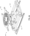
- the tracking assembly 224 may couple to the swivel assembly 222 via the one or more stabilizer rods 606 and plurality of vertical rollers 510 It is noted that the tracking assembly 224 and the swivel assembly 222 may be adapted and mounted in any orientation to cater to various aircraft seat base designs and requirements. For example, as shown in FIG. 4A , the tracking assembly 224 and the swivel assembly 222 may be mounted in an upright orientation of the aircraft seat 102. For instance, the swivel assembly 222 may be mounted to the seat frame and the tracking assembly 224 may be mounted to the base assembly. By way of another example, as shown in FIG.
- the tracking assembly 224 and the swivel assembly 222 may be mounted in an upside down orientation of the aircraft seat 102.
- the swivel assembly 222 may be mounted to the base assembly and the tracking assembly 224 may be mounted to the seat frame.
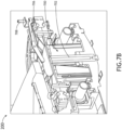
- the vertical adjustment system 200 includes an actuation assembly 700 configured to adjust a vertical height of the aircraft seat 102.
- the actuation assembly 700 may be configured to provide at least approximately 3 inches of vertical adjustment, with infinite positions between the lowest and highest positions.
- the actuation assembly 700 may be configured to allow the aircraft seat 102 to raise vertically between 0-7.62cm (0-3 inches), with infinite positions between 0-7.62cm (0-3 inches).
- the actuation assembly 700 includes an actuator 702 configured to adjust a vertical height of the aircraft seat 102.
- the actuation assembly 700 may include any type of actuator including, but not limited to, a gas spring actuator, hydraulic actuator, coil spring-damper actuation system, a rotary actuator, or the like.
- the actuation assembly 700 includes a release mechanism 704 configured to couple to a rotary portion of the sparvel.
- the release mechanism 704 will rotate along with the seat's swivel, thus there is no need to have slack.
- the release mechanism 704 may include a pull lever 706 and a conduit 708 to release the actuator 702.
- the conduit 708 may be pulled up to pivot the pull lever 706 down to release the actuator 702.
- the release mechanism 704 may include one or more brackets 710 configured to hold one or more components of the release mechanism.
- the release mechanism may include a bracket 710 configured to hold the pull lever 706.
- the bracket 710 may couple to one or more portions of the swivel mechanism to secure the pull lever 706.
- the release mechanism 704 may include a bracket 710 configured to hold the cable conduit 708.
- the bracket 710 may couple to one or more portions of the swivel mechanism to secure the cable conduit 708.
- the aircraft seat 102 may be adjusted electrically.
- the aircraft seat 102 may include a control panel for adjusting the aircraft seat 102.
- the control panel may be coupled to an aircraft controller.
- the conduit 708 may directly run into the a control panel coupled to the arms 108 of the aircraft seat 102.
- a passenger may electrically adjust one of swivel, tracking, or vertical height via the control panel.
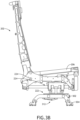
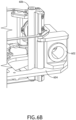
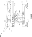
- FIGS. 8A-8B in general illustrate a helix vertical adjustment system 800 for an aircraft seat 102, in accordance with one or more embodiments of the disclosure. It is noted that the description of the various embodiments, components, and operations described previously herein with respect to the aircraft seat 102 should be interpreted to extend to the system 800, and vice versa. Further, is noted that the description of the various embodiments, components, and operations described previously herein with respect to the system 200 should be interpreted to extend to the system 800, and vice versa, unless otherwise noted herein.
- the aircraft seat 102 may include a helix vertical adjustment system 800.
- the vertical adjustment system 200 may be adapted and mounted in any orientation to cater to various aircraft seat base designs and requirements.
- the helix vertical adjustment system 800 may be mounted in an upright orientation of the aircraft seat 102.
- a portion of the helix adjustment system 800 may be hard mounted to a portion of the tracking plate.
- the helix vertical adjustment system 800 may be mounted in an upside down orientation of the aircraft seat 102.
- the helix vertical adjustment system 800 may include a swivel plate 504 including integral-connecting members 506 and a traversely-extending spar (e.g., a sparvel) and the tracking assembly 224.
- a swivel plate 504 including integral-connecting members 506 and a traversely-extending spar (e.g., a sparvel) and the tracking assembly 224.
- the helix vertical adjustment system 800 may include a helix swivel mechanism 802 configured to allow the aircraft seat 102 to rotate (e.g., swivel) about a central axis.
- the helix swivel mechanism 802 may include a shaft 804 including one or more helical protrusions 806 (e.g., protrusions in a helical configuration).
- the shaft 804 may be mounted to a portion of the swivel plate 504. It is noted that the helix swivel mechanism 802 may be configured to provide rigidity for the adjustment system 800.
- the helix vertical adjustment system 800 may include an actuator 808 configured to adjust a vertical height of the aircraft seat 102.
- the adjustment system 800 may include any type of actuator including, but not limited to, a gas spring actuator, hydraulic actuator, coil spring-damper actuation system, a rotary actuator, or the like.
- the actuator 808 may include a gas spring configured to be mounted within the shaft 804 of the helix mechanism 802 to adjust a vertical height of the aircraft seat 102.
- the shaft 804 may include an internal cavity to house the actuator 808.
- the helix vertical adjustment system 800 may include a locking mechanism 810 configured to lock the aircraft seat 102 in a select position.
- the helix vertical adjustment system 800 may include a ring brake locking mechanism 810.
- the helix vertical adjustment system 800 may include one or more stabilizer rods 810.
- the helix vertical adjustment system 800 may include one or more vertical stabilizer rods 606 configured to couple to a portion of the base assembly (e.g., fixed base rails) and a portion of the locking mechanism 808. It is noted that the one or more stabilizer rods 606 may be configured to provide additional rigidity for the adjustment system 800.
- vertical may be understood as being defined with respect to a z-axis as illustrated in the Figures.
- horizontal may be understood as being defined with respect to an x-axis or a y-axis as illustrated in the Figures.
Landscapes
- Engineering & Computer Science (AREA)
- Aviation & Aerospace Engineering (AREA)
- Mechanical Engineering (AREA)
- General Engineering & Computer Science (AREA)
- Transportation (AREA)
- Seats For Vehicles (AREA)
Claims (8)
- Vertikales Verstellsystem (200) für einen Luftfahrzeugsitz, umfassend:
eine Schwenkbaugruppe (222), wobei die Schwenkbaugruppe (222) Folgendes umfasst:eine Schwenkplatte (504), die einstückig ausgebildete Verbindungselemente (506) beinhaltet,wobei die einstückig ausgebildeten Verbindungselemente dazu konfiguriert sind, mit einem Abschnitt des Luftfahrzeugsitzes gekoppelt zu sein; undeinen Schwenkmechanismus (500), der dazu konfiguriert ist, den Luftfahrzeugsitz um eine Mittelachse des Luftfahrzeugsitzes zu drehen;eine Spurbaugruppe (224), wobei die Spurbaugruppe (224) Folgendes umfasst:eine Vielzahl von Gleitrohren (600), die dazu konfiguriert ist, den Luftfahrzeugsitz eines von Seite zu Seite oder von vorne nach hinten zu verschieben;eine Vielzahl von Gleitlagern (602), die dazu konfiguriert sind, einen Abschnitt der Vielzahl von Gleitrohren aufzunehmen; undeine Spurplatte (604), die mit der Vielzahl von Gleitlagern (602) gekoppelt ist; undeine Betätigungsbaugruppe (700), wobei die Betätigungsbaugruppe Folgendes umfasst:eine Betätigungsvorrichtung (702), die dazu konfiguriert ist, eine vertikale Höhenverstellung für den Luftfahrzeugsitz bereitzustellen, wobei die Betätigungsvorrichtung dazu konfiguriert ist, eine relative Bewegung zwischen einer Basisbaugruppe (212, 312) des Luftfahrzeugsitzes und einem oberen Abschnitt des Luftfahrzeugsitzes anzuhalten;einen Freigabemechanismus (704), wobei der Freigabemechanismus (704) dazu konfiguriert ist, mit einem Drehabschnitt der Schwenkplatte gekoppelt zu werden, wobei der Freigabemechanismus (704) dazu konfiguriert ist, die Betätigungsvorrichtung freizugeben;eine Vielzahl von vertikalen Stabilisatorstangen (606), die mit einem Abschnitt der Spurplatte gekoppelt ist; undeine Stehlagerbaugruppe (511), wobei die Stehlagerbaugruppe Folgendes umfasst:eine Vielzahl von Stehlagern (508), die mit einem Abschnitt der Schwenkplatte gekoppelt ist; undeine Vielzahl von Rollen (510), die mit einem Abschnitt der Vielzahl von Stehlagern gekoppelt ist, wobei die Vielzahl von Rollen (510) dazu konfiguriert ist, einen Abschnitt der Vielzahl von Stabilisatorstangen aufzunehmen, wobei die Vielzahl von Rollen (510) dazu konfiguriert ist, Stabilität entlang den vertikalen Stabilisatorstangen bereitzustellen, wenn die Betätigungsvorrichtung die vertikale Höheneinstellung bereitstellt. - System nach Anspruch 1, wobei der Schwenkmechanismus (50) Folgendes umfasst:einen ersten Innenring (512);einen zusätzlichen Innenring (516), wobei die Schwenkplatte zwischen dem ersten Innenring (512) und dem zusätzlichen Innenring (516) positioniert ist;ein oder mehrere Kugellager, wobei das eine oder die mehreren Kugellager zwischen der Schwenkplatte (504) und mindestens einem des ersten Innenrings (512) oder des zusätzlichen Innenrings (516) positioniert sind; undeinen Verriegelungsring, wobei der Verriegelungsring einen oder mehrere Zähne beinhaltet, um die relative Bewegung zwischen der Schwenkplatte und mindestens einem des ersten Innenrings (512) oder des zusätzlichen Innenrings (516) anzuhalten.
- System nach Anspruch 1 oder 2, wobei der Schwenkmechanismus (50) Folgendes umfasst:einen Helix-Schwenkmechanismus (500), wobei der Helix-Schwenkmechanismus eine Welle beinhaltet, wobei die Welle einen oder mehrere helixförmige Vorsprünge beinhaltet; undeinen Verriegelungsmechanismus (810), der dazu konfiguriert ist, den Helix-Schwenkmechanismus in Eingriff zu nehmen, um den Luftfahrzeugsitz in einer ausgewählten Position zu verriegeln.
- System nach einem der vorhergehenden Ansprüche, wobei der Freigabemechanismus Folgendes umfasst:einen Zughebel (706), der mit einem Abschnitt der Schwenkplatte gekoppelt ist; undein oder mehrere Zugkabel, die mit einem Abschnitt des Zughebels gekoppelt sind, wobei das eine oder die mehreren Zugkabel dazu konfiguriert sind, den Zughebel zu ziehen, um die Betätigungsvorrichtung freizugeben.
- System nach einem der vorhergehenden Ansprüche, wobei die einstückig ausgebildeten Verbindungselemente dazu konfiguriert sind, mit einem Abschnitt eines Sitzrahmens des Luftfahrzeugsitzes gekoppelt zu werden.
- System nach Anspruch 5, wobei die Spurbaugruppe (224) dazu konfiguriert ist, mit einem Abschnitt der Basisbaugruppe (212, 312) des Luftfahrzeugsitzes gekoppelt zu werden.
- System nach einem der Ansprüche 1-4, wobei die einstückig ausgebildeten Verbindungselemente dazu konfiguriert sind, mit einem Abschnitt der Basisbaugruppe (212, 312) des Luftfahrzeugsitzes gekoppelt zu werden.
- System nach Anspruch 7, wobei die Spurbaugruppe (224) dazu konfiguriert ist, mit einem Abschnitt eines Sitzrahmens des Luftfahrzeugsitzes gekoppelt zu werden.
Applications Claiming Priority (2)
| Application Number | Priority Date | Filing Date | Title |
|---|---|---|---|
| IN202141018639 | 2021-04-22 | ||
| US17/338,037 US11613361B2 (en) | 2021-04-22 | 2021-06-03 | Vertical adjustment system for an aircraft seat |
Publications (2)
| Publication Number | Publication Date |
|---|---|
| EP4079636A1 EP4079636A1 (de) | 2022-10-26 |
| EP4079636B1 true EP4079636B1 (de) | 2024-11-13 |
Family
ID=81327994
Family Applications (1)
| Application Number | Title | Priority Date | Filing Date |
|---|---|---|---|
| EP22167211.6A Active EP4079636B1 (de) | 2021-04-22 | 2022-04-07 | Höhenverstellmechanismus für einen flugzeugsitz |
Country Status (1)
| Country | Link |
|---|---|
| EP (1) | EP4079636B1 (de) |
Families Citing this family (3)
| Publication number | Priority date | Publication date | Assignee | Title |
|---|---|---|---|---|
| US11613361B2 (en) * | 2021-04-22 | 2023-03-28 | B/E Aerospace, Inc. | Vertical adjustment system for an aircraft seat |
| US12391387B2 (en) * | 2023-04-26 | 2025-08-19 | Embraer S.A. | Aircraft seat system |
| US12534208B2 (en) * | 2023-08-02 | 2026-01-27 | Textron Innovations Inc. | Swivel indicating mechanism for aircraft seat |
Citations (1)
| Publication number | Priority date | Publication date | Assignee | Title |
|---|---|---|---|---|
| US20060290186A1 (en) * | 2005-06-24 | 2006-12-28 | Honda Motor Co., Ltd. | Seat apparatus for vehicles |
Family Cites Families (4)
| Publication number | Priority date | Publication date | Assignee | Title |
|---|---|---|---|---|
| US7108325B2 (en) * | 2004-10-08 | 2006-09-19 | B/E Aerospace, Inc. | Movable seat with tapered swivel assembly and cable track wheel |
| US20090127908A1 (en) * | 2007-10-04 | 2009-05-21 | John Kucharski | Seat Swivel Mechanism |
| US9242581B2 (en) * | 2014-06-25 | 2016-01-26 | Ford Global Technologies, Llc | Automatic presentable swiveling seat |
| CN112298574A (zh) * | 2020-10-29 | 2021-02-02 | 隋乾辉 | 一种飞机座椅垂直减震调节系统 |
-
2022
- 2022-04-07 EP EP22167211.6A patent/EP4079636B1/de active Active
Patent Citations (1)
| Publication number | Priority date | Publication date | Assignee | Title |
|---|---|---|---|---|
| US20060290186A1 (en) * | 2005-06-24 | 2006-12-28 | Honda Motor Co., Ltd. | Seat apparatus for vehicles |
Also Published As
| Publication number | Publication date |
|---|---|
| EP4079636A1 (de) | 2022-10-26 |
Similar Documents
| Publication | Publication Date | Title |
|---|---|---|
| US11613361B2 (en) | Vertical adjustment system for an aircraft seat | |
| EP4079636B1 (de) | Höhenverstellmechanismus für einen flugzeugsitz | |
| US11542014B2 (en) | Gravity-assisted tracking base assembly for aircraft seat | |
| EP2794396B1 (de) | Passagiersitz und sitzdrehplatte | |
| EP4101765B1 (de) | Flugzeugsitz | |
| US9421886B2 (en) | Bucket seat with changing kinematics | |
| EP4194261B1 (de) | Flugzeugsitzbasisanordnung | |
| EP4257490A1 (de) | Sitzanordnungen und verfahren zur änderung des sitzwinkels gemäss der flugzeugflugart | |
| EP3517435B1 (de) | Verstellbare schwenkbare passagiersitzanordnung | |
| US11814178B2 (en) | Lift assist system for an aircraft seat | |
| EP4600152A1 (de) | Flugzeugsitzbasisverfolgungssystem | |
| US12595061B2 (en) | Modular power box mounting system | |
| US20250353598A1 (en) | Modular power box mounting system | |
| US20250256850A1 (en) | Aircraft seat base tracking system | |
| EP4144645A1 (de) | Hubunterstützungssystem in einem flugzeugsitz | |
| EP4442505A1 (de) | Modulare rückenlehnenstruktur für flugzeugsitze | |
| US12515801B2 (en) | Modular backrest structure for aircraft seats | |
| EP4015385B1 (de) | Flugzeugpassagiersitzreihe mit flugbegleitersitz | |
| US12522361B2 (en) | Recline lockout device for aircraft seat | |
| US11572001B1 (en) | Quick release headrest removal assembly | |
| EP4311773A1 (de) | Bewegungssteuerungssystem für einen flugzeugsitz | |
| US20240025549A1 (en) | Tracking system for an aircraft seat |
Legal Events
| Date | Code | Title | Description |
|---|---|---|---|
| PUAI | Public reference made under article 153(3) epc to a published international application that has entered the european phase |
Free format text: ORIGINAL CODE: 0009012 |
|
| STAA | Information on the status of an ep patent application or granted ep patent |
Free format text: STATUS: THE APPLICATION HAS BEEN PUBLISHED |
|
| AK | Designated contracting states |
Kind code of ref document: A1 Designated state(s): AL AT BE BG CH CY CZ DE DK EE ES FI FR GB GR HR HU IE IS IT LI LT LU LV MC MK MT NL NO PL PT RO RS SE SI SK SM TR |
|
| STAA | Information on the status of an ep patent application or granted ep patent |
Free format text: STATUS: REQUEST FOR EXAMINATION WAS MADE |
|
| 17P | Request for examination filed |
Effective date: 20230426 |
|
| RBV | Designated contracting states (corrected) |
Designated state(s): AL AT BE BG CH CY CZ DE DK EE ES FI FR GB GR HR HU IE IS IT LI LT LU LV MC MK MT NL NO PL PT RO RS SE SI SK SM TR |
|
| P01 | Opt-out of the competence of the unified patent court (upc) registered |
Effective date: 20230922 |
|
| GRAP | Despatch of communication of intention to grant a patent |
Free format text: ORIGINAL CODE: EPIDOSNIGR1 |
|
| STAA | Information on the status of an ep patent application or granted ep patent |
Free format text: STATUS: GRANT OF PATENT IS INTENDED |
|
| INTG | Intention to grant announced |
Effective date: 20240701 |
|
| GRAS | Grant fee paid |
Free format text: ORIGINAL CODE: EPIDOSNIGR3 |
|
| GRAA | (expected) grant |
Free format text: ORIGINAL CODE: 0009210 |
|
| STAA | Information on the status of an ep patent application or granted ep patent |
Free format text: STATUS: THE PATENT HAS BEEN GRANTED |
|
| AK | Designated contracting states |
Kind code of ref document: B1 Designated state(s): AL AT BE BG CH CY CZ DE DK EE ES FI FR GB GR HR HU IE IS IT LI LT LU LV MC MK MT NL NO PL PT RO RS SE SI SK SM TR |
|
| REG | Reference to a national code |
Ref country code: GB Ref legal event code: FG4D |
|
| REG | Reference to a national code |
Ref country code: CH Ref legal event code: EP |
|
| REG | Reference to a national code |
Ref country code: DE Ref legal event code: R096 Ref document number: 602022007612 Country of ref document: DE |
|
| REG | Reference to a national code |
Ref country code: IE Ref legal event code: FG4D |
|
| REG | Reference to a national code |
Ref country code: LT Ref legal event code: MG9D |
|
| REG | Reference to a national code |
Ref country code: NL Ref legal event code: MP Effective date: 20241113 |
|
| PG25 | Lapsed in a contracting state [announced via postgrant information from national office to epo] |
Ref country code: HR Free format text: LAPSE BECAUSE OF FAILURE TO SUBMIT A TRANSLATION OF THE DESCRIPTION OR TO PAY THE FEE WITHIN THE PRESCRIBED TIME-LIMIT Effective date: 20241113 Ref country code: IS Free format text: LAPSE BECAUSE OF FAILURE TO SUBMIT A TRANSLATION OF THE DESCRIPTION OR TO PAY THE FEE WITHIN THE PRESCRIBED TIME-LIMIT Effective date: 20250313 Ref country code: PT Free format text: LAPSE BECAUSE OF FAILURE TO SUBMIT A TRANSLATION OF THE DESCRIPTION OR TO PAY THE FEE WITHIN THE PRESCRIBED TIME-LIMIT Effective date: 20250313 |
|
| PG25 | Lapsed in a contracting state [announced via postgrant information from national office to epo] |
Ref country code: FI Free format text: LAPSE BECAUSE OF FAILURE TO SUBMIT A TRANSLATION OF THE DESCRIPTION OR TO PAY THE FEE WITHIN THE PRESCRIBED TIME-LIMIT Effective date: 20241113 Ref country code: NL Free format text: LAPSE BECAUSE OF FAILURE TO SUBMIT A TRANSLATION OF THE DESCRIPTION OR TO PAY THE FEE WITHIN THE PRESCRIBED TIME-LIMIT Effective date: 20241113 |
|
| REG | Reference to a national code |
Ref country code: AT Ref legal event code: MK05 Ref document number: 1741511 Country of ref document: AT Kind code of ref document: T Effective date: 20241113 |
|
| PG25 | Lapsed in a contracting state [announced via postgrant information from national office to epo] |
Ref country code: BG Free format text: LAPSE BECAUSE OF FAILURE TO SUBMIT A TRANSLATION OF THE DESCRIPTION OR TO PAY THE FEE WITHIN THE PRESCRIBED TIME-LIMIT Effective date: 20241113 |
|
| PG25 | Lapsed in a contracting state [announced via postgrant information from national office to epo] |
Ref country code: ES Free format text: LAPSE BECAUSE OF FAILURE TO SUBMIT A TRANSLATION OF THE DESCRIPTION OR TO PAY THE FEE WITHIN THE PRESCRIBED TIME-LIMIT Effective date: 20241113 |
|
| PG25 | Lapsed in a contracting state [announced via postgrant information from national office to epo] |
Ref country code: NO Free format text: LAPSE BECAUSE OF FAILURE TO SUBMIT A TRANSLATION OF THE DESCRIPTION OR TO PAY THE FEE WITHIN THE PRESCRIBED TIME-LIMIT Effective date: 20250213 |
|
| PG25 | Lapsed in a contracting state [announced via postgrant information from national office to epo] |
Ref country code: GR Free format text: LAPSE BECAUSE OF FAILURE TO SUBMIT A TRANSLATION OF THE DESCRIPTION OR TO PAY THE FEE WITHIN THE PRESCRIBED TIME-LIMIT Effective date: 20250214 Ref country code: AT Free format text: LAPSE BECAUSE OF FAILURE TO SUBMIT A TRANSLATION OF THE DESCRIPTION OR TO PAY THE FEE WITHIN THE PRESCRIBED TIME-LIMIT Effective date: 20241113 Ref country code: LV Free format text: LAPSE BECAUSE OF FAILURE TO SUBMIT A TRANSLATION OF THE DESCRIPTION OR TO PAY THE FEE WITHIN THE PRESCRIBED TIME-LIMIT Effective date: 20241113 |
|
| PG25 | Lapsed in a contracting state [announced via postgrant information from national office to epo] |
Ref country code: PL Free format text: LAPSE BECAUSE OF FAILURE TO SUBMIT A TRANSLATION OF THE DESCRIPTION OR TO PAY THE FEE WITHIN THE PRESCRIBED TIME-LIMIT Effective date: 20241113 |
|
| PGFP | Annual fee paid to national office [announced via postgrant information from national office to epo] |
Ref country code: FR Payment date: 20250319 Year of fee payment: 4 |
|
| PG25 | Lapsed in a contracting state [announced via postgrant information from national office to epo] |
Ref country code: RS Free format text: LAPSE BECAUSE OF FAILURE TO SUBMIT A TRANSLATION OF THE DESCRIPTION OR TO PAY THE FEE WITHIN THE PRESCRIBED TIME-LIMIT Effective date: 20250213 |
|
| PG25 | Lapsed in a contracting state [announced via postgrant information from national office to epo] |
Ref country code: SM Free format text: LAPSE BECAUSE OF FAILURE TO SUBMIT A TRANSLATION OF THE DESCRIPTION OR TO PAY THE FEE WITHIN THE PRESCRIBED TIME-LIMIT Effective date: 20241113 |
|
| PGFP | Annual fee paid to national office [announced via postgrant information from national office to epo] |
Ref country code: DE Payment date: 20250319 Year of fee payment: 4 |
|
| PG25 | Lapsed in a contracting state [announced via postgrant information from national office to epo] |
Ref country code: DK Free format text: LAPSE BECAUSE OF FAILURE TO SUBMIT A TRANSLATION OF THE DESCRIPTION OR TO PAY THE FEE WITHIN THE PRESCRIBED TIME-LIMIT Effective date: 20241113 |
|
| PG25 | Lapsed in a contracting state [announced via postgrant information from national office to epo] |
Ref country code: EE Free format text: LAPSE BECAUSE OF FAILURE TO SUBMIT A TRANSLATION OF THE DESCRIPTION OR TO PAY THE FEE WITHIN THE PRESCRIBED TIME-LIMIT Effective date: 20241113 |
|
| PG25 | Lapsed in a contracting state [announced via postgrant information from national office to epo] |
Ref country code: RO Free format text: LAPSE BECAUSE OF FAILURE TO SUBMIT A TRANSLATION OF THE DESCRIPTION OR TO PAY THE FEE WITHIN THE PRESCRIBED TIME-LIMIT Effective date: 20241113 |
|
| PG25 | Lapsed in a contracting state [announced via postgrant information from national office to epo] |
Ref country code: SK Free format text: LAPSE BECAUSE OF FAILURE TO SUBMIT A TRANSLATION OF THE DESCRIPTION OR TO PAY THE FEE WITHIN THE PRESCRIBED TIME-LIMIT Effective date: 20241113 |
|
| PG25 | Lapsed in a contracting state [announced via postgrant information from national office to epo] |
Ref country code: CZ Free format text: LAPSE BECAUSE OF FAILURE TO SUBMIT A TRANSLATION OF THE DESCRIPTION OR TO PAY THE FEE WITHIN THE PRESCRIBED TIME-LIMIT Effective date: 20241113 |
|
| PG25 | Lapsed in a contracting state [announced via postgrant information from national office to epo] |
Ref country code: IT Free format text: LAPSE BECAUSE OF FAILURE TO SUBMIT A TRANSLATION OF THE DESCRIPTION OR TO PAY THE FEE WITHIN THE PRESCRIBED TIME-LIMIT Effective date: 20241113 |
|
| REG | Reference to a national code |
Ref country code: DE Ref legal event code: R097 Ref document number: 602022007612 Country of ref document: DE |
|
| PG25 | Lapsed in a contracting state [announced via postgrant information from national office to epo] |
Ref country code: SE Free format text: LAPSE BECAUSE OF FAILURE TO SUBMIT A TRANSLATION OF THE DESCRIPTION OR TO PAY THE FEE WITHIN THE PRESCRIBED TIME-LIMIT Effective date: 20241113 |
|
| PLBE | No opposition filed within time limit |
Free format text: ORIGINAL CODE: 0009261 |
|
| STAA | Information on the status of an ep patent application or granted ep patent |
Free format text: STATUS: NO OPPOSITION FILED WITHIN TIME LIMIT |
|
| 26N | No opposition filed |
Effective date: 20250814 |
|
| REG | Reference to a national code |
Ref country code: CH Ref legal event code: H13 Free format text: ST27 STATUS EVENT CODE: U-0-0-H10-H13 (AS PROVIDED BY THE NATIONAL OFFICE) Effective date: 20251125 |
|
| PG25 | Lapsed in a contracting state [announced via postgrant information from national office to epo] |
Ref country code: LU Free format text: LAPSE BECAUSE OF NON-PAYMENT OF DUE FEES Effective date: 20250407 |
|
| PG25 | Lapsed in a contracting state [announced via postgrant information from national office to epo] |
Ref country code: MC Free format text: LAPSE BECAUSE OF FAILURE TO SUBMIT A TRANSLATION OF THE DESCRIPTION OR TO PAY THE FEE WITHIN THE PRESCRIBED TIME-LIMIT Effective date: 20241113 |
|
| REG | Reference to a national code |
Ref country code: BE Ref legal event code: MM Effective date: 20250430 |
|
| PG25 | Lapsed in a contracting state [announced via postgrant information from national office to epo] |
Ref country code: BE Free format text: LAPSE BECAUSE OF NON-PAYMENT OF DUE FEES Effective date: 20250430 |
|
| PG25 | Lapsed in a contracting state [announced via postgrant information from national office to epo] |
Ref country code: CH Free format text: LAPSE BECAUSE OF NON-PAYMENT OF DUE FEES Effective date: 20250430 |