EP4144585A2 - Can-bus-adapter für kühlsystem - Google Patents
Can-bus-adapter für kühlsystem Download PDFInfo
- Publication number
- EP4144585A2 EP4144585A2 EP22194397.0A EP22194397A EP4144585A2 EP 4144585 A2 EP4144585 A2 EP 4144585A2 EP 22194397 A EP22194397 A EP 22194397A EP 4144585 A2 EP4144585 A2 EP 4144585A2
- Authority
- EP
- European Patent Office
- Prior art keywords
- connector
- transport refrigeration
- refrigeration system
- port
- adapter
- Prior art date
- Legal status (The legal status is an assumption and is not a legal conclusion. Google has not performed a legal analysis and makes no representation as to the accuracy of the status listed.)
- Granted
Links
Images


Classifications
-
- H—ELECTRICITY
- H01—ELECTRIC ELEMENTS
- H01R—ELECTRICALLY-CONDUCTIVE CONNECTIONS; STRUCTURAL ASSOCIATIONS OF A PLURALITY OF MUTUALLY-INSULATED ELECTRICAL CONNECTING ELEMENTS; COUPLING DEVICES; CURRENT COLLECTORS
- H01R31/00—Coupling parts supported only by co-operation with counterpart
- H01R31/06—Intermediate parts for linking two coupling parts, e.g. adapter
-
- G—PHYSICS
- G05—CONTROLLING; REGULATING
- G05B—CONTROL OR REGULATING SYSTEMS IN GENERAL; FUNCTIONAL ELEMENTS OF SUCH SYSTEMS; MONITORING OR TESTING ARRANGEMENTS FOR SUCH SYSTEMS OR ELEMENTS
- G05B19/00—Program-control systems
- G05B19/02—Program-control systems electric
- G05B19/04—Program control other than numerical control, i.e. in sequence controllers or logic controllers
- G05B19/042—Program control other than numerical control, i.e. in sequence controllers or logic controllers using digital processors
-
- B—PERFORMING OPERATIONS; TRANSPORTING
- B60—VEHICLES IN GENERAL
- B60H—ARRANGEMENTS OF HEATING, COOLING, VENTILATING OR OTHER AIR-TREATING DEVICES SPECIALLY ADAPTED FOR PASSENGER OR GOODS SPACES OF VEHICLES
- B60H1/00—Heating, cooling or ventilating devices
- B60H1/00357—Air-conditioning arrangements specially adapted for particular vehicles
- B60H1/00364—Air-conditioning arrangements specially adapted for particular vehicles for caravans or trailers
-
- B—PERFORMING OPERATIONS; TRANSPORTING
- B60—VEHICLES IN GENERAL
- B60H—ARRANGEMENTS OF HEATING, COOLING, VENTILATING OR OTHER AIR-TREATING DEVICES SPECIALLY ADAPTED FOR PASSENGER OR GOODS SPACES OF VEHICLES
- B60H1/00—Heating, cooling or ventilating devices
- B60H1/00507—Details, e.g. mounting arrangements, desaeration devices
- B60H1/00585—Means for monitoring, testing or servicing the air-conditioning
-
- B—PERFORMING OPERATIONS; TRANSPORTING
- B60—VEHICLES IN GENERAL
- B60H—ARRANGEMENTS OF HEATING, COOLING, VENTILATING OR OTHER AIR-TREATING DEVICES SPECIALLY ADAPTED FOR PASSENGER OR GOODS SPACES OF VEHICLES
- B60H1/00—Heating, cooling or ventilating devices
- B60H1/00642—Control systems or circuits; Control members or indication devices for heating, cooling or ventilating devices
-
- B—PERFORMING OPERATIONS; TRANSPORTING
- B60—VEHICLES IN GENERAL
- B60H—ARRANGEMENTS OF HEATING, COOLING, VENTILATING OR OTHER AIR-TREATING DEVICES SPECIALLY ADAPTED FOR PASSENGER OR GOODS SPACES OF VEHICLES
- B60H1/00—Heating, cooling or ventilating devices
- B60H1/32—Cooling devices
- B60H1/3204—Cooling devices using compression
- B60H1/3232—Cooling devices using compression particularly adapted for load transporting vehicles
-
- F—MECHANICAL ENGINEERING; LIGHTING; HEATING; WEAPONS; BLASTING
- F25—REFRIGERATION OR COOLING; COMBINED HEATING AND REFRIGERATION SYSTEMS; HEAT PUMP SYSTEMS; MANUFACTURE OR STORAGE OF ICE; LIQUEFACTION SOLIDIFICATION OF GASES
- F25D—REFRIGERATORS; COLD ROOMS; ICE-BOXES; COOLING OR FREEZING APPARATUS NOT OTHERWISE PROVIDED FOR
- F25D11/00—Self-contained movable devices, e.g. domestic refrigerators
- F25D11/003—Transport containers
-
- F—MECHANICAL ENGINEERING; LIGHTING; HEATING; WEAPONS; BLASTING
- F25—REFRIGERATION OR COOLING; COMBINED HEATING AND REFRIGERATION SYSTEMS; HEAT PUMP SYSTEMS; MANUFACTURE OR STORAGE OF ICE; LIQUEFACTION SOLIDIFICATION OF GASES
- F25D—REFRIGERATORS; COLD ROOMS; ICE-BOXES; COOLING OR FREEZING APPARATUS NOT OTHERWISE PROVIDED FOR
- F25D29/00—Arrangement or mounting of control or safety devices
- F25D29/005—Mounting of control devices
-
- B—PERFORMING OPERATIONS; TRANSPORTING
- B60—VEHICLES IN GENERAL
- B60H—ARRANGEMENTS OF HEATING, COOLING, VENTILATING OR OTHER AIR-TREATING DEVICES SPECIALLY ADAPTED FOR PASSENGER OR GOODS SPACES OF VEHICLES
- B60H1/00—Heating, cooling or ventilating devices
- B60H1/00007—Combined heating, ventilating, or cooling devices
- B60H1/00014—Combined heating, ventilating, or cooling devices for load cargos on load transporting vehicles
-
- G—PHYSICS
- G05—CONTROLLING; REGULATING
- G05B—CONTROL OR REGULATING SYSTEMS IN GENERAL; FUNCTIONAL ELEMENTS OF SUCH SYSTEMS; MONITORING OR TESTING ARRANGEMENTS FOR SUCH SYSTEMS OR ELEMENTS
- G05B2219/00—Program-control systems
- G05B2219/20—Pc systems
- G05B2219/26—Pc applications
- G05B2219/2654—Fridge, refrigerator
-
- H—ELECTRICITY
- H04—ELECTRIC COMMUNICATION TECHNIQUE
- H04L—TRANSMISSION OF DIGITAL INFORMATION, e.g. TELEGRAPHIC COMMUNICATION
- H04L67/00—Network arrangements or protocols for supporting network services or applications
- H04L67/01—Protocols
- H04L67/12—Protocols specially adapted for proprietary or special-purpose networking environments, e.g. medical networks, sensor networks, networks in vehicles or remote metering networks
Definitions
- the invention relates to an adapter for connecting a portable device to a control system of a transport refrigeration system, and a transport refrigeration system comprising an adapter.
- exemplary embodiments of the present disclosure relate to transport refrigeration systems and more particularly to a cable for accessing real time information from a control system of the transport refrigeration system.
- the transport refrigeration system typically includes a compressor, a condenser, an expansion device and an evaporator serially connected by refrigerant lines in a closed refrigerant circuit.
- the compressor of the transport refrigeration system is typically driven by the engine shaft either through a belt drive or by mechanical shaft-to-shaft link (although on-board generators may be used in certain instances).
- the temperature within the container must be maintained within strict temperature limits associated with the particular items being transported, regardless of potentially severe operating conditions imposed by the local environment in which the system is operating.
- pico scopes or recorders are used to collect data and troubleshoot operation of a transport refrigeration system.
- use of such devices and the corresponding evaluation of the collected data is time consuming.
- the controller area network bus of a transport refrigeration system is accessible via a break out box, such a break out box is not directly connectable to the network. Further, the information that may be collected in such a manner is limited.
- an adapter for connecting a portable device to a control system of a transport refrigeration system including a cable having a first end and a second end.
- a first connector is arranged at the first end of the cable and a second connector is arranged at the second end of the cable.
- the first connector is connectable to the portable device and the second connector is receivable within a port of the control system.
- the port of the control system is an engine emission system port.
- the first connector is a nine pin serial male or a nine pin serial female.
- the second connector when the second connector is coupled to the port of the control system, the second connector is operably coupled to an interface bus of the control system.
- the interface bus is a controller area network bus.
- a transport refrigeration system including a control system operable to monitor and control operation of at least one component of the transport refrigeration system.
- the control system includes an interface bus having at least one port.
- At least one module is connected to the interface bus via the at least one port.
- the at least one module includes a portable device directly connected to the interface bus via an adapter.
- the adapter further comprises a cable having a first end and a second end and a first connector arranged at the first end of the cable and a second connector arranged at the second end of the cable, the first connector being coupled to the portable device.
- the first connector is one of a nine pin serial male and a nine pin serial female.
- the at least one port includes an engine emission system port, the second connector being connectable to the engine emission system port.
- the second connector is interchangeable with an engine emission system plug and an engine emission system cap.
- the interface bus is a controller area network bus.
- the portable device is a controller area network reader.
- the portable device is a piece of equipment capable of running a diagnostic and/or prognostic software.
- the transport refrigeration system comprises an adapter as recited herein with reference to the first aspect of the invention.
- the invention according to the second aspect may therefore comprise any of the features recited herein with reference to the first aspect of the invention.
- the adapter according to the first aspect of the invention may be configured for use in the transport refrigeration system of the second aspect of the invention.
- the first and second aspects of the invention may therefore be compatible.
- a transport refrigeration system comprising an adapter as recited herein with reference to the first aspect of the invention.
- the transport refrigeration system may comprise a control system e.g. as described herein with reference to any aspect of the invention.
- the transport refrigeration system may comprise a portable device e.g. as described herein with reference to any aspect of the invention.
- the transport refrigeration system may comprise a port of the control system e.g. as described herein with reference to any aspect of the invention.
- the transport refrigeration system may comprise an interface bus e.g. as described herein with reference to any aspect of the invention.
- the transport refrigeration system may comprise any of the features of the system as recited herein with reference to the second aspect of the invention.
- the transport refrigeration system 20 is associated with a container or trailer 22 that is towed or otherwise transported by a tractor 24 including an operator's compartment or cab 26.
- the transport refrigeration system 20 is able to heat and cool the cargo area of trailer 22, completely by itself, excluding the fuel tank located at the bottom of the trailer 22.
- the transport refrigeration system 20 is typically mounted at the front wall 28 of the trailer 22.
- the transport refrigeration system 20 is illustrated as being mounted to the trailer 22, it should be appreciated by those of skill in the art that embodiments described herein may be applied to any transport refrigeration system such as, for example shipping containers that are shipped by rail or sea (via a watercraft).
- the transport refrigeration system 20 includes a compressor 32, a heat rejection heat exchanger 34 (i.e., condenser), an expansion device 36, and a heat absorption heat exchanger 38 (i.e., evaporator) fluidly connected in a closed loop refrigerant circuit and arranged in a conventional refrigeration cycle.
- a condenser fan 40 is configured to move a flow of air across an exterior of the condenser heat exchanger 34, and an evaporator fan 42 may be used to drive a flow of fluid across an exterior of the evaporator heat exchanger 38.
- low temperature, low pressure refrigerant vapor is compressed by the compressor 32 to a high pressure, high temperature refrigerant vapor and passed from the discharge outlet of the compressor 32 to circulate through the refrigerant circuit to return to the suction inlet of the compressor 32.
- the high temperature, high pressure refrigerant vapor passes into and through the heat exchange tube coil or tube bank of the condenser heat exchanger 34, wherein the refrigerant vapor condenses to a liquid. Downstream from the heat rejection heat exchanger 34, the refrigerant is provided the expansion device 36 before passing through the evaporator heat exchanger 38.
- the liquid refrigerant In traversing the expansion device 36, which may be an electronic expansion valve (“EXV”) or a mechanical thermostatic expansion valve (“TXV”), the liquid refrigerant is expanded to a lower temperature and lower pressure prior to passing to the evaporator heat exchanger 38.
- EXV electronic expansion valve
- TXV mechanical thermostatic expansion valve
- the refrigerant In flowing through the heat exchange tube coil or tube bank of the evaporator heat exchanger 38, the refrigerant evaporates, and is typically superheated, as it passes in heat exchange relationship return air drawn from the cargo space of the trailer 22 passing through the airside pass of the evaporator heat exchanger 38.
- the refrigerant vapor Before entering the suction inlet of the compressor 22, the refrigerant vapor may be configured to pass through a suction modulation valve 44 disposed downstream with respect to refrigerant flow of the of the evaporator heat exchanger 38 and upstream with respect to refrigerant flow of the suction inlet of the compressor 32.
- the transportation refrigeration system 20 may additionally include a refrigeration unit controller 50 configured to control operation of the suction modulation valve 44 and selectively modulate the open flow area through the suction modulation valve 44 so as to regulate the flow of refrigerant passing through the suction modulation valve to the suction inlet of the compressor 32.
- a refrigeration unit controller 50 can selectively restrict the flow of refrigerant vapor supplied to the compressor 32, thereby reducing the capacity output of the transport refrigeration system 20 and in turn reducing the power demand imposed on the engine 28.
- the cooled air is circulated back into the interior space of the trailer 22 to maintain the cargo box temperature within a preset relatively narrow range of at a required box temperature for the particular perishable goods stowed within the cargo box.
- the air drawn from the cargo box is referred to as "return air” and the air circulated back to the cargo box is referred to as "supply air".
- supply air the term "air' as used herein includes mixtures of air and other gases, such as for example, but not limited to nitrogen or carbon dioxide, sometimes introduced into a refrigerated cargo box for transport of perishable product such as produce.
- the transport refrigeration system 20 includes an electronic refrigeration unit controller 50 that is configured to operate the transport refrigeration system 20 to maintain a predetermined thermal environment within the interior of the trailer 22 wherein the product is stored during transport.
- the refrigeration unit controller 50 maintains the predetermined thermal environment by selectively activating and deactivating the various components of the refrigerant vapor compression system, including the compressor 32, the fan(s) 40 associated with the condenser heat exchanger 34, the fan(s) 44 associated with the evaporator heat exchanger 38, and various valves in the refrigerant circuit, including but not limited to the suction modulation valve 52, to selectively vary the refrigeration load capacity of the transport refrigeration system 20.
- the refrigeration unit controller 50 includes a microprocessor and an associated memory.
- the memory of the refrigeration unit controller 50 may be programmed to contain preselected operator or owner desired values for various operating parameters within the system. The programming of the controller is within the ordinary skill in the art.
- the refrigeration unit controller 50 may include a microprocessor board that includes the microprocessor, an associated memory, and an input/output board that contains an analog-to-digital converter which receives temperature inputs and pressure inputs from a plurality of sensors located at various points throughout the refrigerant circuit and the refrigerated cargo box, current inputs, voltage inputs, and humidity levels.
- the input/output board may also include drive circuits or field effect transistors and relays which receive signals or current from the refrigeration unit controller 50 and in turn control various external or peripheral devices associated with the transport refrigeration system.
- the particular type and design of the refrigeration unit controller 50 is within the discretion of one of ordinary skill in the art to select and is not limiting of the invention.
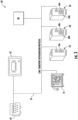
- the control system 60 may include a general user interface 62, such as a graphic user interface (GUI), a power control module (PCM) 64, and at least one module, such as a first module 66, a second module 68, a third module 70, and a fourth module 72.
- GUI graphic user interface
- PCM power control module
- the control system 60 is illustrated as having four modules, embodiments where the control system 60 has fewer than four modules, such as two modules, or three modules for example, or alternatively, more than four modules are also within the scope of the disclosure.
- the electronic refrigeration unit controller 50 is part of the control system 60 of the transport refrigeration system 20; for example, the first module 66 of FIG. 3 may include the electronic refrigeration unit controller 50.
- Each of the modules 66, 68, 70,and 72 may include at least one input connector (a) and/or at least one output connector (b). It should be understood that each module may include more than one input and output connector. Each input connector (a) may be keyed to accept an input functional device, and each output connector (b) may be keyed to accept an output functional device. Furthermore, it should be understood that each input connector (a) may be keyed to accept multiple input functional devices, and each output connector (b) may be keyed to accept multiple output functional devices. In an embodiment, one or more of the modules 66, 68, 70, 72 has enhanced diagnostic capabilities to identify if each module may be operating properly and if there is a problem, determine if the problem may be internal or external to the module.
- An interface bus 74 may operatively couple the components 62, 64, and/or modules 66, 68, 70, 72 of the control system 60. One or more of the plurality of modules 66, 68, 70, 72 is connectable to the CAN bus 74 via a port. Further, the interface bus 74 may include a power and ground wire for distributing power from the power control module 64 to the various modules 62, 66, 68, 70, and 72 connected to the interface bus 74. In an embodiment, the interface bus 74 includes a controller area network (CAN) bus for the modules 66, 68, 70, and 72 to communicate with each other. The CAN bus 74 may form a daisy chain that allows for direct and sequential communication between the modules 66, 68, 70, 72 without a host computer.
- CAN controller area network
- the transport refrigeration system 20 may include an engine emission system 76 including an exhaust treatment unit 80 having a diesel oxidation catalyst (DOC) 82 and a diesel particulate filter (DPF) 84 provided along the exhaust flow path, such as in-line with an exhaust pipe 86.
- the DOC 82 is configured to break down exhaust pollutants into less harmful substances, such as carbon dioxide and water for example, and the DPF 84 is configured to remove the particulates from the exhaust gas prior to the exhaust gas reaching the ambient atmosphere.
- the engine emission system 76 is operable to clean the exhaust flow path, such as by periodically cleaning the DPF 84 to remove accumulated soot and particles therefrom.
- an engine emission system 76 including an electronic engine controller 78 is optionally connectable to the CAN bus 74 as one of the plurality of modules. Accordingly, the engine controller 78 may be operably coupled to the refrigeration unit controller 50 via the CAN bus 74. The engine controller 78 is configured to initiate a cleaning operation in response to one or more monitored characteristics within the engine emission system.
- the engine emission system 76 is connectable to the CAN bus 74 using an engine emission system plug receivable within a corresponding engine emission system port 88, best shown in FIG. 5 . Because the engine emission system 76 is optional, in instances where the transport refrigeration system 20 does not include an engine emission system 76, a cap (not shown) may be installed or coupled to the engine emission system port 88. The cap may include one or more wires configured to complete the daisy chain of the CAN bus 74 when installed within the engine emission system port 88.
- a portable device 90 such as a laptop, CAN reader, or another piece of equipment capable of running a diagnostic and/or prognostic software may be directly connected to the CAN bus 74 in a manner similar to a module.
- a CAN adapter 100 is used to connect the portable device 90 to the CAN bus 74.
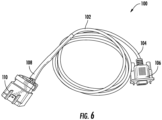
- An example of a CAN adapter 100 is shown in more detail in FIG. 6 .
- the CAN adapter 100 includes a cable 102 having a first connector 106 at a first end 104 thereof and a second connector 110 at a second, opposite end 108 thereof.
- the first connector 106 is a plug corresponding to a port formed on one or more types of portable devices 90.
- the first connector 106 is a standard nine pin serial male receivable within a corresponding nine pin serial female port or coupler.
- the portable device includes the serial male and the first connector 106 is the female, as well as other suitable connectors, are also within the scope of the disclosure.
- the second connector 110 may be receivable within the same port configured to receive the engine emission system 76.
- the second connector 110 arranged at the second end 108 of the cable 102 is complementary to and receivable within the engine emission system port 88.
- the second connector 110 may include a plurality of wires configured to complete the daisy chain of the CAN bus 74 when installed within the engine emission system port 88. Accordingly, the second connector 110 is interchangeable with the engine emission system cap and the engine emission system plug.
- the adapter 100 having a first and second connectors 104, 108 as described herein may be used to selectively connect a portable device to the CAN bus 74 of the control system 60.
- the portable device 90 By connecting the portable device to the engine emission system port 88, the portable device 90 is directly connected to the CAN bus 74 like a module of the control system 60.
- the portable device 90 is able not only to access the data in real time, but also to acquire substantially more data than would otherwise be attainable if a different type of connect, such as a universal serial bus (USB) for example, were used.
- USB universal serial bus
- the engine emission system port 88 has a different configuration than the ports configured to connect to and/or receive a connector of the other modules associated with the CAN bus 74.
- the engine emission system port 88 may have a configuration that is only capable of receiving a corresponding plug or connector in a specific orientation. As a result, by selecting the second connector 110 to mate with the engine emission system port 88, a mistakeproof connection may be formed between the second connector 110 and the CAN bus 74.
Landscapes
- Engineering & Computer Science (AREA)
- Physics & Mathematics (AREA)
- Mechanical Engineering (AREA)
- Thermal Sciences (AREA)
- Chemical & Material Sciences (AREA)
- Combustion & Propulsion (AREA)
- General Engineering & Computer Science (AREA)
- General Physics & Mathematics (AREA)
- Automation & Control Theory (AREA)
- Devices That Are Associated With Refrigeration Equipment (AREA)
Applications Claiming Priority (1)
| Application Number | Priority Date | Filing Date | Title |
|---|---|---|---|
| US202163241318P | 2021-09-07 | 2021-09-07 |
Publications (3)
| Publication Number | Publication Date |
|---|---|
| EP4144585A2 true EP4144585A2 (de) | 2023-03-08 |
| EP4144585A3 EP4144585A3 (de) | 2023-06-21 |
| EP4144585B1 EP4144585B1 (de) | 2026-02-25 |
Family
ID=83232577
Family Applications (1)
| Application Number | Title | Priority Date | Filing Date |
|---|---|---|---|
| EP22194397.0A Active EP4144585B1 (de) | 2021-09-07 | 2022-09-07 | Transportkältesystem |
Country Status (3)
| Country | Link |
|---|---|
| US (1) | US12560900B2 (de) |
| EP (1) | EP4144585B1 (de) |
| CN (1) | CN115771381A (de) |
Citations (1)
| Publication number | Priority date | Publication date | Assignee | Title |
|---|---|---|---|---|
| EP1226394B1 (de) * | 1999-11-03 | 2007-09-05 | Synchro Data Limited | Regelungssystem für gekühlte container |
Family Cites Families (22)
| Publication number | Priority date | Publication date | Assignee | Title |
|---|---|---|---|---|
| US5121854A (en) | 1990-01-16 | 1992-06-16 | Hobart Corporation | Apparatus for storing and dispensing frozen comestibles |
| DE19729105A1 (de) | 1997-07-08 | 1999-01-14 | Bosch Gmbh Robert | Einrichtung zur Übertragung von Daten |
| US6801942B1 (en) | 2000-09-15 | 2004-10-05 | Robert Bosch Gmbh | Apparatus, method and system for remotely accessing and/or controlling can node arrangements, including vehicle electronic control units, during vehicle operation |
| US6994073B2 (en) | 2003-10-31 | 2006-02-07 | Woodward Governor Company | Method and apparatus for detecting ionization signal in diesel and dual mode engines with plasma discharge system |
| DE102004034506B4 (de) | 2004-07-15 | 2006-05-04 | Inter Control Hermann Köhler Elektrik GmbH & Co. KG | CAN-Bus Adapter für drahtgebundene und wireless Kommunikation |
| EP2603840B1 (de) | 2010-08-13 | 2019-10-30 | Carrier Corporation | Flexibles und skalierbares modulares steuerungssystem für transportkühleinheiten |
| DE102011051758A1 (de) | 2011-07-12 | 2013-01-17 | Ipetronik Gmbh & Co. Kg | CAN-Bus-Adapter |
| US8818612B2 (en) * | 2011-09-14 | 2014-08-26 | Robert Bosch Gmbh | On-board diagnostic connector module and vehicle diagnostic system |
| CN202345583U (zh) | 2011-12-09 | 2012-07-25 | 綦江齿轮传动有限公司 | 汽车can总线适配电路 |
| CN102490669A (zh) | 2011-12-09 | 2012-06-13 | 綦江齿轮传动有限公司 | 汽车can总线适配电路及方法 |
| CN202974937U (zh) | 2012-12-17 | 2013-06-05 | 潍柴动力股份有限公司 | 一种发动机下线检测氮氧化物排放的系统 |
| CN102998355B (zh) | 2012-12-17 | 2016-01-13 | 潍柴动力股份有限公司 | 一种发动机下线检测氮氧化物排放的方法及系统 |
| EP3008402B1 (de) * | 2013-06-10 | 2018-08-01 | Thermo King Corporation | Einpunkt-kommunikationsschema für ein transportkühlsystem |
| CN203911182U (zh) | 2014-07-02 | 2014-10-29 | 广州旭诚信息科技有限公司 | 一种支持并发通讯的串口数据线 |
| US10924331B2 (en) | 2018-01-05 | 2021-02-16 | WeRide Corp. | Controller area network communication system |
| CN207925845U (zh) | 2018-03-06 | 2018-09-28 | 重庆恒芯天际科技有限公司 | 一种快速检测串口线 |
| EP3790750B1 (de) | 2018-05-09 | 2024-04-10 | Carrier Corporation | Energieverwaltung für transportkühleinheit |
| CN208707038U (zh) | 2018-05-31 | 2019-04-05 | 深圳市仁拓科技有限公司 | 读码器信号线 |
| US10954838B2 (en) | 2018-10-05 | 2021-03-23 | GM Global Technology Operations LLC | System and methods of integrated control of combustion and SCR systems |
| CN208903247U (zh) | 2018-10-25 | 2019-05-24 | 一汽-大众汽车有限公司 | 一种can总线适配器 |
| IT201900005278A1 (it) * | 2019-04-05 | 2020-10-05 | Arrowspot Systems Ltd | Trattamento a freddo a risposta attiva per carico refrigerato |
| CN113028667B (zh) | 2019-12-25 | 2024-12-06 | 开利公司 | 运输制冷系统以及用于运输制冷系统的can id分配方法 |
-
2022
- 2022-08-31 US US17/900,187 patent/US12560900B2/en active Active
- 2022-09-06 CN CN202211082446.4A patent/CN115771381A/zh active Pending
- 2022-09-07 EP EP22194397.0A patent/EP4144585B1/de active Active
Patent Citations (1)
| Publication number | Priority date | Publication date | Assignee | Title |
|---|---|---|---|---|
| EP1226394B1 (de) * | 1999-11-03 | 2007-09-05 | Synchro Data Limited | Regelungssystem für gekühlte container |
Also Published As
| Publication number | Publication date |
|---|---|
| EP4144585B1 (de) | 2026-02-25 |
| US12560900B2 (en) | 2026-02-24 |
| CN115771381A (zh) | 2023-03-10 |
| US20230077078A1 (en) | 2023-03-09 |
| EP4144585A3 (de) | 2023-06-21 |
Similar Documents
| Publication | Publication Date | Title |
|---|---|---|
| CN101600917B (zh) | 操作具有远程蒸发器的运输制冷单元的方法 | |
| RU2591105C2 (ru) | Способ эксплуатации транспортных холодильных систем, позволяющий избежать остановки двигателя и перегрузки | |
| CN112739964A (zh) | 制冷剂泄漏检测系统 | |
| US12077031B2 (en) | Variable speed for transport englineless refrigeration unit | |
| CN111971203A (zh) | 按照实时位置的自动运输制冷单元设置 | |
| EP4144585B1 (de) | Transportkältesystem | |
| US11667229B2 (en) | Natural gas tank pressure control for transport refrigeration unit | |
| US11976862B2 (en) | Electrical architecture for powering multiple transport refrigeration units | |
| EP3974217B1 (de) | Verfahren und systeme zur aufrechterhaltung der ladung bei einer extrem niedrigen temperatur über einen längeren zeitraum | |
| EP3668741B1 (de) | Gemeinsamer abgaskanal für transportkühleinheit und fahrzeug | |
| US20230287958A1 (en) | Vibration isolating bracket for exhaust treatment unit | |
| US20190162367A1 (en) | Method of improving compressed natural gas tank fill | |
| US20230271482A1 (en) | Transport refirgeration system for high ambient operation | |
| EP3719382B1 (de) | Aufwärmen des kraftstoffdruckreglers eines fahrzeugs durch ein kältemittel einer transportkälteeinheit | |
| US11619431B2 (en) | Method of defrosting a multiple heat absorption heat exchanger refrigeration system | |
| CN111936805A (zh) | 对制冷系统除霜的方法 | |
| US12017512B2 (en) | Crash detection system for transport refrigeration units | |
| CN121625723A (zh) | 具有多功率模式的运输制冷系统 | |
| HK1172943B (en) | Parameter control in transport refrigeration system and methods for same | |
| HK1172943A1 (zh) | 在運輸冷藏系統中的參數控制以及用於運輸冷藏系統的方法 |
Legal Events
| Date | Code | Title | Description |
|---|---|---|---|
| PUAI | Public reference made under article 153(3) epc to a published international application that has entered the european phase |
Free format text: ORIGINAL CODE: 0009012 |
|
| STAA | Information on the status of an ep patent application or granted ep patent |
Free format text: STATUS: THE APPLICATION HAS BEEN PUBLISHED |
|
| AK | Designated contracting states |
Kind code of ref document: A2 Designated state(s): AL AT BE BG CH CY CZ DE DK EE ES FI FR GB GR HR HU IE IS IT LI LT LU LV MC MK MT NL NO PL PT RO RS SE SI SK SM TR |
|
| PUAL | Search report despatched |
Free format text: ORIGINAL CODE: 0009013 |
|
| AK | Designated contracting states |
Kind code of ref document: A3 Designated state(s): AL AT BE BG CH CY CZ DE DK EE ES FI FR GB GR HR HU IE IS IT LI LT LU LV MC MK MT NL NO PL PT RO RS SE SI SK SM TR |
|
| RIC1 | Information provided on ipc code assigned before grant |
Ipc: B60H 1/32 20060101ALI20230515BHEP Ipc: H01R 31/06 20060101ALI20230515BHEP Ipc: B60P 3/20 20060101AFI20230515BHEP |
|
| STAA | Information on the status of an ep patent application or granted ep patent |
Free format text: STATUS: REQUEST FOR EXAMINATION WAS MADE |
|
| 17P | Request for examination filed |
Effective date: 20231220 |
|
| RBV | Designated contracting states (corrected) |
Designated state(s): AL AT BE BG CH CY CZ DE DK EE ES FI FR GB GR HR HU IE IS IT LI LT LU LV MC MK MT NL NO PL PT RO RS SE SI SK SM TR |
|
| REG | Reference to a national code |
Ref country code: DE Free format text: PREVIOUS MAIN CLASS: B60P0003200000 Ref country code: DE Ref legal event code: R079 Ref document number: 602022031014 Country of ref document: DE Free format text: PREVIOUS MAIN CLASS: B60P0003200000 Ipc: B60H0001000000 |
|
| RIC1 | Information provided on ipc code assigned before grant |
Ipc: H01R 31/06 20060101ALI20250801BHEP Ipc: B60H 1/32 20060101ALI20250801BHEP Ipc: B60H 1/00 20060101AFI20250801BHEP Ipc: B60P 3/20 20060101ALI20250801BHEP |
|
| GRAP | Despatch of communication of intention to grant a patent |
Free format text: ORIGINAL CODE: EPIDOSNIGR1 |
|
| STAA | Information on the status of an ep patent application or granted ep patent |
Free format text: STATUS: GRANT OF PATENT IS INTENDED |
|
| INTG | Intention to grant announced |
Effective date: 20250922 |
|
| GRAS | Grant fee paid |
Free format text: ORIGINAL CODE: EPIDOSNIGR3 |
|
| GRAA | (expected) grant |
Free format text: ORIGINAL CODE: 0009210 |
|
| STAA | Information on the status of an ep patent application or granted ep patent |
Free format text: STATUS: THE PATENT HAS BEEN GRANTED |
|
| AK | Designated contracting states |
Kind code of ref document: B1 Designated state(s): AL AT BE BG CH CY CZ DE DK EE ES FI FR GB GR HR HU IE IS IT LI LT LU LV MC MK MT NL NO PL PT RO RS SE SI SK SM TR |
|
| REG | Reference to a national code |
Ref country code: CH Ref legal event code: F10 Free format text: ST27 STATUS EVENT CODE: U-0-0-F10-F00 (AS PROVIDED BY THE NATIONAL OFFICE) Effective date: 20260225 Ref country code: GB Ref legal event code: FG4D |
|
| REG | Reference to a national code |
Ref country code: DE Ref legal event code: R096 Ref document number: 602022031014 Country of ref document: DE |
|
| REG | Reference to a national code |
Ref country code: IE Ref legal event code: FG4D Ref country code: NL Ref legal event code: FP |