EP4144274B1 - Cleaning apparatus system - Google Patents
Cleaning apparatus system Download PDFInfo
- Publication number
- EP4144274B1 EP4144274B1 EP21796866.8A EP21796866A EP4144274B1 EP 4144274 B1 EP4144274 B1 EP 4144274B1 EP 21796866 A EP21796866 A EP 21796866A EP 4144274 B1 EP4144274 B1 EP 4144274B1
- Authority
- EP
- European Patent Office
- Prior art keywords
- roller brush
- groove
- tray
- cleaning device
- cleaning apparatus
- Prior art date
- Legal status (The legal status is an assumption and is not a legal conclusion. Google has not performed a legal analysis and makes no representation as to the accuracy of the status listed.)
- Active
Links
Images



Classifications
-
- A—HUMAN NECESSITIES
- A47—FURNITURE; DOMESTIC ARTICLES OR APPLIANCES; COFFEE MILLS; SPICE MILLS; SUCTION CLEANERS IN GENERAL
- A47L—DOMESTIC WASHING OR CLEANING; SUCTION CLEANERS IN GENERAL
- A47L11/00—Machines for cleaning floors, carpets, furniture, walls, or wall coverings
- A47L11/40—Parts or details of machines not provided for in groups A47L11/02 - A47L11/38, or not restricted to one of these groups, e.g. handles, arrangements of switches, skirts, buffers, levers
-
- A—HUMAN NECESSITIES
- A47—FURNITURE; DOMESTIC ARTICLES OR APPLIANCES; COFFEE MILLS; SPICE MILLS; SUCTION CLEANERS IN GENERAL
- A47L—DOMESTIC WASHING OR CLEANING; SUCTION CLEANERS IN GENERAL
- A47L11/00—Machines for cleaning floors, carpets, furniture, walls, or wall coverings
- A47L11/40—Parts or details of machines not provided for in groups A47L11/02 - A47L11/38, or not restricted to one of these groups, e.g. handles, arrangements of switches, skirts, buffers, levers
- A47L11/4036—Parts or details of the surface treating tools
- A47L11/4041—Roll shaped surface treating tools
-
- A—HUMAN NECESSITIES
- A47—FURNITURE; DOMESTIC ARTICLES OR APPLIANCES; COFFEE MILLS; SPICE MILLS; SUCTION CLEANERS IN GENERAL
- A47L—DOMESTIC WASHING OR CLEANING; SUCTION CLEANERS IN GENERAL
- A47L11/00—Machines for cleaning floors, carpets, furniture, walls, or wall coverings
- A47L11/40—Parts or details of machines not provided for in groups A47L11/02 - A47L11/38, or not restricted to one of these groups, e.g. handles, arrangements of switches, skirts, buffers, levers
- A47L11/4091—Storing or parking devices, arrangements therefor; Means allowing transport of the machine when it is not being used
-
- A—HUMAN NECESSITIES
- A47—FURNITURE; DOMESTIC ARTICLES OR APPLIANCES; COFFEE MILLS; SPICE MILLS; SUCTION CLEANERS IN GENERAL
- A47L—DOMESTIC WASHING OR CLEANING; SUCTION CLEANERS IN GENERAL
- A47L9/00—Details or accessories of suction cleaners, e.g. mechanical means for controlling the suction or for effecting pulsating action; Storing devices specially adapted to suction cleaners or parts thereof; Carrying-vehicles specially adapted for suction cleaners
- A47L9/0009—Storing devices ; Supports, stands or holders
- A47L9/0063—External storing devices; Stands, casings or the like for the storage of suction cleaners
-
- A—HUMAN NECESSITIES
- A47—FURNITURE; DOMESTIC ARTICLES OR APPLIANCES; COFFEE MILLS; SPICE MILLS; SUCTION CLEANERS IN GENERAL
- A47L—DOMESTIC WASHING OR CLEANING; SUCTION CLEANERS IN GENERAL
- A47L9/00—Details or accessories of suction cleaners, e.g. mechanical means for controlling the suction or for effecting pulsating action; Storing devices specially adapted to suction cleaners or parts thereof; Carrying-vehicles specially adapted for suction cleaners
- A47L9/02—Nozzles
- A47L9/08—Nozzles with means adapted for blowing
-
- A—HUMAN NECESSITIES
- A47—FURNITURE; DOMESTIC ARTICLES OR APPLIANCES; COFFEE MILLS; SPICE MILLS; SUCTION CLEANERS IN GENERAL
- A47L—DOMESTIC WASHING OR CLEANING; SUCTION CLEANERS IN GENERAL
- A47L9/00—Details or accessories of suction cleaners, e.g. mechanical means for controlling the suction or for effecting pulsating action; Storing devices specially adapted to suction cleaners or parts thereof; Carrying-vehicles specially adapted for suction cleaners
- A47L9/28—Installation of the electric equipment, e.g. adaptation or attachment to the suction cleaner; Controlling suction cleaners by electric means
- A47L9/2836—Installation of the electric equipment, e.g. adaptation or attachment to the suction cleaner; Controlling suction cleaners by electric means characterised by the parts which are controlled
- A47L9/2847—Surface treating elements
-
- A—HUMAN NECESSITIES
- A47—FURNITURE; DOMESTIC ARTICLES OR APPLIANCES; COFFEE MILLS; SPICE MILLS; SUCTION CLEANERS IN GENERAL
- A47L—DOMESTIC WASHING OR CLEANING; SUCTION CLEANERS IN GENERAL
- A47L9/00—Details or accessories of suction cleaners, e.g. mechanical means for controlling the suction or for effecting pulsating action; Storing devices specially adapted to suction cleaners or parts thereof; Carrying-vehicles specially adapted for suction cleaners
- A47L9/28—Installation of the electric equipment, e.g. adaptation or attachment to the suction cleaner; Controlling suction cleaners by electric means
- A47L9/2868—Arrangements for power supply of vacuum cleaners or the accessories thereof
- A47L9/2873—Docking units or charging stations
Definitions
- the present invention relates to the technical field of machinery, and particularly to a tray and a cleaning apparatus system.
- a cleaning machine is a kind of cleaning device.
- a cleaning device also has its limitations, and any cleaning device should not appear in a using environment as a source of pollution.
- a cleaning machine in use often needs to be combined with water for cleaning. After a cleaning operation is completed, there is sewage remaining on a rolling brush on the cleaning machine.
- the cleaning machine is usually provided with a tray, through which the cleaning machine is stored, and liquid on the roller brush may flow into the tray.
- Prior art Document D1 ( CN110881900 A ) generally discloses a cleaning system and a base station of cleaning system, and specifically discloses that the base station comprises: a support platform for supporting a cleaning robot, the supporting platform has a cleaning tank with a top opening, the cleaning tank is used to containing water to clean the flanking cloth and/or rolling brush of a cleaning robot located above, the cleaning tank has a water inlet and a sewage discharge outlet; a drying component is used to generate hot air, and the drying component is connected to the cleaning tank; the hot air generated by the drying component is directed to the cleaning tank and the lint and/or rolling brush of the cleaning robot after drying and cleaning (see ABSTRACT of D1).
- Prior art Document D2 ( CN 209404651 U ) generally discloses a cleaning system and base station of cleaning system, and specifically discloses that the base station comprises a support table used for supporting a cleaning robot, the support table is provided with a cleaning tank with a top opening, the cleaning tank is used for containing water to clean lint and/or a rolling brush of the cleaning robot located above the cleaning tank, and the cleaning tank is provided with a water inlet and a sewage outlet; and the drying assembly is used for generating hot air, the drying assembly communicates with the cleaning tank, and the hot air generated by the drying assembly is guided into the cleaning tank so as to dry the cleaned flannelette and/or rolling brush of the cleaning robot (see ABSTRACT of D2).
- Prior art Document D3 ( CN 107752926 A ) generally discloses a service device for a wet cleaning device, and specifically discloses that the service device (1), in particular a base station, for carrying out a service treatment on a wet cleaning device (2) which can be connected to the service device (1); the service device comprises a device housing (3) has a receiving area (4) for receiving the wet cleaning device (2).
- the device housing (3) has a drying device (5) associated with the receiving area (4) for drying at least a partial area of the wet cleaning device (2) arranged in the receiving area (4) (see ABSTRACT of D3).
- Prior art Document D4 ( EP 3284382 A2 ) generally discloses a service device for a wet cleaning apparatus, and specifically discloses the service device (1), in particular a base station, for carrying out a service action on a wet cleaning device (2) that can be connected to the service device (1), which has a device housing (3) with a receiving area (4) for receiving a wet cleaning device (2) (see ABSTRACT of D4).
- the inventor found that, in the prior art, after a cleaning device completes cleaning, a roller brush is generally wet, the cleaning device needs to be stored on a tray, and then liquid on the roller brush may flow into the tray. In next use, the roller brush may still be wet with an odor.
- the applicant found a reason for the foregoing condition is that, after the cleaning device is disposed on the tray, part of the liquid on the roller brush may flow into the tray, while part still remains on the roller brush.
- the roller brush is kept in a humid environment for long time and unlikely to become dry within short time, which is prone to breeding of bacteria and production of odors. Consequently, the service life of the roller brush is shortened, and in addition, potential safety hazards are brought to the surrounding.
- the present invention provides a tray and a cleaning apparatus system.
- the tray performs drying treatment on a roller brush accommodation region and a roller brush in the roller brush accommodation region through a drying unit, to prevent the roller brush from being stored in a humid environment.
- FIG. 1 is a schematic structural diagram of a tray according to an embodiment of the present invention
- FIG. 2 is a schematic diagram of a sectional structure of a tray according to an embodiment of the present invention, as shown in FIGs. 1 and 2 .
- a tray including a tray body 10 and a drying unit 20.
- a roller brush accommodation region is arranged on an outer surface of the tray body 10.
- a mounting cavity 12 is provided in the tray body 10.
- the drying unit 20 is mounted in the mounting cavity 12. The drying unit 20 runs to perform drying treatment on the roller brush accommodation region and a roller brush in the roller brush accommodation region.
- the tray may be used with a cleaning device 30.
- the cleaning device includes, but not limited to, a cleaning machine.
- a roller brush 32 on the cleaning device 30 is located in the roller brush accommodation region, and the drying unit 20 runs to perform drying treatment on the roller brush accommodation region and the roller brush 32 in the roller brush accommodation region. Therefore, the roller brush 32 is prevented from being stored in a humid environment, breeding of bacteria and production of odors are reduced, the service life of the roller brush 32 is prolonged, and in addition, a strong guarantee is provided for user health.
- the tray may be used with a cleaning device 30.
- the cleaning device 30 includes a shell 31 and a roller brush 32 mounted to the shell 31.
- a space where the roller brush 32 is located is a roller brush cavity.
- a position of the roller brush accommodation region is adapted to that of the roller brush 32 of the cleaning device 30.
- the roller brush 32 of the cleaning device 30 is located in the roller brush accommodation region.
- the roller brush 32 of the cleaning device 30 includes, but not limited to, a lint roller brush 32. If liquid remains on the roller brush 32, part of the liquid may flow to the roller brush accommodation region, while part remains on the roller brush 32.
- the drying unit 20 may be turned on manually by a user or automatically to run to perform drying treatment on the roller brush accommodation region and the roller brush 32 in the roller brush accommodation region. After drying is completed, the roller brush accommodation region is dry, which preventing the roller brush 32 from being stored in a humid environment, and the roller brush 32 is still dry, which avoiding breeding of bacteria and production of odors.
- the tray may be used as an independent component.
- the tray is used with the cleaning device 30, and the cleaning device 30 and the tray are combined into a cleaning apparatus system.
- the tray may not only provide a storage function for the cleaning device 30 but also provide a charging function for the cleaning device 30.
- a charging pile 15 is further arranged on the tray body 10.
- the charging pile 15 may be electrically connected to a charging power supply.
- the tray may charge the cleaning device 30 through the charging pile 15 on the tray body 10.
- the charging pile 15 may also provide electric energy needed by the drying unit 20 to run.
- the cleaning device 30 in FIG. 3 includes a floor brush apparatus of the cleaning device 30.
- the roller brush 32 is arranged on the floor brush apparatus.
- Other components include, but not limited to, a handle, a clear water bucket, a recycling bucket, a main motor apparatus, etc.
- the cleaning device 30 includes, but not limited to, the cleaning device 30 shown in FIG. 3 , and also includes a self-moving cleaning robot, a handheld vacuum cleaner, a vertical cleaning device, etc.
- the cleaning device 30 described in the foregoing and following embodiments takes the cleaning device 30 shown in FIG. 3 as an example. It is to be noted that the description made taking the cleaning device 30 shown in FIG. 3 is merely an example and not intended to form improper limitations on the embodiment of the present invention.
- the drying unit 20 includes a heating apparatus 21, and a position of the heating apparatus 21 corresponds to that of the roller brush accommodation region.
- the heating apparatus 21 may be turned on automatically or manually by the user. After being turned on, the heating apparatus 21 may continuously heat the roller brush accommodation region.
- the heating apparatus 21 heats the roller brush accommodation region, water in the roller brush accommodation region and on the roller brush 32 in the roller brush accommodation region is gradually evaporated by heat, and water vapor is brought out by heat convection, so as to implement drying treatment of the roller brush accommodation region and the roller brush 32.
- the water vapor generated by heating may be brought out through a gap of the shell 31.
- the shell 31 of the cleaning device 30 includes a roller brush cover 33, and the roller brush cover 33 is arranged at an outer side of the roller brush 32 in a covering manner.
- an air vent 34 is formed in the roller brush cover 33. The water vapor may leave the roller brush cavity quickly through the air vent 34.
- the air vent 34 is formed at a position corresponding to the roller brush accommodation region. That is, the air vent 34 is located above the roller brush accommodation region. After the water is turned into water vapor by heating, the water vapor may rise gradually and be diffused to an external environment quickly from the air vent 34.
- the roller brush accommodation region may be arranged to be a plane structure, a slope structure, a curved structure, or a combination of one or more of these structures. Further, in order to accommodate the roller brush 32 better, the roller brush accommodation region is arranged to be a roller brush groove 11 shown in FIGs. 1, 2 , and 4 .
- the roller brush 32 on the cleaning device 30 is located in the roller brush groove 11, and a position of the drying unit 20 corresponds to that of the roller brush groove 11.
- the drying unit 20 runs to perform drying treatment on the roller brush groove 11 and the roller brush 32 in the roller brush groove 11.
- the position of the heating apparatus 21 corresponds to a groove bottom of the roller brush groove 11.
- the groove bottom of the roller brush groove 11 is a lowest point of the roller brush groove 11.
- the groove bottom of the roller brush groove 11 at least includes two inclined water collection plates.
- the inclined water collection plate is favorable for guiding water to the lowest point of the roller brush groove 11.
- a fall surface may be formed in the roller brush groove 11 through the water collection plate, and the water may be guided to the groove bottom of the roller brush groove 11 through the fall surface.
- the lowest point of the roller brush groove 11 corresponds to a bottom position of the roller brush 32.
- each of the two water collection plates is of a straight plate structure, and the two straight plate structures are connected to form a V-like shape with two higher sides and a lower middle, such that the water is convenient to guide to the bottom of the roller brush groove 11.
- the position of the heating apparatus 21 corresponds to the groove bottom of the roller brush groove 11, namely the heating apparatus 21 is located at the groove bottom of the roller brush groove 11, below the roller brush 32.
- the water accumulated at the groove bottom and below the roller brush 32 may be heated, so as to accelerate evaporation of the water.
- a heat outlet is formed in the roller brush groove 11 at a position corresponding to the heating apparatus 21. During heating by the heating apparatus 21, heat may be directly transferred into the roller brush groove 11 through the heat outlet. Therefore, the heat loss is reduced, and evaporation of the water is accelerated.
- a heat conduction water-stop plate 22 is arranged between the heating apparatus 21 and the heat outlet.
- the heat conduction water-stop plate 22 is made from, but not limited to, a metallic material, such as a stainless steel material and a galvanized plate material.
- the heating apparatus 21 is arranged below the roller brush 32, and then water may drop from the roller brush 32 that is yet not completely dry and enter the mounting cavity 12 below through the heat outlet, so that the tray body 10 is internally humid, and the heating apparatus 21 and the tray body 10 may be damaged.
- the heat conduction water-stop plate 22 may also transfer the heat of the heating apparatus 21 quickly to accelerate the evaporation of the water in the roller brush groove 11 and on the roller brush 32.
- the drying unit 20 includes an air outlet apparatus 23.
- the air outlet apparatus 23 includes, but not limited to, a fan.
- An air outlet 13 facing the roller brush accommodation region is formed in the tray body 10.
- a ventilation channel 14 is provided in the mounting cavity 12.
- the air outlet apparatus 23 is communicated with the air outlet 13 through the ventilation channel 14.
- the fan may be turned on automatically or manually by a user. After being turned on, the fan may push outside air into the mounting cavity 12 of the tray body 10. After entering the ventilation channel, airflow flows forward to the air outlet 13 along the ventilation channel, and then is blown into the roller brush accommodation region from the air outlet 13.
- the roller brush accommodation region may be arranged to be a plane structure, a slope structure, a curved structure, or a combination of one or more of these structures. Further, in order to accommodate the roller brush better, the roller brush accommodation region is arranged to be a roller brush groove 11 shown in FIGs. 1, 2 , and 6 .
- the roller brush groove 11 and the roller brush cover 33 form an airflow channel for airflow to flow through along an outer lateral surface of the roller brush 32.
- the airflow blown out of the air outlet 13 flows through the outer lateral surface of the roller brush 32 along the airflow channel to bring the water away from the roller brush 32.
- Air circulation in the roller brush groove 11 is improved by the airflow generated by the fan, so as to bring the water out through the airflow to implement air-drying treatment of the roller brush groove 11 and the roller brush 32.
- the airflow entering the roller brush groove 11 may be blown from the gap of the shell 31.
- the dashed line in FIGs. 6 and 7 indicates a flow path and direction of the airflow.
- an air vent 34 is formed in the roller brush cover 33.
- the water may leave the roller brush cavity quickly through the air vent 34.
- the dashed line in FIGs. 8 and 9 indicates a flow path and direction of the airflow.
- a position of the air outlet 13 may be set according to different air inlet requirements.
- the air outlet 13 is located in front of the roller brush groove 11 (referring to FIGs. 6 and 8 , namely the air outlet 13 is located at a left of the roller brush groove 11) and faces a groove opening of the roller brush groove 11, such that the airflow may enter the roller brush groove 11 from the groove opening of the roller brush groove 11.
- the air outlet 13 may be formed at a left side of the roller brush groove 11, i.e., a left-side position of the roller brush 32.
- the left-side position of the roller brush groove 11 is higher than the roller brush groove 11, so the water on the roller brush 32 that is yet not completely dry is prevented from entering the mounting cavity 12 from the air outlet.
- liquid such as water may be accumulated at the groove bottom of the roller brush groove 11, and the airflow enters the roller brush groove 11 from the groove opening at a higher position, so that the airflow has a higher impact, and may bring the water away from the roller brush groove 11 and the roller brush 32 along the airflow channel formed by the roller brush groove 11 and the roller brush cover 33.
- the air outlet 13 is located at a groove bottom of the roller brush groove 11, such that the airflow may enter the roller brush groove 11 from the groove bottom of the roller brush groove 11.
- the air outlet 13 may be formed at the bottom of the roller brush groove 11, i.e., a position below the roller brush 32. Therefore, the air outlet 13 is opposite to the groove bottom of the roller brush groove 11, and a flow path of the airflow is relatively short, effectively reducing the energy loss when the airflow flows.
- the airflow blown out of the air outlet 13 directly acts on the groove bottom of the roller brush groove 11 and the roller brush 32 with relatively high kinetic energy, and thus may bring the water away from the roller brush groove 11 and the roller brush 32 along the airflow channel formed by the roller brush groove 11 and the roller brush cover 33.
- the two setting modes for the air outlet may be implemented independently, or may be combined.
- the heating apparatus 21 and the air outlet apparatus 23 may be implemented independently, or may be combined. When they are combined, the heating apparatus 21 is located in the ventilation channel 14, namely the heating apparatus 21 is located on the flow path of the airflow, hot air is formed after the airflow generated by the air outlet apparatus 23 passes through the heating apparatus 21, and drying treatment of the roller brush accommodation region and the roller brush 32 may be completed quickly under the heating action of the heating apparatus 21 and the air-drying action of the hot air.
- the air vent 34 is formed in the roller brush cover 33, or the air vent 34 is not formed. When the air vent 34 is not formed, the water or the water vapor may be diffused from a combination gap of the roller brush cover 33 and the tray or the gap of the shell 31.
- the drying unit 20 may be turned on manually by the user or automatically according to a triggering condition.
- the tray further includes a detection unit and a control unit.
- the control unit is electrically connected with the detection unit and the drying unit 20 respectively.
- the control unit controls the drying unit 20 to run when the detection unit detects a triggering event.
- the control unit may be arranged in the charging pile 15.
- the detection unit may be arranged in the charging pile 15 or on the tray body 10 according to different requirements.
- the detection unit includes, but not limited to, a pressure sensor, a light sensor, and a magnetic induction sensor.
- the tray further includes a timing unit.
- the timing unit is electrically connected with the control unit.
- the control unit controls the timing unit to run while controlling the drying unit 20 to run.
- the control unit controls the drying unit 20 to be turned off when a timing length of the timing unit is equal to preset time.
- the user may preset running time of the drying unit 20, i.e., the preset time.
- the preset time represents time from the beginning to end of each running of the drying unit 20.
- the control unit controls the timing unit to start timing when controlling the drying unit 20 to start to run, and controls the drying unit 20 to stop when the timing length of the timing unit is equal to the preset time, so as to complete a drying operation.
- the preset time of the timing unit may be preset by the user according to different drying requirements. For example, when the roller brush 32 is a lint roller brush with strong water absorption, relatively long drying time is needed, and the user may set relatively long preset time. When the roller brush 32 is a bristle roller brush with weak water absorption, relatively short drying time is needed, and the user may set relatively short preset time.
- the tray further includes a charging unit.
- the tray may perform drying treatment on the roller brush 32 on the cleaning device 30 while charging the cleaning device 30 to realize two functions at the same time. Therefore, preparations of the cleaning device 30 may be completed quickly to save time for a next cleaning operation.
- a method for performing drying treatment by use of the tray includes the following steps.
- step 1 the tray is turned on, or the tray is connected to a power supply to automatically enter a standby state.
- step 2 the detection unit detects whether the cleaning device 30 is disposed on the tray. If YES, step 3 continues to be performed. If NO, no processing is performed, or the process is ended.
- step 3 the control unit controls the drying unit 20 to run.
- the method for performing drying treatment by use of the tray may further include the following steps (referring to FIG. 10 ).
- step 4 whether the timing length of the timing unit is equal to the preset time is determined. If YES, step 5 is performed. If NO, step 3 continues to be performed.
- step 5 the control unit turns off the drying unit 20, and the process is ended.
- the tray may be used with the cleaning device 30.
- the cleaning device 30 When the cleaning device 30 is disposed on the tray, the roller brush 32 on the cleaning device 30 is located in the roller brush groove 11, and the drying unit 20 runs to perform drying treatment on the roller brush groove 11 and the roller brush 32 in the roller brush groove 11. Therefore, the roller brush 32 is prevented from being stored in a humid environment, breeding of bacteria and production of odors are reduced, the service life of the roller brush 32 is prolonged, and in addition, a strong guarantee is provided for user health.
- the embodiments of the present invention disclose embodiment 2.
- the embodiments of the present invention provide a cleaning apparatus system, including a cleaning device 30 and a tray.
- the tray may be implemented by the tray as mentioned in one possible implement.
- a specific solution is as follows.
- the embodiments of the present invention also provide a cleaning apparatus system, including a cleaning device 30 and a tray.
- the cleaning device 30 includes a shell 31 and a roller brush 32 mounted to the shell 31.
- the tray includes a tray body 10 and a drying unit 20.
- the tray body 10 is provided with a roller brush accommodation region.
- the roller brush 32 is located in the roller brush accommodation region when the cleaning device 30 is disposed on the tray.
- a mounting cavity 12 is provided in the tray body 10.
- the drying unit 20 is mounted in the mounting cavity 12. The drying unit 20 runs to perform drying treatment on the roller brush accommodation region and the roller brush 32 in the roller brush accommodation region.
- the cleaning device 30 may be disposed on the tray, and the tray provides a storage function for the cleaning device 30.
- the roller brush 32 on the cleaning device 30 is located in the roller brush accommodation region, and the drying unit 20 runs to perform drying treatment on the roller brush accommodation region and the roller brush 32 in the roller brush accommodation region. Therefore, the roller brush 32 is prevented from being stored in a humid environment, breeding of bacteria and production of odors are reduced, the service life of the roller brush 32 is prolonged, and in addition, a strong guarantee is provided for user health.
- the drying unit 20 includes a heating apparatus 21, and a position of the heating apparatus 21 corresponds to that of the roller brush accommodation region.
- the heating apparatus 21 may be turned on automatically or manually by the user. After being turned on, the heating apparatus 21 may continuously heat the roller brush accommodation region.
- the heating apparatus 21 heats the roller brush accommodation region, water in the roller brush accommodation region and on the roller brush 32 is gradually evaporated by heat, and water vapor is brought out by heat convection, so as to implement drying treatment of the roller brush accommodation region and the roller brush 32.
- the water vapor generated by heating may be brought out through a gap of the shell 31.
- the drying unit 20 includes an air outlet apparatus 23.
- the air outlet apparatus 23 includes, but not limited to, a fan.
- An air outlet 13 facing the roller brush accommodation region is formed in the tray body 10.
- a ventilation channel 14 is provided in the mounting cavity 12.
- the air outlet apparatus 23 is communicated with the air outlet 13 through the ventilation channel 14. Taking a fan as an example, when the cleaning device 30 is disposed on the tray body 10 after completing cleaning, the fan may be turned on automatically or manually by a user. After being turned on, the fan may push outside air into the mounting cavity 12 of the tray body 10.
- Air circulation in the roller brush accommodation region is improved by the airflow generated by the fan, so as to bring the water out through the airflow to implement air-drying treatment of the roller brush accommodation region and the roller brush 32.
- the airflow entering the roller brush accommodation region may be blown from the gap of the shell 31.
- the dashed line in FIGs. 6 and 7 indicates a flow path and direction of the airflow.
- the shell 31 includes a roller brush cover 33, and the roller brush cover 33 is arranged at an outer side of the roller brush 32 in a covering manner.
- the roller brush groove 11 and the roller brush cover 33 form an airflow channel for airflow to flow through along an outer lateral surface of the roller brush 32.
- the drying unit 20 performs drying treatment, the water may be brought away from the airflow channel.
- an air vent 34 is formed in the roller brush cover 33 at a position opposite to the roller brush groove 11.
- the water vapor may leave the roller brush cavity quickly through the air vent 34.
- the air vent 34 is formed at a position corresponding to the roller brush groove 11. That is, the air vent 34 is located above the roller brush groove 11.
- drying treatment may be performed on the roller brush 32 through a suction component in the cleaning device 30, to dry the roller brush 32 quickly and prevent the roller brush 32 from getting moldy and smelly.
- a suction component is further arranged in the shell 31.
- the suction component may include, but not limited to, a main motor and a fan blade.
- the cleaning device 30 is further provided with a suction port in airflow communication with the suction component.
- the suction port is arranged at a bottom of the shell 31.
- the suction port is located in the roller brush groove 11 when the roller brush 32 is located in the roller brush groove 11.
- the suction component runs to perform drying treatment on the roller brush groove 11 and the roller brush in the roller brush groove 11.
- the suction component may work in two modes. One is a normal working mode. In the normal working mode, the suction component works with relatively high power to complete a cleaning operation on a surface to be cleaned. The other is a drying working mode. In the drying working mode, the suction component works with relatively low power to complete drying treatment of the roller brush 32.
- the suction port is located in the roller brush 11, and the suction component runs in the drying working mode with relatively low power.
- the suction component is controlled to run with power of more a dozen watts and even a few watts. Therefore, the suction component may run with a relatively low voltage and current, and a generated noise is low.
- the suction component drives the airflow to flow to perform air-drying treatment on the roller brush 32, air duct, and other components in a relatively closed environment, thereby avoiding mildews and odors and prolonging the service life of the machine.
- the suction component runs with relatively low power, so that electric energy waste and long-term noises are avoided.
- the technical features of the tray as mentioned in embodiment 2 may refer to the implementation modes of the tray in one possible implement, related technical features in embodiment 2 may refer to those in one possible implement, and elaborations are omitted herein.
- the embodiments of the present invention disclose embodiment 3.
- the embodiments of the present invention provide a cleaning apparatus system, including a cleaning device 30 and a tray.
- Implementation modes of the cleaning device 30 and the tray may refer to those of the cleaning device 30 and tray as mentioned in one possible implement and embodiment 2.
- a specific solution is as follows.
- the embodiments of the present invention also provide a cleaning apparatus system, including a cleaning device 30, a tray, and a drying unit.
- the cleaning device 30 includes a roller brush 32.
- the tray includes a tray body 10.
- the tray body 10 includes a roller brush accommodation region and a mounting cavity 12.
- the drying unit 20 is arranged in the mounting cavity 12. The drying unit 20 runs to perform drying treatment on the roller brush accommodation region and the roller brush 32 in the roller brush accommodation region.
- the cleaning device 30 may be disposed on the tray, and the tray provides a storage function for the cleaning device 30.
- the roller brush 32 on the cleaning device 30 is located in the roller brush accommodation region, and the drying unit 20 runs to perform drying treatment on the roller brush accommodation region and the roller brush 32 in the roller brush accommodation region. Therefore, the roller brush 32 is prevented from being stored in a humid environment, breeding of bacteria and production of odors are reduced, the service life of the roller brush 32 is prolonged, and in addition, a strong guarantee is provided for user health.
- the technical features of the cleaning device 30, tray, and drying unit 20 as mentioned in embodiment 3 may refer to the implementation modes of the cleaning device 30, tray, and drying unit 20 in one possible implement and embodiment 2, related technical features in embodiment 3 may refer to those in one possible implement and embodiment 2, and elaborations are omitted herein.
- the embodiments of the present invention disclose another possible implement.
- the embodiments of the present invention provide a base station, including a base station body and a drying unit 20.
- the base station body includes a roller brush accommodation region and a mounting cavity 12.
- the drying unit 20 is arranged in the mounting cavity 12.
- the drying unit 20 runs to perform drying treatment on the roller brush accommodation region and a roller brush 32 in the roller brush accommodation region.
- the technical features of the base station body and drying unit 20 as mentioned in another possible implement may refer to the implementation modes of the base station body and drying unit 20 in one possible implement and embodiment 2, related technical features in another possible implement may refer to those in one possible implement to embodiment 3, and elaborations are omitted herein.
- the embodiments of the present invention disclose embodiment 5.
- the embodiments of the present invention provide a cleaning apparatus system, including a cleaning device 30 and a tray.
- Implementation modes of the cleaning device 30 and the tray may refer to those of the cleaning device 30 and tray as mentioned in one possible implement and embodiment 2.
- a specific solution is as follows.
- a cleaning apparatus system includes a cleaning device 30 and a tray.
- the cleaning device 30 includes a roller brush 32.
- the tray includes a tray body 10.
- the tray body 10 is provided with a roller brush accommodation region.
- a mounting cavity 12 is provided in the tray body 10.
- a drying unit 20 is arranged in the mounting cavity 12. When the cleaning device 30 is located on the tray body 10, the roller brush 32 is located in the roller brush accommodation region, and the drying unit 20 is aligned with the roller brush accommodation region and the roller brush 32.
- the drying unit 20 runs to perform drying treatment on the roller brush accommodation region and the roller brush 32.
- the technical features of the cleaning device 30 and tray as mentioned in embodiment 5 may refer to the implementation modes of the cleaning device 30 and tray in one possible implement to another possible implement, related technical features in embodiment 5 may refer to those in one possible implement to another possible implement, and elaborations are omitted herein.
- the cleaning device may be stored in the tray, through which a storage and charging functions may be provided for the cleaning device.
- the roller brush of the cleaning device is located in the roller brush groove.
- the drying unit may be turned on manually by a user or automatically to run.
- the drying unit is a heating apparatus. After being turned on, the heating apparatus may continuously heat the roller brush groove. When the heating apparatus heats the roller brush groove, water in the roller brush groove and on the roller brush is gradually evaporated by heat, and water vapor is separated from the roller brush and brought out by heat convection, so as to implement drying treatment of the roller brush groove and the roller brush.
- the water vapor generated by heating may be brought out through a gap of the shell.
- the cleaning device may be stored in the tray, through which a storage and charging functions may be provided for the cleaning device.
- the roller brush of the cleaning device is located in the roller brush groove.
- the drying unit may be turned on manually by a user or automatically to run.
- the drying unit is a fan. After being turned on, the fan may push outside air into the mounting cavity of the tray body. After entering the ventilation channel, airflow flows forward to the air outlet along the ventilation channel, and then is blown into the roller brush groove from the air outlet.
- the air outlet may be formed in front of the roller brush groove, and faces the groove opening of the roller brush groove. Alternatively, the air outlet is located at the groove bottom of the roller brush groove.
- the roller brush groove and the roller brush cover form an airflow channel for airflow to flow through along an outer lateral surface of the roller brush.
- the airflow blown out of the air outlet flows through the outer lateral surface of the roller brush along the airflow channel to bring the water away from the roller brush.
- Air circulation in the roller brush groove is improved by the airflow generated by the fan, so as to bring the water out through the airflow to implement air-drying treatment of the roller brush groove and the roller brush.
- An air vent is formed in the roller brush cover of the cleaning device.
- the water vapor may rise gradually to leave the roller brush cavity quickly through the air vent and be diffused to an external environment quickly.
- the airflow generated by the fan flows through the outer lateral surface of the roller brush along the airflow channel, and is blown out of the air vent quickly to bring the water away from the roller brush.
- the suction port is located in the roller brush.
- the suction component may be selected manually or automatically to run in the drying working mode. In this mode, running power of the suction component is relatively low. For example, the suction component is controlled to run with power of more a dozen watts and even a few watts. Therefore, the suction component may run with a relatively low voltage and current, and a generated noise is low.
- the suction component drives the airflow to flow to perform air-drying treatment on the roller brush, air duct, and other components in a relatively closed environment.
Landscapes
- Engineering & Computer Science (AREA)
- Mechanical Engineering (AREA)
- Robotics (AREA)
- Cleaning In General (AREA)
Description
- The present invention relates to the technical field of machinery, and particularly to a tray and a cleaning apparatus system.
- With the development of social productivity, people's living standard has also been improved. With the material basis guaranteed, people begin to use a variety of tools to reduce labor and further improve the quality of life. Cleaning device comes into being. For example, a cleaning machine is a kind of cleaning device. Currently, a cleaning device also has its limitations, and any cleaning device should not appear in a using environment as a source of pollution.
- At present, a cleaning machine in use often needs to be combined with water for cleaning. After a cleaning operation is completed, there is sewage remaining on a rolling brush on the cleaning machine. In order to prevent sewage from flowing to the ground and other cleaning surfaces, the cleaning machine is usually provided with a tray, through which the cleaning machine is stored, and liquid on the roller brush may flow into the tray.
- However, when an existing tray is used with a cleaning machine, part of sewage on a roller brush flow into the tray, while part still remains on the roller brush. As a result, the roller brush is kept in a humid environment for long time, which is prone to breeding of bacteria and production of odors. Consequently, the service life of the roller brush is shortened, and in addition, potential safety hazards are brought to the surrounding.
- Prior art Document D1 (
CN110881900 A ) generally discloses a cleaning system and a base station of cleaning system, and specifically discloses that the base station comprises: a support platform for supporting a cleaning robot, the supporting platform has a cleaning tank with a top opening, the cleaning tank is used to containing water to clean the flanking cloth and/or rolling brush of a cleaning robot located above, the cleaning tank has a water inlet and a sewage discharge outlet; a drying component is used to generate hot air, and the drying component is connected to the cleaning tank; the hot air generated by the drying component is directed to the cleaning tank and the lint and/or rolling brush of the cleaning robot after drying and cleaning (see ABSTRACT of D1). - Prior art Document D2 (
CN 209404651 U ) generally discloses a cleaning system and base station of cleaning system, and specifically discloses that the base station comprises a support table used for supporting a cleaning robot, the support table is provided with a cleaning tank with a top opening, the cleaning tank is used for containing water to clean lint and/or a rolling brush of the cleaning robot located above the cleaning tank, and the cleaning tank is provided with a water inlet and a sewage outlet; and the drying assembly is used for generating hot air, the drying assembly communicates with the cleaning tank, and the hot air generated by the drying assembly is guided into the cleaning tank so as to dry the cleaned flannelette and/or rolling brush of the cleaning robot (see ABSTRACT of D2). - Prior art Document D3 (
CN 107752926 A ) generally discloses a service device for a wet cleaning device, and specifically discloses that the service device (1), in particular a base station, for carrying out a service treatment on a wet cleaning device (2) which can be connected to the service device (1); the service device comprises a device housing (3) has a receiving area (4) for receiving the wet cleaning device (2). In order to provide a further functionality of the service device (1), it is proposed that the device housing (3) has a drying device (5) associated with the receiving area (4) for drying at least a partial area of the wet cleaning device (2) arranged in the receiving area (4) (see ABSTRACT of D3). - Prior art Document D4 (
EP 3284382 A2 ) generally discloses a service device for a wet cleaning apparatus, and specifically discloses the service device (1), in particular a base station, for carrying out a service action on a wet cleaning device (2) that can be connected to the service device (1), which has a device housing (3) with a receiving area (4) for receiving a wet cleaning device (2) (see ABSTRACT of D4). - In view of the foregoing problems, embodiments of the present invention are disclosed to provide a tray and cleaning apparatus system for solving the foregoing problems. The invention is set out in the appended set of claims
- In order to describe the technical solutions in the embodiments of the present invention or the prior art more clearly, the drawings required to be used in descriptions about the embodiments or the prior art will be introduced briefly below. Apparently, the drawings in the description below are some embodiments of the present invention. Those of ordinary skill in the art may further obtain other drawings according to these drawings without creative work.
-
FIG. 1 is a schematic structural diagram of a tray according to an embodiment of the present invention; -
FIG. 2 is a schematic diagram of a sectional structure of a tray according to an embodiment of the present invention; -
FIG. 3 is a schematic section view when a tray is used with a cleaning device according to an embodiment of the present invention; -
FIG. 4 is a schematic enlarged view of part A inFIG. 3 , a schematic diagram of a sectional structure when a drying unit includes a heating apparatus; -
FIG. 5 is a schematic enlarged view of part A inFIG. 3 , a schematic diagram of a sectional structure when a heat conduction water-stop plate is arranged on the tray; -
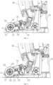
FIG. 6 is a schematic enlarged view of part A inFIG. 3 , a schematic diagram of a sectional structure when a drying unit includes an air outlet apparatus and an air outlet is located in front of a roller brush groove; -
FIG. 7 is a schematic enlarged view of part A inFIG. 3 , a schematic diagram of a sectional structure when a drying unit includes an air outlet apparatus and an air outlet is located at a bottom of a roller brush groove (not part of the claimed invention); -
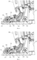
FIG. 8 is a schematic enlarged view of part A inFIG. 3 , a schematic diagram of a sectional structure when a drying unit includes an air outlet apparatus, an air outlet is located in front of a roller brush groove, and an air vent is formed in a shell of the cleaning device; -
FIG. 9 is a schematic enlarged view of part A inFIG. 3 , a schematic diagram of a sectional structure when a drying unit includes an air outlet apparatus, an air outlet is located at a bottom of a roller brush groove, and an air vent is formed in a shell of the cleaning device (not part of the claimed invention); and -
FIG. 10 is a schematic running flowchart of a tray according to an embodiment of the present invention. - In order to enable those skilled in the art to understand the solutions of the present invention better, the technical solutions in the embodiments of the present invention will be described clearly and completely below in combination with the drawings in the embodiments of the present invention.
- In the practice of the embodiments of the present invention, the inventor found that, in the prior art, after a cleaning device completes cleaning, a roller brush is generally wet, the cleaning device needs to be stored on a tray, and then liquid on the roller brush may flow into the tray. In next use, the roller brush may still be wet with an odor.
- The applicant found a reason for the foregoing condition is that, after the cleaning device is disposed on the tray, part of the liquid on the roller brush may flow into the tray, while part still remains on the roller brush. As a result, the roller brush is kept in a humid environment for long time and unlikely to become dry within short time, which is prone to breeding of bacteria and production of odors. Consequently, the service life of the roller brush is shortened, and in addition, potential safety hazards are brought to the surrounding.
- For the foregoing problems, the present invention provides a tray and a cleaning apparatus system. The tray performs drying treatment on a roller brush accommodation region and a roller brush in the roller brush accommodation region through a drying unit, to prevent the roller brush from being stored in a humid environment.
- The technical solutions in the embodiments of the present invention will be described clearly and completely below in combination with the drawings in the embodiments of the present invention. Apparently, the described embodiments are not all but only part of embodiments of the present invention. All other embodiments obtained by those skilled in the art based on the embodiments in the present invention without creative work shall fall within the scope of protection of the present invention.
-
FIG. 1 is a schematic structural diagram of a tray according to an embodiment of the present invention, andFIG. 2 is a schematic diagram of a sectional structure of a tray according to an embodiment of the present invention, as shown inFIGs. 1 and 2 . - In an embodiment of the present invention, a tray is provided, including a
tray body 10 and adrying unit 20. A roller brush accommodation region is arranged on an outer surface of thetray body 10. Amounting cavity 12 is provided in thetray body 10. Thedrying unit 20 is mounted in themounting cavity 12. Thedrying unit 20 runs to perform drying treatment on the roller brush accommodation region and a roller brush in the roller brush accommodation region. - According to the technical solution provided in the embodiment of the present invention, referring to
FIGs. 3 and4 , the tray may be used with acleaning device 30. - The cleaning device includes, but not limited to, a cleaning machine. When the
cleaning device 30 is disposed on the tray, aroller brush 32 on thecleaning device 30 is located in the roller brush accommodation region, and thedrying unit 20 runs to perform drying treatment on the roller brush accommodation region and theroller brush 32 in the roller brush accommodation region. Therefore, theroller brush 32 is prevented from being stored in a humid environment, breeding of bacteria and production of odors are reduced, the service life of theroller brush 32 is prolonged, and in addition, a strong guarantee is provided for user health. - For example, referring to
FIGs. 3 and4 , in the embodiment of the present invention, the tray may be used with acleaning device 30. Thecleaning device 30 includes ashell 31 and aroller brush 32 mounted to theshell 31. A space where theroller brush 32 is located is a roller brush cavity. A position of the roller brush accommodation region is adapted to that of theroller brush 32 of thecleaning device 30. When thecleaning device 30 is disposed on thetray body 10, theroller brush 32 of thecleaning device 30 is located in the roller brush accommodation region. Theroller brush 32 of thecleaning device 30 includes, but not limited to, alint roller brush 32. If liquid remains on theroller brush 32, part of the liquid may flow to the roller brush accommodation region, while part remains on theroller brush 32. The dryingunit 20 may be turned on manually by a user or automatically to run to perform drying treatment on the roller brush accommodation region and theroller brush 32 in the roller brush accommodation region. After drying is completed, the roller brush accommodation region is dry, which preventing theroller brush 32 from being stored in a humid environment, and theroller brush 32 is still dry, which avoiding breeding of bacteria and production of odors. - It is to be noted that, in the embodiment of the present invention, the tray may be used as an independent component. Alternatively, as shown in
FIG. 3 , the tray is used with thecleaning device 30, and thecleaning device 30 and the tray are combined into a cleaning apparatus system. The tray may not only provide a storage function for thecleaning device 30 but also provide a charging function for thecleaning device 30. A chargingpile 15 is further arranged on thetray body 10. The chargingpile 15 may be electrically connected to a charging power supply. The tray may charge thecleaning device 30 through the chargingpile 15 on thetray body 10. The chargingpile 15 may also provide electric energy needed by the dryingunit 20 to run. - The
cleaning device 30 inFIG. 3 includes a floor brush apparatus of thecleaning device 30. Theroller brush 32 is arranged on the floor brush apparatus. Other components include, but not limited to, a handle, a clear water bucket, a recycling bucket, a main motor apparatus, etc. In the embodiment of the present invention, thecleaning device 30 includes, but not limited to, thecleaning device 30 shown inFIG. 3 , and also includes a self-moving cleaning robot, a handheld vacuum cleaner, a vertical cleaning device, etc. Thecleaning device 30 described in the foregoing and following embodiments takes thecleaning device 30 shown inFIG. 3 as an example. It is to be noted that the description made taking thecleaning device 30 shown inFIG. 3 is merely an example and not intended to form improper limitations on the embodiment of the present invention. - In the embodiment of the present invention, there are many implementation modes of the drying
unit 20. Referring back toFIG. 4 , as an implementation mode of the dryingunit 20, the dryingunit 20 includes aheating apparatus 21, and a position of theheating apparatus 21 corresponds to that of the roller brush accommodation region. When thecleaning device 30 is disposed on thetray body 10 after completing cleaning, theheating apparatus 21 may be turned on automatically or manually by the user. After being turned on, theheating apparatus 21 may continuously heat the roller brush accommodation region. When theheating apparatus 21 heats the roller brush accommodation region, water in the roller brush accommodation region and on theroller brush 32 in the roller brush accommodation region is gradually evaporated by heat, and water vapor is brought out by heat convection, so as to implement drying treatment of the roller brush accommodation region and theroller brush 32. The water vapor generated by heating may be brought out through a gap of theshell 31. - Further, the
shell 31 of thecleaning device 30 includes aroller brush cover 33, and theroller brush cover 33 is arranged at an outer side of theroller brush 32 in a covering manner. In order to make it convenient for the water vapor to leave the roller brush cavity quickly, anair vent 34 is formed in theroller brush cover 33. The water vapor may leave the roller brush cavity quickly through theair vent 34. Furthermore, theair vent 34 is formed at a position corresponding to the roller brush accommodation region. That is, theair vent 34 is located above the roller brush accommodation region. After the water is turned into water vapor by heating, the water vapor may rise gradually and be diffused to an external environment quickly from theair vent 34. Specifically, the roller brush accommodation region may be arranged to be a plane structure, a slope structure, a curved structure, or a combination of one or more of these structures. Further, in order to accommodate theroller brush 32 better, the roller brush accommodation region is arranged to be aroller brush groove 11 shown inFIGs. 1, 2 , and4 . When thecleaning device 30 is disposed on the tray, theroller brush 32 on thecleaning device 30 is located in theroller brush groove 11, and a position of the dryingunit 20 corresponds to that of theroller brush groove 11. The dryingunit 20 runs to perform drying treatment on theroller brush groove 11 and theroller brush 32 in theroller brush groove 11. - Referring back to
FIG. 4 , in a possible embodiment of the present invention, the position of theheating apparatus 21 corresponds to a groove bottom of theroller brush groove 11. In order to better collect the water flowing from theroller brush 32, the groove bottom of theroller brush groove 11 is a lowest point of theroller brush groove 11. As an implementation mode of theroller brush groove 11, the groove bottom of theroller brush groove 11 at least includes two inclined water collection plates. The inclined water collection plate is favorable for guiding water to the lowest point of theroller brush groove 11. A fall surface may be formed in theroller brush groove 11 through the water collection plate, and the water may be guided to the groove bottom of theroller brush groove 11 through the fall surface. The lowest point of theroller brush groove 11 corresponds to a bottom position of theroller brush 32. For example, each of the two water collection plates is of a straight plate structure, and the two straight plate structures are connected to form a V-like shape with two higher sides and a lower middle, such that the water is convenient to guide to the bottom of theroller brush groove 11. The position of theheating apparatus 21 corresponds to the groove bottom of theroller brush groove 11, namely theheating apparatus 21 is located at the groove bottom of theroller brush groove 11, below theroller brush 32. During heating by theheating apparatus 21, the water accumulated at the groove bottom and below theroller brush 32 may be heated, so as to accelerate evaporation of the water. - Further, in order to transfer the heat more quickly into the
roller brush groove 11, in a possible embodiment of the present invention, a heat outlet is formed in theroller brush groove 11 at a position corresponding to theheating apparatus 21. During heating by theheating apparatus 21, heat may be directly transferred into theroller brush groove 11 through the heat outlet. Therefore, the heat loss is reduced, and evaporation of the water is accelerated. - Furthermore, in order to prevent the water on the
roller brush 32 and in theroller brush groove 11 from entering the mountingcavity 12 through the heat outlet to damage theheating apparatus 21, referring toFIG. 5 , a heat conduction water-stop plate 22 is arranged between theheating apparatus 21 and the heat outlet. The heat conduction water-stop plate 22 is made from, but not limited to, a metallic material, such as a stainless steel material and a galvanized plate material. Theheating apparatus 21 is arranged below theroller brush 32, and then water may drop from theroller brush 32 that is yet not completely dry and enter the mountingcavity 12 below through the heat outlet, so that thetray body 10 is internally humid, and theheating apparatus 21 and thetray body 10 may be damaged. With the arrangement of the heat conduction water-stop plate 22 above theheating apparatus 21, liquid such as water may be effectively prevented from entering the mountingcavity 12 through the heat outlet. In addition, the heat conduction water-stop plate 22 may also transfer the heat of theheating apparatus 21 quickly to accelerate the evaporation of the water in theroller brush groove 11 and on theroller brush 32. - In the embodiment of the present invention, there is another implementation mode of the drying
unit 20, besides the foregoing implementation of the dryingunit 20 by theheating apparatus 21. Referring toFIGs. 6 and 7 , the dryingunit 20 includes anair outlet apparatus 23. Theair outlet apparatus 23 includes, but not limited to, a fan. Anair outlet 13 facing the roller brush accommodation region is formed in thetray body 10. Aventilation channel 14 is provided in the mountingcavity 12. Theair outlet apparatus 23 is communicated with theair outlet 13 through theventilation channel 14. Taking a fan as an example, when thecleaning device 30 is disposed on thetray body 10 after completing cleaning, the fan may be turned on automatically or manually by a user. After being turned on, the fan may push outside air into the mountingcavity 12 of thetray body 10. After entering the ventilation channel, airflow flows forward to theair outlet 13 along the ventilation channel, and then is blown into the roller brush accommodation region from theair outlet 13. - Similarly, the roller brush accommodation region may be arranged to be a plane structure, a slope structure, a curved structure, or a combination of one or more of these structures. Further, in order to accommodate the roller brush better, the roller brush accommodation region is arranged to be a
roller brush groove 11 shown inFIGs. 1, 2 , and6 . - When the
cleaning device 30 is disposed on the tray, theroller brush groove 11 and theroller brush cover 33 form an airflow channel for airflow to flow through along an outer lateral surface of theroller brush 32. The airflow blown out of theair outlet 13 flows through the outer lateral surface of theroller brush 32 along the airflow channel to bring the water away from theroller brush 32. Air circulation in theroller brush groove 11 is improved by the airflow generated by the fan, so as to bring the water out through the airflow to implement air-drying treatment of theroller brush groove 11 and theroller brush 32. The airflow entering theroller brush groove 11 may be blown from the gap of theshell 31. The dashed line inFIGs. 6 and 7 indicates a flow path and direction of the airflow. - Further, referring to
FIGs. 8 and 9 , in order to make it convenient for the water to leave the roller brush cavity quickly, anair vent 34 is formed in theroller brush cover 33. The water may leave the roller brush cavity quickly through theair vent 34. The dashed line inFIGs. 8 and 9 indicates a flow path and direction of the airflow. - Further, in the embodiment of the present invention, a position of the
air outlet 13 may be set according to different air inlet requirements. As an implementable mode, theair outlet 13 is located in front of the roller brush groove 11 (referring toFIGs. 6 and8 , namely theair outlet 13 is located at a left of the roller brush groove 11) and faces a groove opening of theroller brush groove 11, such that the airflow may enter theroller brush groove 11 from the groove opening of theroller brush groove 11. Taking the orientation inFIGs. 6 and8 as an example, theair outlet 13 may be formed at a left side of theroller brush groove 11, i.e., a left-side position of theroller brush 32. The left-side position of theroller brush groove 11 is higher than theroller brush groove 11, so the water on theroller brush 32 that is yet not completely dry is prevented from entering the mountingcavity 12 from the air outlet. In addition, liquid such as water may be accumulated at the groove bottom of theroller brush groove 11, and the airflow enters theroller brush groove 11 from the groove opening at a higher position, so that the airflow has a higher impact, and may bring the water away from theroller brush groove 11 and theroller brush 32 along the airflow channel formed by theroller brush groove 11 and theroller brush cover 33. - As another setting mode for the position of the
air outlet 13, referring toFIGs. 7 and9 , theair outlet 13 is located at a groove bottom of theroller brush groove 11, such that the airflow may enter theroller brush groove 11 from the groove bottom of theroller brush groove 11. Taking the orientation inFIGs. 7 and9 as an example, theair outlet 13 may be formed at the bottom of theroller brush groove 11, i.e., a position below theroller brush 32. Therefore, theair outlet 13 is opposite to the groove bottom of theroller brush groove 11, and a flow path of the airflow is relatively short, effectively reducing the energy loss when the airflow flows. The airflow blown out of theair outlet 13 directly acts on the groove bottom of theroller brush groove 11 and theroller brush 32 with relatively high kinetic energy, and thus may bring the water away from theroller brush groove 11 and theroller brush 32 along the airflow channel formed by theroller brush groove 11 and theroller brush cover 33. - It is to be noted that the two setting modes for the air outlet may be implemented independently, or may be combined. Further, the
heating apparatus 21 and theair outlet apparatus 23 may be implemented independently, or may be combined. When they are combined, theheating apparatus 21 is located in theventilation channel 14, namely theheating apparatus 21 is located on the flow path of the airflow, hot air is formed after the airflow generated by theair outlet apparatus 23 passes through theheating apparatus 21, and drying treatment of the roller brush accommodation region and theroller brush 32 may be completed quickly under the heating action of theheating apparatus 21 and the air-drying action of the hot air. In some embodiments, according to different requirements, theair vent 34 is formed in theroller brush cover 33, or theair vent 34 is not formed. When theair vent 34 is not formed, the water or the water vapor may be diffused from a combination gap of theroller brush cover 33 and the tray or the gap of theshell 31. - In the embodiment of the present invention, the drying
unit 20 may be turned on manually by the user or automatically according to a triggering condition. As an implementation mode of automatic turning-on, the tray further includes a detection unit and a control unit. The control unit is electrically connected with the detection unit and the dryingunit 20 respectively. The control unit controls the dryingunit 20 to run when the detection unit detects a triggering event. The control unit may be arranged in the chargingpile 15. The detection unit may be arranged in the chargingpile 15 or on thetray body 10 according to different requirements. For example, the detection unit includes, but not limited to, a pressure sensor, a light sensor, and a magnetic induction sensor. When detecting that thecleaning device 30 is disposed on thetray body 10, the detection unit sends a detection signal to the control unit such that the control unit controls the dryingunit 20 to run to perform drying treatment on the roller brush accommodation region and theroller brush 32. - After the drying treatment of the
roller brush 32 is completed, if the dryingunit 20 still runs, resources are wasted. In order to avoid this condition, in the embodiment of the present invention, the tray further includes a timing unit. The timing unit is electrically connected with the control unit. The control unit controls the timing unit to run while controlling the dryingunit 20 to run. The control unit controls the dryingunit 20 to be turned off when a timing length of the timing unit is equal to preset time. Through the timing unit, the user may preset running time of the dryingunit 20, i.e., the preset time. The preset time represents time from the beginning to end of each running of the dryingunit 20. The control unit controls the timing unit to start timing when controlling the dryingunit 20 to start to run, and controls the dryingunit 20 to stop when the timing length of the timing unit is equal to the preset time, so as to complete a drying operation. The preset time of the timing unit may be preset by the user according to different drying requirements. For example, when theroller brush 32 is a lint roller brush with strong water absorption, relatively long drying time is needed, and the user may set relatively long preset time. When theroller brush 32 is a bristle roller brush with weak water absorption, relatively short drying time is needed, and the user may set relatively short preset time. - Further, the tray further includes a charging unit. The tray may perform drying treatment on the
roller brush 32 on thecleaning device 30 while charging thecleaning device 30 to realize two functions at the same time. Therefore, preparations of thecleaning device 30 may be completed quickly to save time for a next cleaning operation. - How the tray provided in the embodiment of the present invention runs will now be introduced.
- A method for performing drying treatment by use of the tray includes the following steps.
- In step 1, the tray is turned on, or the tray is connected to a power supply to automatically enter a standby state.
- In step 2, the detection unit detects whether the
cleaning device 30 is disposed on the tray. If YES, step 3 continues to be performed. If NO, no processing is performed, or the process is ended. - In step 3, the control unit controls the drying
unit 20 to run. - Further, the method for performing drying treatment by use of the tray may further include the following steps (referring to
FIG. 10 ). - In step 4, whether the timing length of the timing unit is equal to the preset time is determined. If YES, step 5 is performed. If NO, step 3 continues to be performed.
- In step 5, the control unit turns off the drying
unit 20, and the process is ended. - In summary, according to the technical solution provided in the embodiment of the present invention, the tray may be used with the
cleaning device 30. When thecleaning device 30 is disposed on the tray, theroller brush 32 on thecleaning device 30 is located in theroller brush groove 11, and the dryingunit 20 runs to perform drying treatment on theroller brush groove 11 and theroller brush 32 in theroller brush groove 11. Therefore, theroller brush 32 is prevented from being stored in a humid environment, breeding of bacteria and production of odors are reduced, the service life of theroller brush 32 is prolonged, and in addition, a strong guarantee is provided for user health. - Based on one possible implement, the embodiments of the present invention disclose embodiment 2. In embodiment 2, the embodiments of the present invention provide a cleaning apparatus system, including a
cleaning device 30 and a tray. The tray may be implemented by the tray as mentioned in one possible implement. A specific solution is as follows. - Referring to
FIGs. 1 to 9 , the embodiments of the present invention also provide a cleaning apparatus system, including acleaning device 30 and a tray. Thecleaning device 30 includes ashell 31 and aroller brush 32 mounted to theshell 31. The tray includes atray body 10 and a dryingunit 20. Thetray body 10 is provided with a roller brush accommodation region. Theroller brush 32 is located in the roller brush accommodation region when thecleaning device 30 is disposed on the tray. A mountingcavity 12 is provided in thetray body 10. The dryingunit 20 is mounted in the mountingcavity 12. The dryingunit 20 runs to perform drying treatment on the roller brush accommodation region and theroller brush 32 in the roller brush accommodation region. - According to the technical solution provided in the embodiment of the present invention, the
cleaning device 30 may be disposed on the tray, and the tray provides a storage function for thecleaning device 30. When thecleaning device 30 is disposed on the tray, theroller brush 32 on thecleaning device 30 is located in the roller brush accommodation region, and the dryingunit 20 runs to perform drying treatment on the roller brush accommodation region and theroller brush 32 in the roller brush accommodation region. Therefore, theroller brush 32 is prevented from being stored in a humid environment, breeding of bacteria and production of odors are reduced, the service life of theroller brush 32 is prolonged, and in addition, a strong guarantee is provided for user health. - In the embodiment of the present invention, there are many implementation modes of the drying
unit 20. Referring back toFIG. 4 , as an implementation mode of the dryingunit 20, the dryingunit 20 includes aheating apparatus 21, and a position of theheating apparatus 21 corresponds to that of the roller brush accommodation region. When thecleaning device 30 is disposed on thetray body 10 after completing cleaning, theheating apparatus 21 may be turned on automatically or manually by the user. After being turned on, theheating apparatus 21 may continuously heat the roller brush accommodation region. When theheating apparatus 21 heats the roller brush accommodation region, water in the roller brush accommodation region and on theroller brush 32 is gradually evaporated by heat, and water vapor is brought out by heat convection, so as to implement drying treatment of the roller brush accommodation region and theroller brush 32. The water vapor generated by heating may be brought out through a gap of theshell 31. - In the embodiment of the present invention, there is another implementation mode of the drying
unit 20, besides the foregoing implementation of the dryingunit 20 by theheating apparatus 21. Referring toFIGs. 6 and 7 , the dryingunit 20 includes anair outlet apparatus 23. Theair outlet apparatus 23 includes, but not limited to, a fan. Anair outlet 13 facing the roller brush accommodation region is formed in thetray body 10. Aventilation channel 14 is provided in the mountingcavity 12. Theair outlet apparatus 23 is communicated with theair outlet 13 through theventilation channel 14. Taking a fan as an example, when thecleaning device 30 is disposed on thetray body 10 after completing cleaning, the fan may be turned on automatically or manually by a user. After being turned on, the fan may push outside air into the mountingcavity 12 of thetray body 10. After entering the ventilation channel, airflow flows forward to theair outlet 13 along the ventilation channel, and then is blown into the roller brush accommodation region from theair outlet 13. Air circulation in the roller brush accommodation region is improved by the airflow generated by the fan, so as to bring the water out through the airflow to implement air-drying treatment of the roller brush accommodation region and theroller brush 32. The airflow entering the roller brush accommodation region may be blown from the gap of theshell 31. The dashed line inFIGs. 6 and 7 indicates a flow path and direction of the airflow. - Similarly, the roller brush accommodation region may be arranged to be a plane structure, a slope structure, a curved structure, or a combination of one or more of these structures. Further, in order to accommodate the roller brush better, the roller brush accommodation region is arranged to be a
roller brush groove 11 shown inFIGs. 1, 2 , and4 . - Further, in the embodiment of the present invention, the
shell 31 includes aroller brush cover 33, and theroller brush cover 33 is arranged at an outer side of theroller brush 32 in a covering manner. When thecleaning device 30 is disposed on the tray, theroller brush groove 11 and theroller brush cover 33 form an airflow channel for airflow to flow through along an outer lateral surface of theroller brush 32. When the dryingunit 20 performs drying treatment, the water may be brought away from the airflow channel. - In order to make it convenient for the water to leave the roller brush cavity quickly, an
air vent 34 is formed in theroller brush cover 33 at a position opposite to theroller brush groove 11. The water vapor may leave the roller brush cavity quickly through theair vent 34. Theair vent 34 is formed at a position corresponding to theroller brush groove 11. That is, theair vent 34 is located above theroller brush groove 11. - In order to further perform drying treatment on the
roller brush 32 on thecleaning device 30, in the embodiment of the present invention, drying treatment may be performed on theroller brush 32 through a suction component in thecleaning device 30, to dry theroller brush 32 quickly and prevent theroller brush 32 from getting moldy and smelly. Specifically, a suction component is further arranged in theshell 31. The suction component may include, but not limited to, a main motor and a fan blade. Thecleaning device 30 is further provided with a suction port in airflow communication with the suction component. The suction port is arranged at a bottom of theshell 31. The suction port is located in theroller brush groove 11 when theroller brush 32 is located in theroller brush groove 11. The suction component runs to perform drying treatment on theroller brush groove 11 and the roller brush in theroller brush groove 11. - In the embodiment of the present invention, the suction component may work in two modes. One is a normal working mode. In the normal working mode, the suction component works with relatively high power to complete a cleaning operation on a surface to be cleaned. The other is a drying working mode. In the drying working mode, the suction component works with relatively low power to complete drying treatment of the
roller brush 32. - When the
cleaning device 30 is disposed on thetray body 10 after completing cleaning, the suction port is located in theroller brush 11, and the suction component runs in the drying working mode with relatively low power. For example, the suction component is controlled to run with power of more a dozen watts and even a few watts. Therefore, the suction component may run with a relatively low voltage and current, and a generated noise is low. The suction component drives the airflow to flow to perform air-drying treatment on theroller brush 32, air duct, and other components in a relatively closed environment, thereby avoiding mildews and odors and prolonging the service life of the machine. In addition, the suction component runs with relatively low power, so that electric energy waste and long-term noises are avoided. - It is to be noted that the foregoing manner of drying the
roller brush 32 through the suction component may be implemented independent of or combined with the dryingunit 20. - It is to be noted that the technical features of the tray as mentioned in embodiment 2 may refer to the implementation modes of the tray in one possible implement, related technical features in embodiment 2 may refer to those in one possible implement, and elaborations are omitted herein.
- Based on one possible implement and embodiment 2, the embodiments of the present invention disclose embodiment 3. In embodiment 3, the embodiments of the present invention provide a cleaning apparatus system, including a
cleaning device 30 and a tray. Implementation modes of thecleaning device 30 and the tray may refer to those of thecleaning device 30 and tray as mentioned in one possible implement and embodiment 2. A specific solution is as follows. - Referring to
FIGs. 1 to 9 , the embodiments of the present invention also provide a cleaning apparatus system, including acleaning device 30, a tray, and a drying unit. Thecleaning device 30 includes aroller brush 32. The tray includes atray body 10. Thetray body 10 includes a roller brush accommodation region and a mountingcavity 12. The dryingunit 20 is arranged in the mountingcavity 12. The dryingunit 20 runs to perform drying treatment on the roller brush accommodation region and theroller brush 32 in the roller brush accommodation region. - According to the technical solution provided in the embodiment of the present invention, the
cleaning device 30 may be disposed on the tray, and the tray provides a storage function for thecleaning device 30. When thecleaning device 30 is disposed on the tray, theroller brush 32 on thecleaning device 30 is located in the roller brush accommodation region, and the dryingunit 20 runs to perform drying treatment on the roller brush accommodation region and theroller brush 32 in the roller brush accommodation region. Therefore, theroller brush 32 is prevented from being stored in a humid environment, breeding of bacteria and production of odors are reduced, the service life of theroller brush 32 is prolonged, and in addition, a strong guarantee is provided for user health. - It is to be noted that the technical features of the
cleaning device 30, tray, and dryingunit 20 as mentioned in embodiment 3 may refer to the implementation modes of thecleaning device 30, tray, and dryingunit 20 in one possible implement and embodiment 2, related technical features in embodiment 3 may refer to those in one possible implement and embodiment 2, and elaborations are omitted herein. - Based on one possible implement to embodiment 3, the embodiments of the present invention disclose another possible implement. In another possible implement, the embodiments of the present invention provide a base station, including a base station body and a drying
unit 20. The base station body includes a roller brush accommodation region and a mountingcavity 12. The dryingunit 20 is arranged in the mountingcavity 12. The dryingunit 20 runs to perform drying treatment on the roller brush accommodation region and aroller brush 32 in the roller brush accommodation region. - It is to be noted that the technical features of the base station body and drying
unit 20 as mentioned in another possible implement may refer to the implementation modes of the base station body and dryingunit 20 in one possible implement and embodiment 2, related technical features in another possible implement may refer to those in one possible implement to embodiment 3, and elaborations are omitted herein. - Based on one possible implement to another possible implement, the embodiments of the present invention disclose embodiment 5. In embodiment 5, the embodiments of the present invention provide a cleaning apparatus system, including a
cleaning device 30 and a tray. Implementation modes of thecleaning device 30 and the tray may refer to those of thecleaning device 30 and tray as mentioned in one possible implement and embodiment 2. A specific solution is as follows. - A cleaning apparatus system includes a
cleaning device 30 and a tray. Thecleaning device 30 includes aroller brush 32. The tray includes atray body 10. Thetray body 10 is provided with a roller brush accommodation region. A mountingcavity 12 is provided in thetray body 10. A dryingunit 20 is arranged in the mountingcavity 12. When thecleaning device 30 is located on thetray body 10, theroller brush 32 is located in the roller brush accommodation region, and the dryingunit 20 is aligned with the roller brush accommodation region and theroller brush 32. The dryingunit 20 runs to perform drying treatment on the roller brush accommodation region and theroller brush 32. It is to be noted that the technical features of thecleaning device 30 and tray as mentioned in embodiment 5 may refer to the implementation modes of thecleaning device 30 and tray in one possible implement to another possible implement, related technical features in embodiment 5 may refer to those in one possible implement to another possible implement, and elaborations are omitted herein. - The technical solutions used in the present invention will now be described in combination with specific application scenarios to assist in understanding. The following application scenarios take a cleaning device as an example.
- After the ground is cleaned, the cleaning device may be stored in the tray, through which a storage and charging functions may be provided for the cleaning device. When the cleaning device is disposed on the tray body, the roller brush of the cleaning device is located in the roller brush groove. The drying unit may be turned on manually by a user or automatically to run.
- The drying unit is a heating apparatus. After being turned on, the heating apparatus may continuously heat the roller brush groove. When the heating apparatus heats the roller brush groove, water in the roller brush groove and on the roller brush is gradually evaporated by heat, and water vapor is separated from the roller brush and brought out by heat convection, so as to implement drying treatment of the roller brush groove and the roller brush. The water vapor generated by heating may be brought out through a gap of the shell.
- After the ground is cleaned, the cleaning device may be stored in the tray, through which a storage and charging functions may be provided for the cleaning device. When the cleaning device is disposed on the tray body, the roller brush of the cleaning device is located in the roller brush groove. The drying unit may be turned on manually by a user or automatically to run.
- The drying unit is a fan. After being turned on, the fan may push outside air into the mounting cavity of the tray body. After entering the ventilation channel, airflow flows forward to the air outlet along the ventilation channel, and then is blown into the roller brush groove from the air outlet. The air outlet may be formed in front of the roller brush groove, and faces the groove opening of the roller brush groove. Alternatively, the air outlet is located at the groove bottom of the roller brush groove.
- When the cleaning device is disposed on the tray, the roller brush groove and the roller brush cover form an airflow channel for airflow to flow through along an outer lateral surface of the roller brush. The airflow blown out of the air outlet flows through the outer lateral surface of the roller brush along the airflow channel to bring the water away from the roller brush. Air circulation in the roller brush groove is improved by the airflow generated by the fan, so as to bring the water out through the airflow to implement air-drying treatment of the roller brush groove and the roller brush.
- An air vent is formed in the roller brush cover of the cleaning device.
- In application scenario 1, after the water is turned into water vapor by heating, the water vapor may rise gradually to leave the roller brush cavity quickly through the air vent and be diffused to an external environment quickly.
- In application scenario 2, the airflow generated by the fan flows through the outer lateral surface of the roller brush along the airflow channel, and is blown out of the air vent quickly to bring the water away from the roller brush.
- When the cleaning device is disposed on the tray body after completing cleaning, the suction port is located in the roller brush. In such case, the suction component may be selected manually or automatically to run in the drying working mode. In this mode, running power of the suction component is relatively low. For example, the suction component is controlled to run with power of more a dozen watts and even a few watts. Therefore, the suction component may run with a relatively low voltage and current, and a generated noise is low. The suction component drives the airflow to flow to perform air-drying treatment on the roller brush, air duct, and other components in a relatively closed environment.
Claims (15)
- A cleaning apparatus system, comprising a cleaning device (30) and a tray:
wherein the tray comprises:a tray body (10), wherein an outer surface of the tray body (10) is provided with a roller brush accommodation region, and a mounting cavity (12) is provided in the tray body (10); anda drying unit (20), mounted in the mounting cavity (12) and running to perform drying treatment on the roller brush accommodation region and a roller brush (32) in the roller brush accommodation region;and wherein the tray body (10) is provided with an air outlet (13) facing the roller brush accommodation region, the roller brush accommodation region is a roller brush groove (11); which the cleaning apparatus system is characterized in that the air outlet (13) is located in front of the roller brush groove (11) and faces a groove opening of the roller brush groove (11) such that an airflow is capable of entering the roller brush groove (11) from the groove opening of the roller brush groove (11);wherein the cleaning device (30) comprises a shell (31) and a roller brush (32) mounted to the shell (31). - The cleaning apparatus system according to claim 1, wherein the drying unit (20) comprises a heating apparatus (21), and a position of the heating apparatus (21) corresponds to a position of the roller brush accommodation region.
- The cleaning apparatus system according to claim 2, wherein the roller brush accommodation region is a roller brush groove (11), and a heat outlet is formed in the roller brush groove (11) at a position corresponding to the heating apparatus (21).
- The cleaning apparatus system according to claim 3, wherein a heat conduction water-stop plate (22) is arranged between the heating apparatus (21) and the heat outlet.
- The cleaning apparatus system according to claim 1, wherein the drying unit (20) comprises an air outlet apparatus (23);
a ventilation channel (14) is provided in the mounting cavity (12), and the air outlet apparatus (23) is communicated with the air outlet (13) through the ventilation channel (14). - The cleaning apparatus system according to any one of claims 1 to 5, further comprising a detection unit and a control unit; wherein,the control unit is electrically connected with the detection unit and the drying unit (20) respectively; andthe control unit controls the drying unit (20) to run when the detection unit detects a triggering event.
- The cleaning apparatus system according to claim 6, further comprising a timing unit; wherein,the timing unit is electrically connected with the control unit, and the control unit controls the timing unit to run while controlling the drying unit (20) to run; andthe control unit controls the drying unit (20) to be turned off when a timing length of the timing unit is equal to preset time.
- The cleaning apparatus system according to claim 1, wherein the shell (31) comprises a roller brush cover (33), and the roller brush cover (33) is arranged at an outer side of the roller brush in a covering manner;
when the cleaning device (30) is disposed on the tray, the roller brush groove (11) and the roller brush cover (33) form an airflow channel for an airflow to flow along an outer lateral surface of the roller brush (32); and an air vent (34) is formed in the roller brush cover (33) at a position opposite to the roller brush groove (11). - The cleaning apparatus system according to claim 1, wherein a suction component is further arranged in the shell (31);
a suction port of the suction component is arranged at a bottom of the shell (31); the suction port is located in the roller brush groove (11) when the roller brush (32) is located in the roller brush groove (11); and the suction component runs to perform drying treatment on the roller brush groove (11) and the roller brush (32) in the roller brush groove (11). - The cleaning apparatus system according to claim 2, wherein the groove bottom of the roller brush groove (11) is the lowest point of the roller brush groove (11), and the heating apparatus (21) is located at groove bottom of the roller brush groove (11).
- The cleaning apparatus system according to claim 1, wherein the tray provides electric energy needed by the drying unit (20) to run while charging the cleaning device (30).
- The cleaning apparatus system according to claim 8, wherein an air vent (34) is formed in the roller brush cover (33).
- The cleaning apparatus system according to claim 9, wherein the suction component runs in the drying working mode.
- The cleaning apparatus system according to claim 9, wherein the suction component works with a first power to complete a cleaning operation on a surface to be cleaned, and the suction component works with a second power to complete drying treatment of the roller brush; and wherein the first power is larger than the second power.
- The cleaning apparatus system according to claim 1, wherein a front position of the roller bush groove is higher than a groove bottom of the roller bush groove (11).
Priority Applications (1)
| Application Number | Priority Date | Filing Date | Title |
|---|---|---|---|
| EP25151696.9A EP4512296A3 (en) | 2020-04-30 | 2021-04-12 | Cleaning apparatus system |
Applications Claiming Priority (2)
| Application Number | Priority Date | Filing Date | Title |
|---|---|---|---|
| CN202010367636.5A CN113576316A (en) | 2020-04-30 | 2020-04-30 | Tray and cleaning device system |
| PCT/CN2021/086471 WO2021218608A1 (en) | 2020-04-30 | 2021-04-12 | Tray and cleaning apparatus system |
Related Child Applications (2)
| Application Number | Title | Priority Date | Filing Date |
|---|---|---|---|
| EP25151696.9A Division-Into EP4512296A3 (en) | 2020-04-30 | 2021-04-12 | Cleaning apparatus system |
| EP25151696.9A Division EP4512296A3 (en) | 2020-04-30 | 2021-04-12 | Cleaning apparatus system |
Publications (3)
| Publication Number | Publication Date |
|---|---|
| EP4144274A1 EP4144274A1 (en) | 2023-03-08 |
| EP4144274A4 EP4144274A4 (en) | 2023-07-19 |
| EP4144274B1 true EP4144274B1 (en) | 2025-03-05 |
Family
ID=78237692
Family Applications (2)
| Application Number | Title | Priority Date | Filing Date |
|---|---|---|---|
| EP21796866.8A Active EP4144274B1 (en) | 2020-04-30 | 2021-04-12 | Cleaning apparatus system |
| EP25151696.9A Pending EP4512296A3 (en) | 2020-04-30 | 2021-04-12 | Cleaning apparatus system |
Family Applications After (1)
| Application Number | Title | Priority Date | Filing Date |
|---|---|---|---|
| EP25151696.9A Pending EP4512296A3 (en) | 2020-04-30 | 2021-04-12 | Cleaning apparatus system |
Country Status (5)
| Country | Link |
|---|---|
| US (1) | US20230172410A1 (en) |
| EP (2) | EP4144274B1 (en) |
| CN (1) | CN113576316A (en) |
| ES (1) | ES3021012T3 (en) |
| WO (1) | WO2021218608A1 (en) |
Families Citing this family (11)
| Publication number | Priority date | Publication date | Assignee | Title |
|---|---|---|---|---|
| CN114587180A (en) * | 2020-12-11 | 2022-06-07 | 北京石头世纪科技股份有限公司 | Base station and cleaning robot system |
| CN112790682B (en) * | 2021-02-06 | 2023-01-24 | 杭州匠龙机器人科技有限公司 | Control method of cleaning robot system |
| CN113197527A (en) * | 2021-04-30 | 2021-08-03 | 苏州翰维工业设计有限公司 | Cleaning machine self-cleaning ventilation system and cleaning machine tray |
| CN113854909A (en) * | 2021-11-11 | 2021-12-31 | 深圳市启为机器人技术有限公司 | cleaning supplies |
| CN114010118B (en) * | 2021-11-16 | 2025-06-10 | 深圳银星智能集团股份有限公司 | Base station and cleaning robot system |
| CN114052578B (en) * | 2021-12-17 | 2025-06-27 | 珠海格力电器股份有限公司 | Cleaning equipment and its base |
| CN114052583B (en) * | 2021-12-17 | 2025-08-19 | 珠海格力电器股份有限公司 | Cleaning equipment and base thereof |
| CN114271747B (en) * | 2021-12-28 | 2023-08-18 | 苏州诚河清洁设备有限公司 | Self-cleaning drying device for roller type cleaning equipment |
| CN116942029A (en) * | 2022-04-19 | 2023-10-27 | 九阳股份有限公司 | Cleaning machine drying system |
| DE102023123865A1 (en) | 2023-09-05 | 2025-03-06 | Miele & Cie. Kg | base station and system |
| BE1032001B1 (en) | 2023-09-05 | 2025-04-29 | Miele & Cie | Base station and system |
Family Cites Families (18)
| Publication number | Priority date | Publication date | Assignee | Title |
|---|---|---|---|---|
| DE10357637A1 (en) * | 2003-12-10 | 2005-07-07 | Vorwerk & Co. Interholding Gmbh | Self-propelled or traveling sweeper and combination of a sweeper with a base station |
| JP2007000465A (en) * | 2005-06-24 | 2007-01-11 | Twinbird Corp | Electric vacuum cleaner |
| KR101483541B1 (en) * | 2010-07-15 | 2015-01-19 | 삼성전자주식회사 | Autonomous cleaning device, maintenance station and cleaning system having them |
| CN203506625U (en) * | 2013-05-30 | 2014-04-02 | 赵立国 | Multifunctional vertical ground cleaning blow-drier |
| EP3264966B1 (en) * | 2015-03-03 | 2019-03-27 | POLTI S.p.A. | Cleaning device |
| US10655914B2 (en) * | 2016-02-19 | 2020-05-19 | Robert Howard SEEHAUSEN, JR. | Portable modular dryer device |
| DE202016003341U1 (en) * | 2016-05-31 | 2017-09-04 | Wetrok Ag | Device for cleaning scrubber-driers |
| DE202016104067U1 (en) * | 2016-07-26 | 2017-10-27 | Vorwerk & Co. Interholding Gmbh | Base station for a wet cleaning device |
| DE102016115321A1 (en) * | 2016-08-18 | 2018-02-22 | Vorwerk & Co. Interholding Gmbh | Service facility for a wet cleaning device |
| WO2018107465A1 (en) * | 2016-12-16 | 2018-06-21 | 云鲸智能科技(东莞)有限公司 | Base station and cleaning robot system |
| CN107773185A (en) * | 2017-12-04 | 2018-03-09 | 四川忆昔生物科技有限公司 | A kind of mop electric squeezer with hot-wind drying function |
| CN110037622B (en) * | 2018-01-16 | 2023-09-12 | 智意(中山)科技有限公司 | Floor washing machine base and floor washing machine kit |
| CN110881900A (en) * | 2018-09-10 | 2020-03-17 | 苏州宝时得电动工具有限公司 | Cleaning system and base station of cleaning system |
| CN209404651U (en) * | 2018-09-10 | 2019-09-20 | 苏州宝时得电动工具有限公司 | The base station of cleaning systems and cleaning systems |
| CN109528093B (en) * | 2018-12-21 | 2024-05-28 | 宁波富佳实业股份有限公司 | Automatic floor cleaning equipment |
| CN109528111B (en) * | 2018-12-28 | 2024-08-16 | 云鲸智能科技(东莞)有限公司 | Base Station |
| CN209685883U (en) * | 2019-03-20 | 2019-11-26 | 江苏山峰铜业科技有限公司 | A high-efficiency production device for copper rods |
| EP3756524B1 (en) * | 2019-06-25 | 2023-06-07 | Shenzhen Jashen Technology Co., Ltd. | A system of an electrical mop and a mop cleaning base assembly |
-
2020
- 2020-04-30 CN CN202010367636.5A patent/CN113576316A/en active Pending
-
2021
- 2021-04-12 ES ES21796866T patent/ES3021012T3/en active Active
- 2021-04-12 EP EP21796866.8A patent/EP4144274B1/en active Active
- 2021-04-12 EP EP25151696.9A patent/EP4512296A3/en active Pending
- 2021-04-12 WO PCT/CN2021/086471 patent/WO2021218608A1/en not_active Ceased
- 2021-04-12 US US17/922,298 patent/US20230172410A1/en active Pending
Also Published As
| Publication number | Publication date |
|---|---|
| CN113576316A (en) | 2021-11-02 |
| US20230172410A1 (en) | 2023-06-08 |
| EP4144274A1 (en) | 2023-03-08 |
| EP4144274A4 (en) | 2023-07-19 |
| WO2021218608A1 (en) | 2021-11-04 |
| EP4512296A3 (en) | 2025-05-21 |
| ES3021012T3 (en) | 2025-05-26 |
| EP4512296A2 (en) | 2025-02-26 |
Similar Documents
| Publication | Publication Date | Title |
|---|---|---|
| EP4144274A1 (en) | Tray and cleaning apparatus system | |
| CN114617491B (en) | Base of cleaning system, cleaning system and roller brush cleaning method | |
| US20060005581A1 (en) | Laundry machine | |
| CN215424437U (en) | Self-cleaning system | |
| US20220214108A1 (en) | Dehumidification Tray for Cleaning Apparatus and Cleaning Apparatus | |
| KR100867122B1 (en) | Washing machine and control method | |
| CN113197527A (en) | Cleaning machine self-cleaning ventilation system and cleaning machine tray | |
| WO2009064144A2 (en) | Fabric treating machine | |
| EP2287391B1 (en) | Method for operating a clothes dryer having liquid injection means | |
| CN115251780A (en) | Pile body and cleaning system | |
| CN217938118U (en) | Self-cleaning system of cleaning machine | |
| CN117297409A (en) | Surface cleaning system and control method of surface cleaning system | |
| CN216933078U (en) | Intelligent floor cleaning machine drying base | |
| CN219183572U (en) | Cleaning apparatus | |
| CN113605036B (en) | Nursing control method of clothes treatment equipment | |
| CN222130075U (en) | Surface cleaning device | |
| JP2022104226A (en) | Dryer | |
| CN220344325U (en) | Base station of cleaning equipment and cleaning equipment | |
| CN215348747U (en) | Base of cleaning system | |
| KR101560388B1 (en) | Laundry Machine | |
| CN221949731U (en) | Surface cleaning equipment | |
| CN223111647U (en) | Cleaning system | |
| CN219166315U (en) | Cleaning head, cleaning device and cleaning system | |
| CN223304728U (en) | Drying structure of washing machine | |
| CN222604495U (en) | Surface cleaning system |
Legal Events
| Date | Code | Title | Description |
|---|---|---|---|
| STAA | Information on the status of an ep patent application or granted ep patent |
Free format text: STATUS: THE INTERNATIONAL PUBLICATION HAS BEEN MADE |
|
| PUAI | Public reference made under article 153(3) epc to a published international application that has entered the european phase |
Free format text: ORIGINAL CODE: 0009012 |
|
| STAA | Information on the status of an ep patent application or granted ep patent |
Free format text: STATUS: REQUEST FOR EXAMINATION WAS MADE |
|
| 17P | Request for examination filed |
Effective date: 20221101 |
|
| AK | Designated contracting states |
Kind code of ref document: A1 Designated state(s): AL AT BE BG CH CY CZ DE DK EE ES FI FR GB GR HR HU IE IS IT LI LT LU LV MC MK MT NL NO PL PT RO RS SE SI SK SM TR |
|
| A4 | Supplementary search report drawn up and despatched |
Effective date: 20230619 |
|
| RIC1 | Information provided on ipc code assigned before grant |
Ipc: A47L 11/292 20060101ALI20230613BHEP Ipc: A47L 11/40 20060101AFI20230613BHEP |
|
| DAV | Request for validation of the european patent (deleted) | ||
| DAX | Request for extension of the european patent (deleted) | ||
| STAA | Information on the status of an ep patent application or granted ep patent |
Free format text: STATUS: EXAMINATION IS IN PROGRESS |
|
| 17Q | First examination report despatched |
Effective date: 20240221 |
|
| GRAP | Despatch of communication of intention to grant a patent |
Free format text: ORIGINAL CODE: EPIDOSNIGR1 |
|
| STAA | Information on the status of an ep patent application or granted ep patent |
Free format text: STATUS: GRANT OF PATENT IS INTENDED |
|
| INTG | Intention to grant announced |
Effective date: 20241018 |
|
| GRAS | Grant fee paid |
Free format text: ORIGINAL CODE: EPIDOSNIGR3 |
|
| GRAA | (expected) grant |
Free format text: ORIGINAL CODE: 0009210 |
|
| STAA | Information on the status of an ep patent application or granted ep patent |
Free format text: STATUS: THE PATENT HAS BEEN GRANTED |
|
| AK | Designated contracting states |
Kind code of ref document: B1 Designated state(s): AL AT BE BG CH CY CZ DE DK EE ES FI FR GB GR HR HU IE IS IT LI LT LU LV MC MK MT NL NO PL PT RO RS SE SI SK SM TR |
|
| REG | Reference to a national code |
Ref country code: GB Ref legal event code: FG4D |
|
| REG | Reference to a national code |
Ref country code: CH Ref legal event code: EP |
|
| P01 | Opt-out of the competence of the unified patent court (upc) registered |
Free format text: CASE NUMBER: APP_6699/2025 Effective date: 20250210 |
|
| REG | Reference to a national code |
Ref country code: DE Ref legal event code: R096 Ref document number: 602021027245 Country of ref document: DE |
|
| REG | Reference to a national code |
Ref country code: IE Ref legal event code: FG4D |
|
| REG | Reference to a national code |
Ref country code: ES Ref legal event code: FG2A Ref document number: 3021012 Country of ref document: ES Kind code of ref document: T3 Effective date: 20250526 |
|
| PG25 | Lapsed in a contracting state [announced via postgrant information from national office to epo] |
Ref country code: RS Free format text: LAPSE BECAUSE OF FAILURE TO SUBMIT A TRANSLATION OF THE DESCRIPTION OR TO PAY THE FEE WITHIN THE PRESCRIBED TIME-LIMIT Effective date: 20250605 |
|
| PG25 | Lapsed in a contracting state [announced via postgrant information from national office to epo] |
Ref country code: FI Free format text: LAPSE BECAUSE OF FAILURE TO SUBMIT A TRANSLATION OF THE DESCRIPTION OR TO PAY THE FEE WITHIN THE PRESCRIBED TIME-LIMIT Effective date: 20250305 |
|
| PGFP | Annual fee paid to national office [announced via postgrant information from national office to epo] |
Ref country code: DE Payment date: 20250422 Year of fee payment: 5 |
|
| REG | Reference to a national code |
Ref country code: NL Ref legal event code: MP Effective date: 20250305 |
|
| PGFP | Annual fee paid to national office [announced via postgrant information from national office to epo] |
Ref country code: ES Payment date: 20250530 Year of fee payment: 5 |
|
| REG | Reference to a national code |
Ref country code: LT Ref legal event code: MG9D |
|
| PG25 | Lapsed in a contracting state [announced via postgrant information from national office to epo] |
Ref country code: NO Free format text: LAPSE BECAUSE OF FAILURE TO SUBMIT A TRANSLATION OF THE DESCRIPTION OR TO PAY THE FEE WITHIN THE PRESCRIBED TIME-LIMIT Effective date: 20250605 |
|
| PG25 | Lapsed in a contracting state [announced via postgrant information from national office to epo] |
Ref country code: HR Free format text: LAPSE BECAUSE OF FAILURE TO SUBMIT A TRANSLATION OF THE DESCRIPTION OR TO PAY THE FEE WITHIN THE PRESCRIBED TIME-LIMIT Effective date: 20250305 |
|
| PG25 | Lapsed in a contracting state [announced via postgrant information from national office to epo] |
Ref country code: LV Free format text: LAPSE BECAUSE OF FAILURE TO SUBMIT A TRANSLATION OF THE DESCRIPTION OR TO PAY THE FEE WITHIN THE PRESCRIBED TIME-LIMIT Effective date: 20250305 |
|
| PG25 | Lapsed in a contracting state [announced via postgrant information from national office to epo] |
Ref country code: GR Free format text: LAPSE BECAUSE OF FAILURE TO SUBMIT A TRANSLATION OF THE DESCRIPTION OR TO PAY THE FEE WITHIN THE PRESCRIBED TIME-LIMIT Effective date: 20250606 Ref country code: BG Free format text: LAPSE BECAUSE OF FAILURE TO SUBMIT A TRANSLATION OF THE DESCRIPTION OR TO PAY THE FEE WITHIN THE PRESCRIBED TIME-LIMIT Effective date: 20250305 |
|
| REG | Reference to a national code |
Ref country code: AT Ref legal event code: MK05 Ref document number: 1772102 Country of ref document: AT Kind code of ref document: T Effective date: 20250305 |
|
| PG25 | Lapsed in a contracting state [announced via postgrant information from national office to epo] |
Ref country code: NL Free format text: LAPSE BECAUSE OF FAILURE TO SUBMIT A TRANSLATION OF THE DESCRIPTION OR TO PAY THE FEE WITHIN THE PRESCRIBED TIME-LIMIT Effective date: 20250305 |
|
| PG25 | Lapsed in a contracting state [announced via postgrant information from national office to epo] |
Ref country code: SE Free format text: LAPSE BECAUSE OF FAILURE TO SUBMIT A TRANSLATION OF THE DESCRIPTION OR TO PAY THE FEE WITHIN THE PRESCRIBED TIME-LIMIT Effective date: 20250305 |
|
| PG25 | Lapsed in a contracting state [announced via postgrant information from national office to epo] |
Ref country code: SM Free format text: LAPSE BECAUSE OF FAILURE TO SUBMIT A TRANSLATION OF THE DESCRIPTION OR TO PAY THE FEE WITHIN THE PRESCRIBED TIME-LIMIT Effective date: 20250305 |
|
| PG25 | Lapsed in a contracting state [announced via postgrant information from national office to epo] |
Ref country code: PT Free format text: LAPSE BECAUSE OF FAILURE TO SUBMIT A TRANSLATION OF THE DESCRIPTION OR TO PAY THE FEE WITHIN THE PRESCRIBED TIME-LIMIT Effective date: 20250707 |
|
| PG25 | Lapsed in a contracting state [announced via postgrant information from national office to epo] |
Ref country code: PL Free format text: LAPSE BECAUSE OF FAILURE TO SUBMIT A TRANSLATION OF THE DESCRIPTION OR TO PAY THE FEE WITHIN THE PRESCRIBED TIME-LIMIT Effective date: 20250305 |
|
| PGFP | Annual fee paid to national office [announced via postgrant information from national office to epo] |
Ref country code: IT Payment date: 20250627 Year of fee payment: 5 |
|
| PG25 | Lapsed in a contracting state [announced via postgrant information from national office to epo] |
Ref country code: AT Free format text: LAPSE BECAUSE OF FAILURE TO SUBMIT A TRANSLATION OF THE DESCRIPTION OR TO PAY THE FEE WITHIN THE PRESCRIBED TIME-LIMIT Effective date: 20250305 |
|
| PG25 | Lapsed in a contracting state [announced via postgrant information from national office to epo] |
Ref country code: CZ Free format text: LAPSE BECAUSE OF FAILURE TO SUBMIT A TRANSLATION OF THE DESCRIPTION OR TO PAY THE FEE WITHIN THE PRESCRIBED TIME-LIMIT Effective date: 20250305 Ref country code: EE Free format text: LAPSE BECAUSE OF FAILURE TO SUBMIT A TRANSLATION OF THE DESCRIPTION OR TO PAY THE FEE WITHIN THE PRESCRIBED TIME-LIMIT Effective date: 20250305 |
|
| PG25 | Lapsed in a contracting state [announced via postgrant information from national office to epo] |
Ref country code: RO Free format text: LAPSE BECAUSE OF FAILURE TO SUBMIT A TRANSLATION OF THE DESCRIPTION OR TO PAY THE FEE WITHIN THE PRESCRIBED TIME-LIMIT Effective date: 20250305 |
|
| PG25 | Lapsed in a contracting state [announced via postgrant information from national office to epo] |
Ref country code: SK Free format text: LAPSE BECAUSE OF FAILURE TO SUBMIT A TRANSLATION OF THE DESCRIPTION OR TO PAY THE FEE WITHIN THE PRESCRIBED TIME-LIMIT Effective date: 20250305 |
|
| PG25 | Lapsed in a contracting state [announced via postgrant information from national office to epo] |
Ref country code: IS Free format text: LAPSE BECAUSE OF FAILURE TO SUBMIT A TRANSLATION OF THE DESCRIPTION OR TO PAY THE FEE WITHIN THE PRESCRIBED TIME-LIMIT Effective date: 20250705 |
|
| REG | Reference to a national code |
Ref country code: CH Ref legal event code: H13 Free format text: ST27 STATUS EVENT CODE: U-0-0-H10-H13 (AS PROVIDED BY THE NATIONAL OFFICE) Effective date: 20251125 |
|
| REG | Reference to a national code |
Ref country code: DE Ref legal event code: R097 Ref document number: 602021027245 Country of ref document: DE |
|
| PG25 | Lapsed in a contracting state [announced via postgrant information from national office to epo] |
Ref country code: LU Free format text: LAPSE BECAUSE OF NON-PAYMENT OF DUE FEES Effective date: 20250412 |
|
| PG25 | Lapsed in a contracting state [announced via postgrant information from national office to epo] |
Ref country code: MC Free format text: LAPSE BECAUSE OF FAILURE TO SUBMIT A TRANSLATION OF THE DESCRIPTION OR TO PAY THE FEE WITHIN THE PRESCRIBED TIME-LIMIT Effective date: 20250305 |
|
| REG | Reference to a national code |
Ref country code: BE Ref legal event code: MM Effective date: 20250430 |
|
| PLBE | No opposition filed within time limit |
Free format text: ORIGINAL CODE: 0009261 |
|
| STAA | Information on the status of an ep patent application or granted ep patent |
Free format text: STATUS: NO OPPOSITION FILED WITHIN TIME LIMIT |
|
| PG25 | Lapsed in a contracting state [announced via postgrant information from national office to epo] |
Ref country code: DK Free format text: LAPSE BECAUSE OF FAILURE TO SUBMIT A TRANSLATION OF THE DESCRIPTION OR TO PAY THE FEE WITHIN THE PRESCRIBED TIME-LIMIT Effective date: 20250305 |
|
| REG | Reference to a national code |
Ref country code: CH Ref legal event code: L10 Free format text: ST27 STATUS EVENT CODE: U-0-0-L10-L00 (AS PROVIDED BY THE NATIONAL OFFICE) Effective date: 20260114 |
|
| PG25 | Lapsed in a contracting state [announced via postgrant information from national office to epo] |
Ref country code: BE Free format text: LAPSE BECAUSE OF NON-PAYMENT OF DUE FEES Effective date: 20250430 |
|
| PG25 | Lapsed in a contracting state [announced via postgrant information from national office to epo] |
Ref country code: CH Free format text: LAPSE BECAUSE OF NON-PAYMENT OF DUE FEES Effective date: 20250430 |
|
| 26N | No opposition filed |
Effective date: 20251208 |
|
| GBPC | Gb: european patent ceased through non-payment of renewal fee |
Effective date: 20250605 |
|
| PG25 | Lapsed in a contracting state [announced via postgrant information from national office to epo] |
Ref country code: GB Free format text: LAPSE BECAUSE OF NON-PAYMENT OF DUE FEES Effective date: 20250605 |
|
| PG25 | Lapsed in a contracting state [announced via postgrant information from national office to epo] |
Ref country code: IE Free format text: LAPSE BECAUSE OF NON-PAYMENT OF DUE FEES Effective date: 20250412 |
|
| PGFP | Annual fee paid to national office [announced via postgrant information from national office to epo] |
Ref country code: FR Payment date: 20260318 Year of fee payment: 6 |