EP4143003B1 - Rotierender fluidverteiler und vorrichtung zur innenbehandlung einer vorform mit solch einem rotierenden fluidverteiler - Google Patents
Rotierender fluidverteiler und vorrichtung zur innenbehandlung einer vorform mit solch einem rotierenden fluidverteiler Download PDFInfo
- Publication number
- EP4143003B1 EP4143003B1 EP21720276.1A EP21720276A EP4143003B1 EP 4143003 B1 EP4143003 B1 EP 4143003B1 EP 21720276 A EP21720276 A EP 21720276A EP 4143003 B1 EP4143003 B1 EP 4143003B1
- Authority
- EP
- European Patent Office
- Prior art keywords
- treatment
- angular sector
- rotor
- fluid distributor
- stator
- Prior art date
- Legal status (The legal status is an assumption and is not a legal conclusion. Google has not performed a legal analysis and makes no representation as to the accuracy of the status listed.)
- Active
Links
Images



Classifications
-
- B—PERFORMING OPERATIONS; TRANSPORTING
- B29—WORKING OF PLASTICS; WORKING OF SUBSTANCES IN A PLASTIC STATE IN GENERAL
- B29C—SHAPING OR JOINING OF PLASTICS; SHAPING OF MATERIAL IN A PLASTIC STATE, NOT OTHERWISE PROVIDED FOR; AFTER-TREATMENT OF THE SHAPED PRODUCTS, e.g. REPAIRING
- B29C49/00—Blow-moulding, i.e. blowing a preform or parison to a desired shape within a mould; Apparatus therefor
- B29C49/42—Component parts, details or accessories; Auxiliary operations
- B29C49/4252—Auxiliary operations prior to the blow-moulding operation not otherwise provided for
-
- B—PERFORMING OPERATIONS; TRANSPORTING
- B29—WORKING OF PLASTICS; WORKING OF SUBSTANCES IN A PLASTIC STATE IN GENERAL
- B29C—SHAPING OR JOINING OF PLASTICS; SHAPING OF MATERIAL IN A PLASTIC STATE, NOT OTHERWISE PROVIDED FOR; AFTER-TREATMENT OF THE SHAPED PRODUCTS, e.g. REPAIRING
- B29C49/00—Blow-moulding, i.e. blowing a preform or parison to a desired shape within a mould; Apparatus therefor
- B29C49/28—Blow-moulding apparatus
-
- B—PERFORMING OPERATIONS; TRANSPORTING
- B08—CLEANING
- B08B—CLEANING IN GENERAL; PREVENTION OF FOULING IN GENERAL
- B08B5/00—Cleaning by methods involving the use of air flow or gas flow
- B08B5/02—Cleaning by the force of jets, e.g. blowing-out cavities
-
- B—PERFORMING OPERATIONS; TRANSPORTING
- B29—WORKING OF PLASTICS; WORKING OF SUBSTANCES IN A PLASTIC STATE IN GENERAL
- B29C—SHAPING OR JOINING OF PLASTICS; SHAPING OF MATERIAL IN A PLASTIC STATE, NOT OTHERWISE PROVIDED FOR; AFTER-TREATMENT OF THE SHAPED PRODUCTS, e.g. REPAIRING
- B29C49/00—Blow-moulding, i.e. blowing a preform or parison to a desired shape within a mould; Apparatus therefor
- B29C49/42—Component parts, details or accessories; Auxiliary operations
- B29C49/42414—Treatment of preforms, e.g. cleaning or spraying water for improved heat transfer
- B29C49/42416—Purging or cleaning the preforms
-
- B—PERFORMING OPERATIONS; TRANSPORTING
- B29—WORKING OF PLASTICS; WORKING OF SUBSTANCES IN A PLASTIC STATE IN GENERAL
- B29C—SHAPING OR JOINING OF PLASTICS; SHAPING OF MATERIAL IN A PLASTIC STATE, NOT OTHERWISE PROVIDED FOR; AFTER-TREATMENT OF THE SHAPED PRODUCTS, e.g. REPAIRING
- B29C49/00—Blow-moulding, i.e. blowing a preform or parison to a desired shape within a mould; Apparatus therefor
- B29C49/42—Component parts, details or accessories; Auxiliary operations
- B29C49/4289—Valve constructions or configurations, e.g. arranged to reduce blowing fluid consumption
-
- F—MECHANICAL ENGINEERING; LIGHTING; HEATING; WEAPONS; BLASTING
- F15—FLUID-PRESSURE ACTUATORS; HYDRAULICS OR PNEUMATICS IN GENERAL
- F15B—SYSTEMS ACTING BY MEANS OF FLUIDS IN GENERAL; FLUID-PRESSURE ACTUATORS, e.g. SERVOMOTORS; DETAILS OF FLUID-PRESSURE SYSTEMS, NOT OTHERWISE PROVIDED FOR
- F15B13/00—Details of servomotor systems ; Valves for servomotor systems
- F15B13/02—Fluid distribution or supply devices characterised by their adaptation to the control of servomotors
- F15B13/04—Fluid distribution or supply devices characterised by their adaptation to the control of servomotors for use with a single servomotor
- F15B13/0401—Valve members; Fluid interconnections therefor
- F15B13/0406—Valve members; Fluid interconnections therefor for rotary valves
-
- F—MECHANICAL ENGINEERING; LIGHTING; HEATING; WEAPONS; BLASTING
- F15—FLUID-PRESSURE ACTUATORS; HYDRAULICS OR PNEUMATICS IN GENERAL
- F15B—SYSTEMS ACTING BY MEANS OF FLUIDS IN GENERAL; FLUID-PRESSURE ACTUATORS, e.g. SERVOMOTORS; DETAILS OF FLUID-PRESSURE SYSTEMS, NOT OTHERWISE PROVIDED FOR
- F15B13/00—Details of servomotor systems ; Valves for servomotor systems
- F15B13/02—Fluid distribution or supply devices characterised by their adaptation to the control of servomotors
- F15B13/06—Fluid distribution or supply devices characterised by their adaptation to the control of servomotors for use with two or more servomotors
- F15B13/07—Fluid distribution or supply devices characterised by their adaptation to the control of servomotors for use with two or more servomotors in distinct sequence
Definitions
- the invention relates to a rotating fluidic distributor. It also relates to a device for treating the interior of preforms made of thermoplastic material by blowing treatment gas which comprises a rotating carousel carrying members for holding the preforms, insufflation tubes which are carried on the carousel in correspondence of each holding member, and such a rotating fluid distributor.
- a rotating fluidic distributor for treating the interior of preforms made of thermoplastic material by blowing treatment gas which comprises a rotating carousel carrying members for holding the preforms, insufflation tubes which are carried on the carousel in correspondence of each holding member, and such a rotating fluid distributor.
- Such devices are described in the documents US2019/249787A1 And FR3054474A1 .
- Examples of a device for treating the interior of at least one preform made of thermoplastic material by blowing a gas under pressure are known from the state of the art. This is for example a dust removal device for blowing air under pressure or even a sterilization device by blowing a sterilizing gas inside the preform.
- preforms made of thermoplastic material are intended for the manufacture of containers, such as bottles, flasks, jars, etc.
- the preforms are generally manufactured by injection molding of thermoplastic material prior to their transformation into containers, generally on another industrial site. The preforms are then transported in bulk from their manufacturing site to their processing site and most often stored on each of them.
- dust we mean, in a non-limiting manner, fine particles of material, such as grains of dust but also pieces of packaging such as cardboard, etc. or thermoplastic material, particularly but not exclusively in the form of filaments.
- the use of a dust removal device for treating containers obtained from preforms is known from the state of the art.
- the performance of such a device is not satisfactory due to the large volume of a container compared to that of a preform. This is the reason why a dust removal device is advantageously used to eliminate the dust present inside the preforms.
- the preform dust removal device is for example arranged upstream of the oven.
- the preforms are thermally conditioned in an oven in order to soften the material of the body by heating to a temperature allowing its transformation, by blowing or by stretch blowing, in one of the molds of a processing unit. molding.
- the dust removal device comprises blowing means constituted by tubes which are capable of blowing compressed air inside the preform and which are associated with suction means capable of evacuating out of the preform.
- the preform simultaneously the blown air and the dust.
- the insufflation tube is mounted movable in translation relative to the preform, sliding axially between a retracted extreme position and an inserted extreme position in which at least part of the tube is received inside the preform.
- An installation for manufacturing containers from preforms made of thermoplastic material (also called a “blowing machine”) comprises, for example, successively at least one oven, a molding unit and sometimes a filler, upstream or downstream of which a labeler can also be arranged, as well as a capper to close the containers after filling.
- container manufacturing rates continue to increase, therefore the duration of a dust removal cycle operated by means of a dust removal device integrated into such an installation is also a factor to take into account.
- the invention proposes a rotating fluid distributor for an installation for processing preforms made of thermoplastic material as defined by claim 1.
- the circular trajectory of the treatment light is divided into two angular sectors comprising a single active angular sector and a single inactive angular sector.
- the stator comprises a core which is equipped with the supply pipe, and an element attached and fixed to the core which includes the closing face.
- the added element is formed by a processing ring which is interposed radially between the core of the stator and the rotor.
- the distribution chamber is delimited radially between a segment of the treatment ring and the rotor.
- the rotor comprises a plurality of processing ports which are distributed regularly around the rotor.
- the rotor comprises at least one attached sleeve which includes all the treatment ports.
- the treatment ring is interchangeable so as to be able to adjust the extent of the inactive angular sector.
- the inactive angular sector of the rotating fluidic distributor coincides at least with the second angular sector of insertion.
- a device 20 for treating the interior of a preform 22 made of thermoplastic material This is a non-limiting example of a dust removal device.
- it is a device for sterilizing the interior of the preforms by blowing a sterilizing gas into the interior of each preform.
- a device for sterilizing the interior of the preforms by blowing a sterilizing gas into the interior of each preform.
- Such a device is particularly useful when the preforms have dimensions such that the insufflation of a gas through a nozzle located outside the preform does not make it possible to reach the bottom of the preform. This is particularly the case when it forms a local overpressure of gas in the middle of the preform which forms a plug.
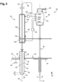
- Such a preform 22 is shown in figure 2 . It is made of thermoplastic material, here polyethylene terephthalate (PET). It is conventionally obtained by injection molding. It has a substantially axisymmetric shape around a main “Z0” axis of vertical orientation.
- PET polyethylene terephthalate
- FIG 2 it has a cylindrical body 24 with a tubular wall closed at its lower end by a bottom 26, and which is extended at its upper end by a neck 28 open vertically upwards, also tubular.
- An internal face 29 of the wall delimits the interior of the preform 22.
- the neck 28 is generally injected so as to already have its final shape while the body 24 of the preform 22 is intended to undergo a relatively significant deformation to form the final container during a subsequent forming step.
- the neck 28 of the preform 22 also includes an annular collar 30 which projects radially.
- the collar 30 is here arranged at the junction between the base of the neck 28 and the body 24.
- the processing device 20 comprises a carousel 32 rotatably mounted around a central vertical axis "Z1" on a fixed base 34.
- the base 34 is fixed relative to the ground on which the treatment device 20 rests.
- the carousel 32 is more particularly driven in continuous rotation, here in a counterclockwise direction as indicated by the arrow F of the figure 1 , by a vertical shaft 36 with a central “Z1” axis, for example by means of an electric motor not shown.
- the carousel 32 carries members 38 for holding the preforms 22 in order to drive the preforms 22 in line along a common arcuate trajectory centered on the central axis "Z1".
- the holding members 38 are here formed by notches in the shape of a semi-circle made on the outer periphery of a crown 40.
- the crown 40 is fixedly mounted on the carousel 32.
- Each holding member 38 makes it possible to accommodate the part of the body 24 of the preform 22 located just below the collar 30, while the collar 30 rests on an upper face of the crown 40 thus making it possible to drive the preform 22 along its trajectory.
- the holding members are formed by clamps which grip each preform just above or just below their collar.
- an arcuate rail 42 fixed relative to the base 34, is arranged along the arcuate trajectory of the preforms 22.
- the preforms 22 thus slide along the rail 42 which allows it to be retained radially inside their associated holding members 38.
- the crown 40 comprises for example thirty-two or forty holding members 38 distributed regularly around its periphery.
- the processing device 20 is designed to allow a large flow rate of preforms 22 to be transported and dedusted, for example of the order of 60,000 preforms per hour.
- the preforms 22 are conveyed to an entrance 44 of the processing device 20 by an entry wheel 46 represented schematically by a circle at the figure 1 .
- the preforms 22 are transferred, after treatment, here after dust removal, to an output wheel 48 shown schematically by a circle at the figure 1 , at an outlet 50.
- the entry and exit wheels 46, 48 are for example notched wheels having holding members 38 similar to those described for the carousel 32.
- the trajectory of the preforms 22 extends here over an angular sector greater than 180°, for example of the order of 300°.
- the carousel 32 is also equipped with several processing stations 52 which make it possible to treat, here to remove dust, the preforms 22 during their transport from the entrance 44 to the outlet 50.
- Each processing station 52 is on board the carousel 32, that is to say that each processing station 52 is driven in rotation around the central axis "Z1" integrally with the carousel 32.
- each treatment station 52 comprises at least one insufflation tube 54 which is carried on the carousel 32.
- Each insufflation tube 54 is arranged vertically in correspondence with an associated holding member 38.
- the carousel 32 includes as many insufflation tubes 54 as holding members 38.
- Each insufflation tube 54 has a free lower end which is provided with an insufflation nozzle 55 and an upper end provided with a supply orifice 58 which is intended to be connected to a source (not shown) of gas pressure treatment, as will be explained in more detail later.
- a dust removal treatment the treatment gas is for example formed by air.
- the pressure of the dust removal gas is for example of the order of 7 bars.
- the treatment gas is formed by a sterilizing gas.
- a sterilizing gas is for example a gas comprising a powerful oxidizing agent such as hydrogen peroxide and/or peracetic acid.
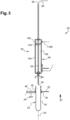
- Each insufflation tube 54 is mounted sliding vertically on the carousel 32 between an extreme position retracted vertically upwards, as shown in Figure 3 , and a lower inserted extreme position as shown in figure 2 .
- a vertical rectilinear lower end section of the insufflation tube 54 is intended to be inserted inside a preform 22 carried by the holding member 38 associated by its neck 28.
- the tube 54 insufflation is here coaxial with the main axis "Z0" of said preform 22.
- the insufflation nozzle 55 is arranged at a short distance "d" from the bottom 26 of the preform 22.
- the insufflation tube 54 is entirely extracted from the preform 22 carried by the associated holding member 38 to allow the transfer of a preform 22 dusted towards the exit wheel 48 radially outwards and the reception of a new preform 22 coming from the input wheel 46 radially towards the inside of the holding member 38.
- each insufflation tube 54 is controlled by at least one actuator which is automatically controlled as a function of the angular position of the carousel 32.
- each treatment station 52 comprises a single actuator which allows to simultaneously control the sliding of all the insufflation tubes 54 of said treatment station 52.
- Such an actuator is for example formed by an electric motor controlled by a rotating collector or by any other known and suitable motorization means.
- the actuator is formed by a pneumatic cylinder 56 which will be described in more detail later.
- each insufflation tube 54 travels a circular trajectory divided from upstream to downstream into several fixed angular sectors relative to the base 34 which have been represented in the figure 1 .
- the operation of the treatment device 20 in normal mode is described for an insufflation tube 54, the description being applicable to each of the insufflation tubes 54.
- each preform 22 is received in one of the members 38 for holding the inlet 44 while the tube 54 associated insufflation remains in its upper retracted position.
- the carousel 32 continues its rotation, bringing the insufflation tube 54 to a second angular sector, subsequently called “S1" angular insertion sector, along which the insufflation tube 54 moves from its extreme position retracted to its extreme inserted position.
- This angular insertion sector “S1" extends for example over approximately 25°.
- the insufflation tube 54 When the insufflation tube 54 reaches its extreme inserted position, it enters a third angular sector of its trajectory, subsequently called inserted angular sector "S2", along which each insufflation tube 54 remains in its extreme inserted position .
- the insufflation nozzle 55 emits a continuous jet of pressurized treatment gas which expels the dust contained in the preform 22 to the outside by going up along the internal face 29 of the preform 22 to the neck 28.
- the dust driven outside the preform 22 are then collected by a dust vacuum cleaner (not shown) to avoid polluting the other preforms 22.
- the inserted angular sector "S2" extends for example over approximately 120°.
- the insufflation tube 54 When the insufflation tube 54 reaches its extreme retracted position, it returns to the retracted angular sector "S0" of its trajectory. The insufflation tube 54 reaches its extreme retracted position before the preform 22 reaches the outlet 50 in order to allow the transfer of the preform 22 thus dusted towards the outlet wheel 48.
- the process gas source is fixed relative to the ground.
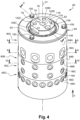
- the treatment device 20 comprises a rotating fluid distributor 60 comprising at least one first treatment stage 60A.
- such a rotating fluid distributor 60 comprises an internal stator 62.
- the stator 62 is mounted fixed relative to the base 34, for example by means of flats 63 cooperating with an anti-rotation device (not shown) to block its rotation relative to the base 34.
- the stator 62 has a generally cylindrical shape coaxial with the central “Z1” axis.
- the external rotor 64 has the shape of a vertical axis sleeve.
- the rotor 64 is rotatably mounted around the stator 62 coaxially with the central axis "Z1".
- the rotor 64 is integral in rotation with the carousel 32.
- bearings 65 for guiding the rotation of the rotor 64 are interposed radially between the rotor 64 and the stator 62.
- the rotating fluid distributor 60 here comprises two guide bearings 65 which are arranged at each of its vertical ends.
- rolling bearings 65 are rolling bearings 65. In a variant not shown of the invention, these are plain bearings.
- the rotor 64 comprises at least one processing port 66A passing through it radially.
- the treatment lumen 66A is connected to at least one insufflation tube 54 via a flexible pipe 68 shown in figure 2 And 3 .
- the processing light 66A thus travels a circular path around the central axis “Z1”.
- Each treatment light 66A is here connected to a treatment station 52.
- Each treatment station 52 here comprises four insufflation tubes 54.
- THE treatment device 20 shown in figure 1 thus comprises forty insufflation tubes 54 which are carried in groups of four by each of ten treatment stations 52.
- the rotor 64 thus comprises ten processing lights 66A which are arranged at the same level and which are regularly distributed around the same section of the rotor 64.
- the ten processing lights 66A are more particularly identical so that the rotor section 64 container has rotational symmetry around the central “Z1” axis.
- This configuration advantageously makes it possible to limit the number of treatment lights 66A produced in the rotor 64, while making it possible to control the distribution of treatment gas by sector as will be explained subsequently.
- each treatment light can supply another number of insufflation tubes, for example one, two, three or more.
- a treatment gas distribution chamber 70A is interposed radially between the stator 62 and the rotor 64 at the level of the treatment port 66A.
- the processing light 66A is capable of opening into the distribution chamber 70A through an internal opening 71A on at least a first angular sector of its circular trajectory, called "active angular sector 72-ON”.
- the distribution chamber 70A extends over a vertical height "H" which is substantially equal to or slightly greater than the height of the internal opening 71A of the treatment lumen 66A.
- the internal opening 71A of the processing lumen 66A has a circular section.
- the height "H" of the distribution chamber 70A is here slightly greater than the diameter of the internal opening 71A.
- the sealing of the distribution chamber 70A is ensured vertically in both directions by two spacer rings 84 which are interposed radially between the rotor 64 and the stator 62.
- the intermediate rings 84 are here mounted fixed with respect to the stator 62 and sliding with respect to the rotor 64.
- Each spacer ring 84 is here made of a metallic material.
- An annular inner seal 85A made of elastomeric material is inserted radially between the stator 62 and the intermediate ring 84, on the one hand, and an outer annular seal 85B is inserted radially between the rotor 64 and the intermediate ring 84 , on the other hand.
- the outer sealing gasket 85B rests radially sliding on the outer cylindrical face of the intermediate ring 84.
- the internal and external cylindrical faces of the intermediate ring 84 have a sufficiently smooth surface condition to vertically guarantee the sealing of the distribution chamber 70A.
- the first processing stage 60A thus includes the processing lights 66A and the distribution chamber 70A.
- the stator 62 includes a treatment gas supply pipe 74 which supplies the treatment gas distribution chamber 70A.
- the treatment gas supply pipe 74 more particularly connects at least one upstream orifice 76 formed in an axial end face 78, here upper, of the stator 62 to at least one downstream orifice 80 which opens into the distribution chamber 70A .
- the downstream orifice 80 opens here radially outwards at the same level as the treatment ports 66A.
- the stator 62 here has a single upstream orifice 76 and a single downstream orifice 80.
- the treatment gas supply pipe 74 is here formed of a single elbow pipe which comprises a generally vertical section which is connected to the upstream orifice 76, and a radial section which is connected to the downstream orifice 80.
- the circular trajectory of the processing light 66A is here divided into two complementary angular sectors comprising a single active angular sector 72-ON and a single inactive angular sector 72-OFF.
- the active angular sector 72-ON coincides at least with the entire inserted angular sector "S2".
- the inactive angular sector 72-OFF of the rotating fluidic distributor 60 coincides at least with the angular insertion sector S1. This makes it possible in particular to avoid the overpressure plug effect mentioned in the preamble to the description. Consequently, it is possible to align the insufflation tube 54 with the axis "Z0" of the preform 22 and thus reduce the distance "d" to a minimum.
- the active angular sector 72-ON extends over the entire inserted angular sector "S2" and over at least part of the retraction angular sector “S3", while the sector 72-OFF inactive angular extends over the complementary part of the retracting angular sector "S3", over the retracted angular sector "S0" and over the angular insertion sector "S1".
- the active angular sector 72-ON extends for example over approximately 145°, from the start of the inserted angular sector "S2”, while the inactive angular sector 72-OFF extends over the complementary part of the trajectory , or approximately 215°.
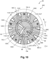
- the stator 62 includes a fixed shutter face 82A which closes each treatment light 66A on the inactive angular sector 72-OFF of their circular trajectory, as shown in figure 5 .
- the shutter face 82A has the shape of a cylindrical segment which extends circumferentially over said inactive angular sector 72-OFF around the central axis "Z1" of the stator 62, while the distribution chamber 70A extends over the active angular sector 72-ON.
- a functional radial clearance is reserved between the shutter face 82A and the rotor 64 to allow rotation of the rotor 64 without friction. However, this clearance is sufficiently low so that the flow of treatment gas likely to reach the treatment ports 66A closed by the shutter face 82A is negligible.
- the stator 62 is made of several distinct elements.
- the stator 62 thus comprises a core 86 which is equipped with the treatment gas supply pipe 74.
- the core 86 has a cylindrical shape and is arranged in the center of the stator 62.
- the stator 62 further comprises an element attached and fixed to the core 86 which includes the shutter face 82A.
- the added element is here formed by a first ring, called the processing ring 88A, which is interposed radially between the core 86 of the stator 62 and the rotor 64.
- the treatment ring 88A is delimited vertically by a planar annular upper face and by a planar annular lower face and it is delimited radially by an internal cylindrical face 90A and by an external cylindrical face 92A.
- the treatment ring 88A is received in an adjusted manner around the core 86.
- the treatment ring 88A is not received tight around the core 86, but with a radial clearance allowing its vertical sliding to allow its assembly and disassembly of easy way.
- the distribution chamber 70A is here delimited radially between a segment of the external face of the treatment ring 88A and the rotor 64.
- the external face 92A comprises, on said segment, a concave housing 94A.
- the rest of the external face 92A has a smooth cylindrical surface forming the face 82A shutter.
- the concave housing 94A is for example delimited vertically by two edges 96.
- the concave housing extends over the entire height of the treatment ring.
- the treatment ring 88A is intended to be fixed around the core 86 at the level of the treatment ports 66A and at the level of the downstream orifice 80 of the treatment gas supply pipe 74.
- the treatment ring 88A is crossed radially by a conduit 98 which allows the downstream orifice 80 to communicate with the interior of the distribution chamber 70A.
- the conduit 98 is here arranged in the middle of the housing in the circumferential direction.
- the processing ring 88A is interchangeably mounted on the core 86 so that the extent of the inactive angular sector 72-OFF can be adjusted by replacing the current processing ring 88A with a replacement processing ring 88A having a face 82A d 'obturation extending over a different angular sector.
- the treatment ring 88A is for example fixed to the core 86 via radial fixing screws 100, here two in number, as shown in Figure Figure 6 .
- the treatment ring is for example secured in rotation with the core by vertical interlocking means of complementary shape such as a flat or grooves.
- the treatment ring is then immobilized vertically by means of spacer rings which are themselves fixed to the core, for example by elastic washers of the "circlip" type.
- the treatment ring 88A is here made of a rigid plastic material.
- the treatment ring 88A is for example produced by molding.
- the treatment ring 88A is made of a metallic material.
- the actuators are here formed by pneumatic cylinders 56.
- each pneumatic cylinder 56 is controlled automatically as a function of the angular position of the carousel 32.
- the pneumatic cylinder 56 comprises a piston 102 which controls the rise and fall of the associated inflation tube(s) 54.
- the pneumatic cylinder 56 also comprises a cylinder 104 in which the piston 102 is mounted sliding vertically between a first upper extreme position corresponding to the retracted extreme position of the associated insufflation tubes 54, as shown in Fig. Figure 3 , and a lower extreme position corresponding to the inserted extreme position of the associated insufflation tubes 54, as shown in figure 2 .
- a first working chamber 106 for controlling the pneumatic cylinder 56 in a first of its extreme positions is delimited between the piston 102 and one of the vertical ends of the cylinder 104.
- the first working chamber 106 here controls the rise of the tube 54 of inflation towards its extreme retracted position.
- the pneumatic cylinder 56 also comprises a second working chamber 108 for controlling the pneumatic cylinder 56 in a second of its extreme positions which is delimited between the piston 102 and the other of the vertical ends of the cylinder 104.
- the second working chamber 108 here controls the descent of the insufflation tube 54 towards its extreme inserted position.
- the pneumatic cylinder is a single-acting cylinder.
- the pneumatic cylinder has only one working chamber to control the sliding of the piston in one of its extreme positions, the piston being controlled in the other of its extreme positions by an elastic return member such as a spring.
- the pneumatic cylinder 56 is controlled by means of the rotating fluid distributor 60.
- the rotating fluid distributor 60 comprises an additional stage, called the control stage 60B, 60C, associated with each of the working chambers 106, 108 of the pneumatic cylinder 56.
- the processing stage 60A is here arranged at the upper end of the rotating fluid distributor 60.
- the rotor 64 comprises at least one first actuation light 66B which is connected to the associated working chamber of the pneumatic cylinder 56, here the second chamber 108, via a pipe 110B.
- the actuation light 66B thus travels a circular path around the central axis “Z1”.
- the first control stage 60B is associated with the second working chamber 108 to control the insufflation tubes 54 towards their extreme inserted position.
- Each processing station 52 includes a pneumatic cylinder 56.
- the first stage 60B for controlling the rotor 64 thus comprises ten actuation lights 66B which are arranged at the same level and which are regularly distributed around the same section of the rotor 64.
- the ten actuation lights 66B are more particularly identical in so that the rotor section 64 containing them has rotational symmetry around the central axis “Z1”.
- Each actuation light 66B is here aligned vertically on the same line with the processing light 66A associated with the same processing station 52.
- the first control stage 60B comprises a pressure chamber 70B-1 which is interposed radially between the stator 62 and the rotor 64 at the level of the actuation lights 66B.
- the actuation light 66B is capable of opening through an internal opening 71B in the pressure chamber 70B-1 on a first angular sector of its circular trajectory, called "actuation angular sector 112B-IN”.
- the first control stage 60B also includes an exhaust chamber 70B-2 which is interposed radially between the stator 62 and the rotor 64 at the level of the actuation port 66B.
- the actuation light 66B is capable of opening through its internal opening 71B into the exhaust chamber 70B-2 onto a second angular sector of its circular trajectory, called "exhaust angular sector 112B-OUT".
- the angular actuation sector 112B-IN and the angular exhaust sector 112B-OUT are two distinct angular sectors which do not overlap.
- Radial separation partitions 114B are provided to isolate the pressure chamber 70B-1 from the exhaust chamber 70B-2.
- the pressure and exhaust chambers 70B-1, 70B-2 extend over a common vertical height "H" which is substantially equal to or slightly greater than the height of the internal opening 71B of the actuation port 66B.
- the internal opening 71B of the actuation light 66B has a circular section.
- the height of the pressure and exhaust chambers 70B-1, 70B-2 is here slightly greater than the diameter of the internal opening.
- the sealing of the pressure and exhaust chambers 70B-1, 70B-2 is ensured vertically in both directions in the same way as the sealing of the distribution chamber 70A, that is to say by two circular intermediate rings 84 which are interposed radially between the rotor 64 and the stator 62.
- An internal seal 85A of seals made of elastomeric material is interposed radially between the stator 62 and the intermediate ring 84, d on the one hand, and an external seal 85B is inserted radially between the rotor 64 and the intermediate ring 84, on the other hand.
- the stator 62 and more particularly the core 86 of the stator 62, includes a pressure pipe 116 which supplies the pressure chamber 70B-1 with compressed working gas.
- the pressure pipe 116 more particularly connects at least one upstream orifice 118 formed in the end face 78, here upper, of the stator 62 to at least one downstream orifice 120B for supplying the pressure chamber 70B-1.
- the downstream orifice 120B opens here radially outwards at the same level as the actuation ports 66B.
- the stator 62 here comprises a single upstream orifice 118 and a single downstream orifice 120B for supplying the pressure chamber 70B-1.
- the pressure pipe 116 is here formed of a single bent pipe which comprises a generally vertical section which is connected to the upstream orifice 118, and a radial section which is connected to the downstream orifice 120B.
- the core 86 of the stator 62 further comprises an exhaust pipe 122B which makes it possible to evacuate the working gas under pressure contained in the exhaust chamber 70B-2.
- the exhaust pipe 122B more particularly connects at least one upstream orifice 124B which opens into the exhaust chamber 70B-2 at least to at least one downstream orifice 126B formed in an end face 78, here upper, of the stator 62
- the upstream orifice 124B opens here radially outwards at the same level as the actuation ports 66B.
- the stator 62 here has a single upstream orifice 124B and a single downstream orifice 126B.
- the exhaust pipe 122B is here formed of a single bent pipe which includes a section generally radial which is connected to the upstream orifice 124B, and a vertical section which is connected to the downstream orifice 126B.
- the gas escaping through the exhaust line 122B although having a pressure lower than the pressure of the working gas entering through the supply line, always has a pressure higher than atmospheric pressure.
- the first stage 60B for controlling the stator 62 comprises two fixed shutter faces 82B-1, 82B-2 which close each actuation light 66B on intermediate angular sectors 112B-OFF1, 112B-OFF2 of their circular trajectory.
- the first intermediate angular sector 112B-OFF1 is inserted circumferentially between the angular actuation sector 112B-IN and the angular exhaust sector 112B-OUT according to the direction of rotation of the rotor 64 indicated by the arrow "F" of the figure 8 .
- the second intermediate angular sector 112B-OFF2 is inserted circumferentially between the angular exhaust sector 112B-OUT and the angular actuation sector 112B-IN according to the direction of rotation of the rotor 64 indicated by the arrow "F" of the figure 8 .
- each shutter face 82B-1, 82B-2 has the shape of a cylindrical segment which extends circumferentially on said intermediate angular sector around the central axis "Z1" of the stator 62.
- the first shutter face 82B-1 which corresponds to the intermediate angular sector 112B-OFF1 located just before the angular retraction sector "S3" extends over an angle much smaller than the second face 82B- 2 shutter, which corresponds to the intermediate angular sector 112B-OFF2 which is located just before the angular sector "S1" of insertion.
- the first intermediate angular sector 112B-OFF1 extends over 20° while the second intermediate angular sector 112B-OFF2 extends over 60°.
- a functional radial clearance is reserved between each shutter face 82B-1, 82B-2 and the rotor 64 to allow rotation of the rotor 64 without friction. However, this clearance is sufficiently low so that the flow of working gas likely to reach the actuation ports 66B closed by the shutter faces 82B-1, 82B-2 is negligible.
- the stator 62 further comprises an element attached and fixed to the core 86 which includes the shutter faces 82B-1, 82B-2 and the separation partitions 114B.
- the added element is here formed by a ring, called the first control ring 88B, which is interposed radially between the core 86 of the stator 62 and the rotor 64.
- the first control ring 88B is delimited vertically by a flat annular upper face and by a plane annular lower face and it is delimited radially by an internal cylindrical face 90B and by an external cylindrical face 92B.
- the first pilot ring 88B is received in a fitted manner around the core 86.
- the first pilot ring 88B is not received tight around the core 86, but it is received with a radial clearance allowing its vertical sliding to allow its easy assembly and disassembly.
- One of the two chambers 70B-1 is here delimited radially between a segment of the external face 92B of the first control ring 88B and the rotor 64.
- the external face 92B comprises, on said segment, a concave 94B-1 housing.
- the rest of the external face 92B has a smooth cylindrical surface.
- the concave housing 94B-1 is for example delimited vertically by two edges 96.
- the concave housing extends over the entire height of the first control ring.
- the pressure inside the two chambers 70B-1, 70B-2 is intended to be very different.
- the pressure in the pressure chamber 70B-1 is intended to be much higher than that of the exhaust chamber 70B-2.
- the working gas would be likely to pass through the functional clearance reserved between at least one of the shutter faces 82B-1, 82B-2 and the rotor 64, for example through the functional clearance delimited between the first shutter face 82B-1 and the rotor 64 which extends over an intermediate angular sector 112B-OFF1 shorter than the second intermediate angular sector 112B-OFF2 .
- a significant portion of the working gas arriving via pressure pipe 116 would thus leave directly via exhaust pipe 122B. To avoid such a leak, it is proposed to reduce the passage section between the two chambers 70B-1, 70B-2 through the functional clearance.
- the other of the two chambers 70B-2 is delimited radially between a second internal cylindrical face segment 90B of the first ring 88B and the core 86.
- the internal face comprises, on said segment, a concave 94B-2 housing. Said housing 94B-2 extends here over the entire height of the first control ring 88B.
- the internal chamber 70B-2 here forms the exhaust chamber 70B-2, while the external chamber 70B-1 forms the pressure chamber 70B-1.
- the external cylindrical face segment 92B is equipped with a plurality of through orifices 128B distributed over its length at 66B actuation light level.
- the passage section between the two chambers 70B-1, 70B-2 is reduced to the sum of the sections of the through orifices 128.
- There dimension and quantity of the through orifices, however, remains sufficient to allow the exhaust of the working gas contained in the associated working chamber 106, 108 in the direction of the exhaust chamber 70B-2 on the angular exhaust sector.
- the internal chamber 70B-2 is separated circumferentially from the external chamber 70B-1 by the radial separation partitions 114B which each carry one of the shutter faces 82B-1, 82B-2.
- the internal chamber forms the pressure chamber
- the external chamber forms the exhaust chamber
- the first control ring 88B is intended to be fixed around the core 86 at the level of the actuation ports 66B and at the level of the orifice 120B downstream of the pressure pipe 116 and the orifice 124B upstream of the pipe 122B d 'exhaust.
- the first control ring 88B is crossed radially by a conduit 130B which allows the downstream orifice 120B of the pressure pipe 116 to communicate with the interior of the pressure chamber 70B-1.
- the conduit 130B is here arranged in the middle of the housing in the circumferential direction.
- the upstream orifice 124B of the exhaust pipe 122B opens directly into the housing delimiting the exhaust chamber 70B-2.
- the first control ring 88B is mounted interchangeably on the core 86 so as to be able to adjust the extent of the angular sectors 112B-IN, 112B-OFF1, 112B-OUT, 112B-OFF2 by replacing the current first control ring 88B by a replacement pilot ring having pressure and exhaust chambers 70B-1, 70B-2 extending over different angular sectors.
- the first control ring 88B is for example fixed to the core 86 via a fixing screw 132.
- the first control ring is for example secured in rotation with the core by vertical interlocking means of complementary shape such as a flat or grooves.
- the first control ring is then immobilized vertically by means of the spacer rings.
- the first control ring 88B is here made of a rigid plastic material.
- the first control ring 88B is for example made by molding.
- the pilot ring is made of a metallic material.
- the rotating fluidic distributor 60 comprises a second control stage 60C which is almost identical to the first control stage 60B.
- the second control stage 60C thus includes actuation lights 66C identical to those of the first control stage 60B, but they are connected to the first working chamber 106 of the associated pneumatic cylinder 56.
- the second pilot stage 60C differs from the first in that the position of the pressure and exhaust chambers 70C-1, 70C-2 are modified so that the pressure chamber 70B-1 of the first pilot stage 60B is in coincidence with the exhaust chamber 70C-2 of the second pilot stage 60C, while the exhaust chamber 70B-2 of the first pilot stage 60B is in coincidence with the pressure chamber 70C-1 of the second pilot stage 60C .
- the angular sector 112C-IN of actuation of the second control stage 60C coincides with the angular exhaust sector 112B-OUT of the first control stage 60B
- the angular sector 112C-OUT of exhaust of the second stage 60C control coincides with the angular sector 112B-IN of actuation of the first control stage 60B.
- the second control stage 60C is here arranged vertically below the first control stage 60B.
- the pressure chamber 70C-1 of the second control stage 60C is here supplied by the same pressure pipe 116.
- the generally vertical section of the bent pipe forming the pressure pipe 116 is common to the two control stages 60B, 60C and it supplies a second radial section which is connected to two downstream orifices 120C which supply the pressure chamber 70C-1 of the second pilot stage 60C.
- the second control stage 60C comprises an exhaust pipe 122C distinct from the exhaust pipe 122B associated with the first control stage 60B.
- the two exhaust pipes 122B, 122C do not communicate with each other inside the core 86.
- the second control stage 60C also includes a control ring 88C similar to that of the first control stage 60B.
- the control ring 88C of the second control stage 60C is identical to the control ring 88B which is shown in the Figure 9 by turning the ring over, that is to say by reversing the direction of the arrow "V".
- the treatment device 20 is capable of operating in a secure mode in which all the actuators are controlled quickly and simultaneously in their extreme retracted position in the event of a malfunction of the treatment device 20 in order to prevent the tubes from 54 of insufflation do not collide with other elements, such as preforms 22.
- the rotating fluid distributor 60 comprises a fourth stage 60D of security.
- This safety stage 60D functions as a rotating connector which simultaneously supplies all the pneumatic cylinders 56 with working gas to control them towards their extreme retracted position.
- the safety stage 60D is here arranged at the lower end of the rotating fluidic distributor 60.
- the rotor 64 has as many safety lights 66D passing through it radially as the treatment device 20 has pneumatic cylinders 56. Each safety light 66D is connected to the first associated working chamber 106. Each 66D safety light thus travels a circular path around the central “Z1” axis.
- the connection to the first working chamber 106 is made via a circuit selector 133 which allows the first working chamber 106 to be connected alternately to the safety light 66D or to the second stage actuation light 66C 60C associated piloting.
- the rotor 64 thus comprises ten safety lights 66D which are arranged at the same level and which are regularly distributed around the same section of the rotor 64.
- the ten safety lights 66D are more particularly identical so that the rotor section 64 container has rotational symmetry around the central “Z1” axis.
- Each safety light 66D is here aligned vertically on the same line with the processing light 66A associated with the same processing station 52.
- a safety chamber 70D is interposed radially between the stator 62 and the rotor 64 at the level of the safety lights 66D.
- the 70D safety chamber has an annular shape which goes all the way around the stator 62.
- each safety light 66D opens through an internal opening 71D permanently into the safety chamber 70D over its entire circular trajectory.
- the safety chamber 70D is here delimited radially directly by the core 86 towards the inside and directly by the rotor 64 towards the outside.
- the safety chamber 70D extends over a vertical height which is substantially equal to or slightly greater than the height of the internal opening 71D of the safety light 66D.
- the internal opening 71D of the safety light 66D has a circular section.
- the height of the safety chamber 70D is here slightly greater than the diameter of the internal opening 71D.
- the core 86 of the stator 62 includes a safety pipe 134 for supplying working gas to the working gas safety chamber 70D.
- the safety pipe 134 more particularly connects at least one upstream orifice 136 formed in an end face 78, here upper, of the stator 62 to at least one downstream orifice 138 which opens into the safety chamber 70D.
- the stator 62 here has a single upstream orifice 136 and a single downstream orifice 138.
- the safety pipe 134 is here formed of a single bent pipe which comprises a generally vertical section which is connected to the upstream orifice 136, and a radial section which is connected to the downstream orifice 138.
- the safety pipe 134 is here independent of the pressure pipe 116, that is to say that the two pipes 116, 134 do not communicate with each other.
- This safety pipe 134 is supplied with working gas in a controlled manner by means of an upstream distributor 140 which alternately supplies the pressure pipe 116 or the safety pipe 134.
- the distributor 140 is arranged upstream of the rotating fluid distributor 60.
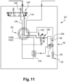
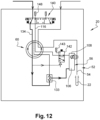
- This 140 upstream distributor has three positions here. In a first position normal, shown at Figure 11 and corresponding to the normal mode, it supplies the pressure pipe 116, while the safety pipe 134 is closed. In a safe position, shown in Figure 12 and corresponding to the secure mode, it supplies the safety pipe 134 with working gas, while the safety pipe 116 is closed. In a neutral position (not shown), corresponding to the complete shutdown of the treatment device 20, neither of the two pipes is supplied with working gas.
- the safety pipe 134 and the pressure pipe 116 are here connected to the same source of working gas via the upstream distributor 140.
- the source of process gas is here distinct from the source of working gas.
- the working gas source is here fixed relative to the ground.
- the working gas contained in the second working chamber 108 of the pneumatic cylinder 56 must be able to be evacuated through an exhaust 143 permanently.
- the second working chamber 108 is connected to a downstream distributor 142, here of the spool distributor type, which is controlled between a normal operating position, illustrated in Figure 11 , and a safety position, illustrated in Figure 12 .
- the downstream distributor 142 is therefore on board the carousel 32.
- the downstream distributor 142 makes it possible to alternately connect the second working chamber 108 either to the associated actuation light 66B in normal mode, or to an exhaust 143 on board the carousel 32 in Safe mode.
- the drawer of the downstream distributor 142 is here elastically returned to its normal operating position.
- the drawer of the downstream distributor 142 is actuated by the working gas by means of a pipe connecting the safety chamber 70D to the downstream distributor 142, for example by means of a actuator (not shown) such as a piston or a electrical coil.
- the working gas thus pushes the drawer towards its safe operating position against the elastic return force.
- the rotor 64 comprises trigger orifices 144 which are arranged at the same level as the safety lights 66D and alternating with them around the safety stage 60D of the rotor 64.
- Each trigger orifice 144 is connected to the cylinder of an associated downstream distributor 142.
- the upstream distributor 140 occupies its normal position.
- the safety chamber 70D is then connected to an exhaust 146 located upstream of the upstream distributor 140, while the pressure chambers 70B-1 and 70C-1 of the control stages 60B, 60C are supplied with compressed working gas.
- the circuit selector 133 is controlled to connect the first working chamber 106 of the pneumatic cylinder 56 to the actuation light 66C of the second associated control stage 60C.
- the downstream distributor 142 occupies its normal position in which the second working chamber 108 of the pneumatic cylinder 56 is connected to the actuation port 66B of the first associated control stage 60B.
- the upstream distributor 140 occupies its safety position.
- the safety chamber 70D is then supplied with compressed working gas, while the pressure chambers 70B-1 and 70C-1 of the control stages 60B, 60C are connected to an exhaust 148 located upstream of the upstream distributor 140.
- the circuit selector 133 is controlled to connect the first working chamber 106 of the pneumatic cylinder 56 to the safety light 66D of the safety stage 60D.
- the downstream distributor 142 occupies its safety position in which the second working chamber 108 of the pneumatic cylinder 56 is connected to the exhaust 143.
- the treatment ring 88A and the control rings 88B, 88C are inserted vertically around the core 86 and stacked with vertical interposition of the intermediate rings 85.
- This stack here rests upwards against a shoulder of the core with the interposition of another ring 85 between the treatment ring 88A and the shoulder. This stack is then held in place by an elastic ring.
- the chamber 70D is formed by means of a final spacer ring which is slipped around the core and fixed at a vertical distance from the spacer ring 85 at the lower end of the stack.
- the treatment ring 88A and the rings 88B, 88C are then secured in rotation with the core 86 by their respective screws 100, 132.
- the rotor 64 is then slipped around the stator 62 thus formed with the interposition of rolling bearings 65.
- the rotor 64 comprises is produced in several attached sleeves each corresponding to a section of the rotor 64.
- a first sleeve 64A of rotor 64 comprising all the processing ports 66A is used to produce the processing stage 60A.
- a single sleeve 64B of rotor 64 comprising all the actuation lights 66B and 66C is here common to the two control stages 60B, 60C.
- a final sleeve 64D of rotor 64 comprising all the safety lights 66D and the triggering orifices 144 is used to produce the safety stage 60D. All the sleeves 64A, 64B, 64D of rotor 64 are here stacked and held vertically tight together by at least one vertical lag screw 150.
- the invention thus makes it possible to use the treatment gas only on the useful sections of the trajectory of the insufflation tubes 54.
- the distribution of the treatment gas is carried out in a simple manner by a rotating fluid distributor 60.
Landscapes
- Engineering & Computer Science (AREA)
- Manufacturing & Machinery (AREA)
- Mechanical Engineering (AREA)
- Blow-Moulding Or Thermoforming Of Plastics Or The Like (AREA)
- Processing And Handling Of Plastics And Other Materials For Molding In General (AREA)
Claims (11)
- Drehender Fluidverteiler (60) für eine Vorrichtung (20) zur Bearbeitung des Inneren von Vorformen (22) aus thermoplastischem Material durch Einblasen eines Bearbeitungsgases, der ein auf einen ortsfesten Sockel (34) um eine Mittelachse (Z1) rotierend montiertes Karussell (32) aufweist, wobei Halteorgane (38) der Vorformen (22) und Blasrohre (54) in das Karussell (32) integriert sind, die jedem Halteorgan (38) entsprechend in das Karussell (32) integriert sind, wobei der Verteiler aufweist:- einen internen Stator (62), der dazu bestimmt ist, bezüglich eines Sockels (34) ortsfest montiert zu werden, wobei der Stator (62) eine Versorgungsleitung (74) mit Bearbeitungsgas aufweist;- einen externen Rotor (64), der um eine Mittelachse (Z1) rotierend um den Stator (62) montiert ist und der mindestens eine den Rotor (64) radial durchquerende Bearbeitungsöffnung (66A) aufweist, die dazu bestimmt ist, an mindestens ein Rohr (54) zum Einblasen des Bearbeitungsgases in eine Vorform (22) angeschlossen zu werden, wobei die Bearbeitungsöffnung (66A) eine Kreisbahn um die Mittelachse (Z1) herum durchläuft;- eine zwischen den Stator (62) und den Rotor (64) eingefügte Verteilungskammer (70A), wobei die Verteilungskammer (70A) durch die Versorgungsleitung (74) mit Bearbeitungsgas versorgt wird, und die Bearbeitungsöffnung (66A) in die Verteilungskammer (70A) in mindestens einem ersten Winkelbereich ihrer Kreisbahn mündet, "aktiver Winkelbereich (72-ON)" genannt;dadurch gekennzeichnet, dass der Stator (62) eine ortsfeste Verschlussseite (82A) aufweist, die jede Bearbeitungsöffnung (66A) in einem zweiten Winkelbereich ihrer Kreisbahn verschließt, "inaktiver Winkelbereich (72-OFF)" genannt.
- Drehender Fluidverteiler (60) nach dem vorhergehenden Anspruch, dadurch gekennzeichnet, dass die Kreisbahn der Bearbeitungsöffnung (66A) in zwei Winkelbereiche aufgeteilt ist, die einen einzigen aktiven Winkelbereich (72-ON) und einen einzigen inaktiven Winkelbereich (72-OFF) enthalten.
- Drehender Fluidverteiler (60) nach einem der vorhergehenden Ansprüche, dadurch gekennzeichnet, dass der Stator (62) einen Kern (86), der mit der Versorgungsleitung (74) ausgestattet ist, und ein aufgestecktes und am Kern (86) befestigtes Element aufweist, das die Verschlussseite (82A) aufweist.
- Drehender Fluidverteiler (60) nach dem vorhergehenden Anspruch, dadurch gekennzeichnet, dass das aufgesteckte Element von einem Bearbeitungsring (88A) gebildet wird, der radial zwischen dem Kern (86) des Stators (62) und dem Rotor (64) eingefügt wird.
- Drehender Fluidverteiler (60) nach dem vorhergehenden Anspruch, dadurch gekennzeichnet, dass die Verteilungskammer (70A) radial zwischen einem Segment des Bearbeitungsrings (88A) und dem Rotor (64) begrenzt wird.
- Drehender Fluidverteiler (60) nach einem der vorhergehenden Ansprüche, dadurch gekennzeichnet, dass der Rotor (64) eine Vielzahl von Bearbeitungsöffnungen (66A) aufweist, die gleichmäßig um den Rotor (64) herum verteilt sind.
- Drehender Fluidverteiler (60) nach einem der vorhergehenden Ansprüche, dadurch gekennzeichnet, dass der Rotor (64) mindestens eine aufgesteckte Muffe (64A) aufweist, die alle Bearbeitungsöffnungen (66A) aufweist.
- Drehender Fluidverteiler (60) nach einem der Ansprüche 4 oder 5, dadurch gekennzeichnet, dass der Bearbeitungsring (88A) austauschbar ist, um die Ausdehnung des inaktiven Winkelbereichs (72-OFF) regeln zu können.
- Vorrichtung (20) zur Bearbeitung des Inneren von Vorformen (22) aus thermoplastischem Material durch Einblasen von Bearbeitungsgas, die aufweist:- ein auf einen ortsfesten Sockel (34) um eine Mittelachse (Z1) rotierend montiertes Karussell (32), wobei Halteorgane (38) der Vorformen (22) in das Karussell (32) integriert sind;- Einblasrohre (54), die entsprechend jedem Halteorgan (38) in das Karussell (32) integriert sind;dadurch gekennzeichnet, dass sie einen drehenden Fluidverteiler (60) aufweist, der nach einem der vorhergehenden Ansprüche hergestellt ist.
- Bearbeitungsvorrichtung (20) nach dem vorhergehenden Anspruch, dadurch gekennzeichnet, dass jedes Einblasrohr (54) zwischen einer eingezogenen Endstellung, in der es dazu bestimmt ist, ganz außerhalb einer vom zugeordneten Halteorgan (38) getragenen Vorform (22) zu sein, und einer eingeführten Endstellung gleitend auf das Karussell (32) montiert ist, in der es dazu bestimmt ist, ins Innere einer vom zugeordneten Halteorgan (38) getragenen Vorform (22) eingeführt zu sein, wobei die Vorrichtung (20) mindestens ein Stellglied (56) aufweist, das abhängig von der Winkelstellung des Karussells (32) automatisch gesteuert wird, wobei jedes Einblasrohr (54) eine Kreisbahn durchläuft, die von stromaufwärts nach stromabwärts aufgeteilt ist in:- einen ersten eingezogenen Winkelbereich (S0), entlang dessen jedes Einblasrohr (54) seine eingezogene Endstellung einnimmt;- einen zweiten Einführwinkelbereich (S1), entlang dessen jedes Einblasrohr (54) sich von seiner eingezogenen Endstellung bis zu seiner eingeführten Endstellung verschiebt;- einen dritten eingeführten Winkelbereich (S2), entlang dessen jedes Einblasrohr (54) seine eingeführte Endstellung einnimmt;- einen vierten Einziehwinkelbereich (S3), entlang dessen jedes Einblasrohr (54) sich von seiner eingeführten Endstellung bis zu seiner eingezogenen Endstellung verschiebt;wobei der aktive Winkelbereich (72-ON) des drehenden Fluidverteilers (60) mindestens mit dem dritten eingeführten Winkelbereich (S2) übereinstimmt.
- Vorrichtung (20) nach dem vorhergehenden Anspruch, dadurch gekennzeichnet, dass der inaktive Winkelbereich (72-OFF) des drehenden Fluidverteilers (60) mindestens mit dem zweiten Einführwinkelbereich (S1) übereinstimmt.
Applications Claiming Priority (2)
| Application Number | Priority Date | Filing Date | Title |
|---|---|---|---|
| FR2004273A FR3109745B1 (fr) | 2020-04-29 | 2020-04-29 | "Distributeur fluidique tournant et dispositif de traitement de l'intérieur d'une préforme équipé d'un tel distributeur fluidique" |
| PCT/EP2021/060481 WO2021219472A1 (fr) | 2020-04-29 | 2021-04-22 | Distributeur fluidique tournant et dispositif de traitement de l'interieur d'une preforme equipe d'un tel distributeur fluidique |
Publications (2)
| Publication Number | Publication Date |
|---|---|
| EP4143003A1 EP4143003A1 (de) | 2023-03-08 |
| EP4143003B1 true EP4143003B1 (de) | 2024-04-10 |
Family
ID=71894940
Family Applications (1)
| Application Number | Title | Priority Date | Filing Date |
|---|---|---|---|
| EP21720276.1A Active EP4143003B1 (de) | 2020-04-29 | 2021-04-22 | Rotierender fluidverteiler und vorrichtung zur innenbehandlung einer vorform mit solch einem rotierenden fluidverteiler |
Country Status (5)
| Country | Link |
|---|---|
| EP (1) | EP4143003B1 (de) |
| JP (2) | JP2023523463A (de) |
| CN (1) | CN115551690A (de) |
| FR (1) | FR3109745B1 (de) |
| WO (1) | WO2021219472A1 (de) |
Families Citing this family (1)
| Publication number | Priority date | Publication date | Assignee | Title |
|---|---|---|---|---|
| CN114789159B (zh) * | 2022-03-24 | 2023-07-28 | 蚌埠飞宇轴承有限公司 | 一种轴承加工用连续式清洗机 |
Family Cites Families (14)
| Publication number | Priority date | Publication date | Assignee | Title |
|---|---|---|---|---|
| FR2051980A6 (de) * | 1969-07-03 | 1971-04-09 | Oreal | |
| US4208852A (en) * | 1974-11-08 | 1980-06-24 | Pont-A-Mousson S.A. | Process for the aseptic packing of products and machine employing said process |
| JP3825517B2 (ja) * | 1996-12-17 | 2006-09-27 | 独立行政法人産業技術総合研究所 | 薄膜製造装置用噴霧ノズル弁 |
| DE10240852A1 (de) * | 2002-09-04 | 2004-03-18 | Linde Ag | Steuerventileinrichtung |
| FR2937889B1 (fr) * | 2008-11-04 | 2012-07-27 | Sidel Participations | Installation de nettoyage de recipients. |
| JP5358784B2 (ja) * | 2008-11-05 | 2013-12-04 | キリンテクノシステム株式会社 | ロータリバルブ装置 |
| EP2664829A1 (de) * | 2009-02-23 | 2013-11-20 | Josef K . Kihs | Ventilmechanismus zur Steuerung der Ausgabe eines unter Druck stehenden Fluids |
| FR3014352B1 (fr) * | 2013-12-09 | 2016-01-22 | Sidel Participations | Dispositif de traitement en serie de corps creux comportant une tige de traitement commandee en coulissement par un actionneur electrique et procede de traitement |
| EP3116702B1 (de) * | 2014-03-10 | 2018-07-04 | Discma AG | Verfahren zum formen und einstellen eines freiraums in einem behälter |
| BR112016024382A2 (pt) * | 2014-04-24 | 2017-08-15 | Onesubsea Ip Uk Ltd | dispositivo de controle de fluxo autorregulável |
| EP3040306A1 (de) * | 2014-12-29 | 2016-07-06 | Sidel Participations, S.A.S. | Verteiler für einen drehbaren Tank für eine Fülleinheit zum Befüllen von mehreren Artikeln mit einem fließfähigen Produkt |
| FR3054474B1 (fr) * | 2017-02-16 | 2018-08-17 | Sidel Participations | Dispositif et procede de depoussierage de l'interieur d'au moins une preforme |
| FR3068299B1 (fr) * | 2017-06-30 | 2019-08-16 | Poclain Hydraulics Industrie | Pivot de direction ameliore formant un conduit pneumatique interne |
| US10788135B2 (en) * | 2018-02-09 | 2020-09-29 | Nordson Corporation | Multi-port valve |
-
2020
- 2020-04-29 FR FR2004273A patent/FR3109745B1/fr active Active
-
2021
- 2021-04-22 CN CN202180031604.0A patent/CN115551690A/zh active Pending
- 2021-04-22 WO PCT/EP2021/060481 patent/WO2021219472A1/fr not_active Ceased
- 2021-04-22 JP JP2022566076A patent/JP2023523463A/ja active Pending
- 2021-04-22 EP EP21720276.1A patent/EP4143003B1/de active Active
-
2026
- 2026-02-09 JP JP2026019736A patent/JP2026071372A/ja active Pending
Also Published As
| Publication number | Publication date |
|---|---|
| FR3109745A1 (fr) | 2021-11-05 |
| CN115551690A (zh) | 2022-12-30 |
| JP2026071372A (ja) | 2026-04-28 |
| EP4143003A1 (de) | 2023-03-08 |
| WO2021219472A1 (fr) | 2021-11-04 |
| FR3109745B1 (fr) | 2022-05-13 |
| JP2023523463A (ja) | 2023-06-05 |
Similar Documents
| Publication | Publication Date | Title |
|---|---|---|
| EP3904045B1 (de) | Vorrichtung zum entstauben des inneren einer vorform | |
| EP2139666B1 (de) | Transfervorrichtung und lineares gerät zur herstellung von behältern | |
| EP2382144A1 (de) | Anlage zur herstellung von gefässen mit einem übertragungsrad mit verstellbarem schritt | |
| EP3363614B2 (de) | Vorrichtung und verfahren zum entstauben des inneren mindestens einer vorform | |
| EP1765574A1 (de) | Vorrichtung zum blasformen von thermoplastischen behältern | |
| FR2554801A1 (fr) | Appareil de bouchage | |
| CH690002A5 (fr) | Machine pour la fabrication de récipient en matière plastique. | |
| FR2901141A1 (fr) | Dispositif et procede de traitement, notamment de sterilisation d'objets | |
| WO2021219472A1 (fr) | Distributeur fluidique tournant et dispositif de traitement de l'interieur d'une preforme equipe d'un tel distributeur fluidique | |
| WO2021239936A1 (fr) | Installation de fabrication de recipients comportant une zone de transfert sterile | |
| EP3898176B1 (de) | Vorrichtung zum fördern von vorformen und verfahren zur steuerung solch einer vorrichtung zur winkelmässigen indexierung der vorformen in einer referenzposition | |
| FR2575406A1 (fr) | Machine pour la fabrication de bouteilles en matiere plastique avec mise en place de coupelles stabilisatrices et pressurisation interne au moyen d'un gaz | |
| EP1840034B1 (de) | Vorrichtung zum Einspritzen einer Flüssigkeit in sich in Bewegung befindlichen Behältern | |
| FR2639613A1 (fr) | Machine pour emballer des cigarettes dans des paquets durs a dessus basculant | |
| FR2639614A1 (fr) | Procede pour emballer des cigarettes dans des paquets durs a dessus basculant | |
| FR2801045A1 (fr) | Systeme de convoyage d'entites discretes comportant un dispositif de repartition et installation de soufflage de recipients munie d'un tel systeme | |
| EP1771593B1 (de) | Maschine zur behandlung von flaschen mit austauschbarer verbindungskartusche | |
| CH364212A (fr) | Machine à postes multiples pour la mise en conserve | |
| EP3424681B1 (de) | Vorrichtung zur behandlung von behältern, und entsprechende antriebsvorrichtung | |
| EP3393529B1 (de) | Verfahren zum sterilisieren der vorrichtung zum strecken einer behälterformvorrichtung und behälterfertigungsanlage | |
| EP1660371A1 (de) | Verfahren und anlage zum formen und füllen von thermoplastischen flaschen | |
| EP0508838B1 (de) | Druckmittelbetätigte Drehantriebsstellvorrichtung, insbesondere für Scheibenwischer | |
| EP4334109A1 (de) | Maschine zum reinigen von schalen durch blasen | |
| FR3008338A1 (fr) | "unite de moulage de recipients en matiere thermoplastique comportant des moyens de compensation" | |
| WO2012150247A1 (fr) | Dispositif commandé de robinetterie pour une installation de moulage de récipients par soufflage comportant des vannes actionnales individuellement |
Legal Events
| Date | Code | Title | Description |
|---|---|---|---|
| STAA | Information on the status of an ep patent application or granted ep patent |
Free format text: STATUS: UNKNOWN |
|
| STAA | Information on the status of an ep patent application or granted ep patent |
Free format text: STATUS: THE INTERNATIONAL PUBLICATION HAS BEEN MADE |
|
| PUAI | Public reference made under article 153(3) epc to a published international application that has entered the european phase |
Free format text: ORIGINAL CODE: 0009012 |
|
| STAA | Information on the status of an ep patent application or granted ep patent |
Free format text: STATUS: REQUEST FOR EXAMINATION WAS MADE |
|
| 17P | Request for examination filed |
Effective date: 20221020 |
|
| AK | Designated contracting states |
Kind code of ref document: A1 Designated state(s): AL AT BE BG CH CY CZ DE DK EE ES FI FR GB GR HR HU IE IS IT LI LT LU LV MC MK MT NL NO PL PT RO RS SE SI SK SM TR |
|
| DAV | Request for validation of the european patent (deleted) | ||
| DAX | Request for extension of the european patent (deleted) | ||
| GRAP | Despatch of communication of intention to grant a patent |
Free format text: ORIGINAL CODE: EPIDOSNIGR1 |
|
| STAA | Information on the status of an ep patent application or granted ep patent |
Free format text: STATUS: GRANT OF PATENT IS INTENDED |
|
| INTG | Intention to grant announced |
Effective date: 20231124 |
|
| GRAS | Grant fee paid |
Free format text: ORIGINAL CODE: EPIDOSNIGR3 |
|
| GRAA | (expected) grant |
Free format text: ORIGINAL CODE: 0009210 |
|
| STAA | Information on the status of an ep patent application or granted ep patent |
Free format text: STATUS: THE PATENT HAS BEEN GRANTED |
|
| AK | Designated contracting states |
Kind code of ref document: B1 Designated state(s): AL AT BE BG CH CY CZ DE DK EE ES FI FR GB GR HR HU IE IS IT LI LT LU LV MC MK MT NL NO PL PT RO RS SE SI SK SM TR |
|
| REG | Reference to a national code |
Ref country code: GB Ref legal event code: FG4D Free format text: NOT ENGLISH |
|
| REG | Reference to a national code |
Ref country code: CH Ref legal event code: EP |
|
| REG | Reference to a national code |
Ref country code: DE Ref legal event code: R096 Ref document number: 602021011665 Country of ref document: DE |
|
| P01 | Opt-out of the competence of the unified patent court (upc) registered |
Effective date: 20240326 |
|
| REG | Reference to a national code |
Ref country code: IE Ref legal event code: FG4D Free format text: LANGUAGE OF EP DOCUMENT: FRENCH |
|
| REG | Reference to a national code |
Ref country code: LT Ref legal event code: MG9D |
|
| REG | Reference to a national code |
Ref country code: NL Ref legal event code: MP Effective date: 20240410 |
|
| REG | Reference to a national code |
Ref country code: AT Ref legal event code: MK05 Ref document number: 1674506 Country of ref document: AT Kind code of ref document: T Effective date: 20240410 |
|
| PG25 | Lapsed in a contracting state [announced via postgrant information from national office to epo] |
Ref country code: NL Free format text: LAPSE BECAUSE OF FAILURE TO SUBMIT A TRANSLATION OF THE DESCRIPTION OR TO PAY THE FEE WITHIN THE PRESCRIBED TIME-LIMIT Effective date: 20240410 |
|
| PG25 | Lapsed in a contracting state [announced via postgrant information from national office to epo] |
Ref country code: NL Free format text: LAPSE BECAUSE OF FAILURE TO SUBMIT A TRANSLATION OF THE DESCRIPTION OR TO PAY THE FEE WITHIN THE PRESCRIBED TIME-LIMIT Effective date: 20240410 |
|
| PG25 | Lapsed in a contracting state [announced via postgrant information from national office to epo] |
Ref country code: IS Free format text: LAPSE BECAUSE OF FAILURE TO SUBMIT A TRANSLATION OF THE DESCRIPTION OR TO PAY THE FEE WITHIN THE PRESCRIBED TIME-LIMIT Effective date: 20240810 |
|
| PG25 | Lapsed in a contracting state [announced via postgrant information from national office to epo] |
Ref country code: BG Free format text: LAPSE BECAUSE OF FAILURE TO SUBMIT A TRANSLATION OF THE DESCRIPTION OR TO PAY THE FEE WITHIN THE PRESCRIBED TIME-LIMIT Effective date: 20240410 |
|
| PG25 | Lapsed in a contracting state [announced via postgrant information from national office to epo] |
Ref country code: FI Free format text: LAPSE BECAUSE OF FAILURE TO SUBMIT A TRANSLATION OF THE DESCRIPTION OR TO PAY THE FEE WITHIN THE PRESCRIBED TIME-LIMIT Effective date: 20240410 Ref country code: HR Free format text: LAPSE BECAUSE OF FAILURE TO SUBMIT A TRANSLATION OF THE DESCRIPTION OR TO PAY THE FEE WITHIN THE PRESCRIBED TIME-LIMIT Effective date: 20240410 |
|
| PG25 | Lapsed in a contracting state [announced via postgrant information from national office to epo] |
Ref country code: GR Free format text: LAPSE BECAUSE OF FAILURE TO SUBMIT A TRANSLATION OF THE DESCRIPTION OR TO PAY THE FEE WITHIN THE PRESCRIBED TIME-LIMIT Effective date: 20240711 |
|
| PG25 | Lapsed in a contracting state [announced via postgrant information from national office to epo] |
Ref country code: PT Free format text: LAPSE BECAUSE OF FAILURE TO SUBMIT A TRANSLATION OF THE DESCRIPTION OR TO PAY THE FEE WITHIN THE PRESCRIBED TIME-LIMIT Effective date: 20240812 |
|
| PG25 | Lapsed in a contracting state [announced via postgrant information from national office to epo] |
Ref country code: ES Free format text: LAPSE BECAUSE OF FAILURE TO SUBMIT A TRANSLATION OF THE DESCRIPTION OR TO PAY THE FEE WITHIN THE PRESCRIBED TIME-LIMIT Effective date: 20240410 |
|
| PG25 | Lapsed in a contracting state [announced via postgrant information from national office to epo] |
Ref country code: AT Free format text: LAPSE BECAUSE OF FAILURE TO SUBMIT A TRANSLATION OF THE DESCRIPTION OR TO PAY THE FEE WITHIN THE PRESCRIBED TIME-LIMIT Effective date: 20240410 |
|
| PG25 | Lapsed in a contracting state [announced via postgrant information from national office to epo] |
Ref country code: PL Free format text: LAPSE BECAUSE OF FAILURE TO SUBMIT A TRANSLATION OF THE DESCRIPTION OR TO PAY THE FEE WITHIN THE PRESCRIBED TIME-LIMIT Effective date: 20240410 |
|
| PG25 | Lapsed in a contracting state [announced via postgrant information from national office to epo] |
Ref country code: LV Free format text: LAPSE BECAUSE OF FAILURE TO SUBMIT A TRANSLATION OF THE DESCRIPTION OR TO PAY THE FEE WITHIN THE PRESCRIBED TIME-LIMIT Effective date: 20240410 |
|
| PG25 | Lapsed in a contracting state [announced via postgrant information from national office to epo] |
Ref country code: PT Free format text: LAPSE BECAUSE OF FAILURE TO SUBMIT A TRANSLATION OF THE DESCRIPTION OR TO PAY THE FEE WITHIN THE PRESCRIBED TIME-LIMIT Effective date: 20240812 Ref country code: PL Free format text: LAPSE BECAUSE OF FAILURE TO SUBMIT A TRANSLATION OF THE DESCRIPTION OR TO PAY THE FEE WITHIN THE PRESCRIBED TIME-LIMIT Effective date: 20240410 Ref country code: NO Free format text: LAPSE BECAUSE OF FAILURE TO SUBMIT A TRANSLATION OF THE DESCRIPTION OR TO PAY THE FEE WITHIN THE PRESCRIBED TIME-LIMIT Effective date: 20240710 Ref country code: LV Free format text: LAPSE BECAUSE OF FAILURE TO SUBMIT A TRANSLATION OF THE DESCRIPTION OR TO PAY THE FEE WITHIN THE PRESCRIBED TIME-LIMIT Effective date: 20240410 Ref country code: IS Free format text: LAPSE BECAUSE OF FAILURE TO SUBMIT A TRANSLATION OF THE DESCRIPTION OR TO PAY THE FEE WITHIN THE PRESCRIBED TIME-LIMIT Effective date: 20240810 Ref country code: HR Free format text: LAPSE BECAUSE OF FAILURE TO SUBMIT A TRANSLATION OF THE DESCRIPTION OR TO PAY THE FEE WITHIN THE PRESCRIBED TIME-LIMIT Effective date: 20240410 Ref country code: GR Free format text: LAPSE BECAUSE OF FAILURE TO SUBMIT A TRANSLATION OF THE DESCRIPTION OR TO PAY THE FEE WITHIN THE PRESCRIBED TIME-LIMIT Effective date: 20240711 Ref country code: FI Free format text: LAPSE BECAUSE OF FAILURE TO SUBMIT A TRANSLATION OF THE DESCRIPTION OR TO PAY THE FEE WITHIN THE PRESCRIBED TIME-LIMIT Effective date: 20240410 Ref country code: ES Free format text: LAPSE BECAUSE OF FAILURE TO SUBMIT A TRANSLATION OF THE DESCRIPTION OR TO PAY THE FEE WITHIN THE PRESCRIBED TIME-LIMIT Effective date: 20240410 Ref country code: BG Free format text: LAPSE BECAUSE OF FAILURE TO SUBMIT A TRANSLATION OF THE DESCRIPTION OR TO PAY THE FEE WITHIN THE PRESCRIBED TIME-LIMIT Effective date: 20240410 Ref country code: AT Free format text: LAPSE BECAUSE OF FAILURE TO SUBMIT A TRANSLATION OF THE DESCRIPTION OR TO PAY THE FEE WITHIN THE PRESCRIBED TIME-LIMIT Effective date: 20240410 Ref country code: RS Free format text: LAPSE BECAUSE OF FAILURE TO SUBMIT A TRANSLATION OF THE DESCRIPTION OR TO PAY THE FEE WITHIN THE PRESCRIBED TIME-LIMIT Effective date: 20240710 |
|
| REG | Reference to a national code |
Ref country code: CH Ref legal event code: PL |
|
| PG25 | Lapsed in a contracting state [announced via postgrant information from national office to epo] |
Ref country code: LU Free format text: LAPSE BECAUSE OF NON-PAYMENT OF DUE FEES Effective date: 20240422 |
|
| REG | Reference to a national code |
Ref country code: BE Ref legal event code: MM Effective date: 20240430 |
|
| PG25 | Lapsed in a contracting state [announced via postgrant information from national office to epo] |
Ref country code: LU Free format text: LAPSE BECAUSE OF NON-PAYMENT OF DUE FEES Effective date: 20240422 |
|
| REG | Reference to a national code |
Ref country code: DE Ref legal event code: R097 Ref document number: 602021011665 Country of ref document: DE |
|
| PG25 | Lapsed in a contracting state [announced via postgrant information from national office to epo] |
Ref country code: DK Free format text: LAPSE BECAUSE OF FAILURE TO SUBMIT A TRANSLATION OF THE DESCRIPTION OR TO PAY THE FEE WITHIN THE PRESCRIBED TIME-LIMIT Effective date: 20240410 |
|
| PG25 | Lapsed in a contracting state [announced via postgrant information from national office to epo] |
Ref country code: BE Free format text: LAPSE BECAUSE OF NON-PAYMENT OF DUE FEES Effective date: 20240430 |
|
| PG25 | Lapsed in a contracting state [announced via postgrant information from national office to epo] |
Ref country code: EE Free format text: LAPSE BECAUSE OF FAILURE TO SUBMIT A TRANSLATION OF THE DESCRIPTION OR TO PAY THE FEE WITHIN THE PRESCRIBED TIME-LIMIT Effective date: 20240410 |
|
| PG25 | Lapsed in a contracting state [announced via postgrant information from national office to epo] |
Ref country code: CZ Free format text: LAPSE BECAUSE OF FAILURE TO SUBMIT A TRANSLATION OF THE DESCRIPTION OR TO PAY THE FEE WITHIN THE PRESCRIBED TIME-LIMIT Effective date: 20240410 |
|
| PG25 | Lapsed in a contracting state [announced via postgrant information from national office to epo] |
Ref country code: RO Free format text: LAPSE BECAUSE OF FAILURE TO SUBMIT A TRANSLATION OF THE DESCRIPTION OR TO PAY THE FEE WITHIN THE PRESCRIBED TIME-LIMIT Effective date: 20240410 Ref country code: SK Free format text: LAPSE BECAUSE OF FAILURE TO SUBMIT A TRANSLATION OF THE DESCRIPTION OR TO PAY THE FEE WITHIN THE PRESCRIBED TIME-LIMIT Effective date: 20240410 |
|
| PG25 | Lapsed in a contracting state [announced via postgrant information from national office to epo] |
Ref country code: SM Free format text: LAPSE BECAUSE OF FAILURE TO SUBMIT A TRANSLATION OF THE DESCRIPTION OR TO PAY THE FEE WITHIN THE PRESCRIBED TIME-LIMIT Effective date: 20240410 |
|
| PG25 | Lapsed in a contracting state [announced via postgrant information from national office to epo] |
Ref country code: SM Free format text: LAPSE BECAUSE OF FAILURE TO SUBMIT A TRANSLATION OF THE DESCRIPTION OR TO PAY THE FEE WITHIN THE PRESCRIBED TIME-LIMIT Effective date: 20240410 Ref country code: SK Free format text: LAPSE BECAUSE OF FAILURE TO SUBMIT A TRANSLATION OF THE DESCRIPTION OR TO PAY THE FEE WITHIN THE PRESCRIBED TIME-LIMIT Effective date: 20240410 Ref country code: RO Free format text: LAPSE BECAUSE OF FAILURE TO SUBMIT A TRANSLATION OF THE DESCRIPTION OR TO PAY THE FEE WITHIN THE PRESCRIBED TIME-LIMIT Effective date: 20240410 Ref country code: EE Free format text: LAPSE BECAUSE OF FAILURE TO SUBMIT A TRANSLATION OF THE DESCRIPTION OR TO PAY THE FEE WITHIN THE PRESCRIBED TIME-LIMIT Effective date: 20240410 Ref country code: DK Free format text: LAPSE BECAUSE OF FAILURE TO SUBMIT A TRANSLATION OF THE DESCRIPTION OR TO PAY THE FEE WITHIN THE PRESCRIBED TIME-LIMIT Effective date: 20240410 Ref country code: CZ Free format text: LAPSE BECAUSE OF FAILURE TO SUBMIT A TRANSLATION OF THE DESCRIPTION OR TO PAY THE FEE WITHIN THE PRESCRIBED TIME-LIMIT Effective date: 20240410 Ref country code: BE Free format text: LAPSE BECAUSE OF NON-PAYMENT OF DUE FEES Effective date: 20240430 Ref country code: MC Free format text: LAPSE BECAUSE OF FAILURE TO SUBMIT A TRANSLATION OF THE DESCRIPTION OR TO PAY THE FEE WITHIN THE PRESCRIBED TIME-LIMIT Effective date: 20240410 Ref country code: CH Free format text: LAPSE BECAUSE OF NON-PAYMENT OF DUE FEES Effective date: 20240430 |
|
| PLBE | No opposition filed within time limit |
Free format text: ORIGINAL CODE: 0009261 |
|
| STAA | Information on the status of an ep patent application or granted ep patent |
Free format text: STATUS: NO OPPOSITION FILED WITHIN TIME LIMIT |
|
| 26N | No opposition filed |
Effective date: 20250113 |
|
| PG25 | Lapsed in a contracting state [announced via postgrant information from national office to epo] |
Ref country code: IE Free format text: LAPSE BECAUSE OF NON-PAYMENT OF DUE FEES Effective date: 20240422 |
|
| PG25 | Lapsed in a contracting state [announced via postgrant information from national office to epo] |
Ref country code: SI Free format text: LAPSE BECAUSE OF FAILURE TO SUBMIT A TRANSLATION OF THE DESCRIPTION OR TO PAY THE FEE WITHIN THE PRESCRIBED TIME-LIMIT Effective date: 20240410 |
|
| PG25 | Lapsed in a contracting state [announced via postgrant information from national office to epo] |
Ref country code: CY Free format text: LAPSE BECAUSE OF FAILURE TO SUBMIT A TRANSLATION OF THE DESCRIPTION OR TO PAY THE FEE WITHIN THE PRESCRIBED TIME-LIMIT; INVALID AB INITIO Effective date: 20210422 |
|
| PG25 | Lapsed in a contracting state [announced via postgrant information from national office to epo] |
Ref country code: HU Free format text: LAPSE BECAUSE OF FAILURE TO SUBMIT A TRANSLATION OF THE DESCRIPTION OR TO PAY THE FEE WITHIN THE PRESCRIBED TIME-LIMIT; INVALID AB INITIO Effective date: 20210422 |
|
| PG25 | Lapsed in a contracting state [announced via postgrant information from national office to epo] |
Ref country code: SE Free format text: LAPSE BECAUSE OF FAILURE TO SUBMIT A TRANSLATION OF THE DESCRIPTION OR TO PAY THE FEE WITHIN THE PRESCRIBED TIME-LIMIT Effective date: 20240410 |
|
| GBPC | Gb: european patent ceased through non-payment of renewal fee |
Effective date: 20250422 |
|
| PG25 | Lapsed in a contracting state [announced via postgrant information from national office to epo] |
Ref country code: GB Free format text: LAPSE BECAUSE OF NON-PAYMENT OF DUE FEES Effective date: 20250422 |
|
| PGFP | Annual fee paid to national office [announced via postgrant information from national office to epo] |
Ref country code: IT Payment date: 20260319 Year of fee payment: 6 |
|
| PGFP | Annual fee paid to national office [announced via postgrant information from national office to epo] |
Ref country code: FR Payment date: 20260319 Year of fee payment: 6 |
|
| PG25 | Lapsed in a contracting state [announced via postgrant information from national office to epo] |
Ref country code: TR Free format text: LAPSE BECAUSE OF FAILURE TO SUBMIT A TRANSLATION OF THE DESCRIPTION OR TO PAY THE FEE WITHIN THE PRESCRIBED TIME-LIMIT Effective date: 20240410 |
|
| PG25 | Lapsed in a contracting state [announced via postgrant information from national office to epo] |
Ref country code: LT Free format text: LAPSE BECAUSE OF FAILURE TO SUBMIT A TRANSLATION OF THE DESCRIPTION OR TO PAY THE FEE WITHIN THE PRESCRIBED TIME-LIMIT Effective date: 20240410 |
|
| PGFP | Annual fee paid to national office [announced via postgrant information from national office to epo] |
Ref country code: DE Payment date: 20260319 Year of fee payment: 6 |