EP4141304A1 - Adjustable pressure relief valve - Google Patents
Adjustable pressure relief valve Download PDFInfo
- Publication number
- EP4141304A1 EP4141304A1 EP22193339.3A EP22193339A EP4141304A1 EP 4141304 A1 EP4141304 A1 EP 4141304A1 EP 22193339 A EP22193339 A EP 22193339A EP 4141304 A1 EP4141304 A1 EP 4141304A1
- Authority
- EP
- European Patent Office
- Prior art keywords
- valve
- diaphragm
- pressure relief
- relief valve
- adjustable pressure
- Prior art date
- Legal status (The legal status is an assumption and is not a legal conclusion. Google has not performed a legal analysis and makes no representation as to the accuracy of the status listed.)
- Granted
Links
Images
Classifications
-
- F—MECHANICAL ENGINEERING; LIGHTING; HEATING; WEAPONS; BLASTING
- F16—ENGINEERING ELEMENTS AND UNITS; GENERAL MEASURES FOR PRODUCING AND MAINTAINING EFFECTIVE FUNCTIONING OF MACHINES OR INSTALLATIONS; THERMAL INSULATION IN GENERAL
- F16K—VALVES; TAPS; COCKS; ACTUATING-FLOATS; DEVICES FOR VENTING OR AERATING
- F16K41/00—Spindle sealings
- F16K41/10—Spindle sealings with diaphragm, e.g. shaped as bellows or tube
- F16K41/103—Spindle sealings with diaphragm, e.g. shaped as bellows or tube the diaphragm and the closure member being integrated in one member
-
- F—MECHANICAL ENGINEERING; LIGHTING; HEATING; WEAPONS; BLASTING
- F16—ENGINEERING ELEMENTS AND UNITS; GENERAL MEASURES FOR PRODUCING AND MAINTAINING EFFECTIVE FUNCTIONING OF MACHINES OR INSTALLATIONS; THERMAL INSULATION IN GENERAL
- F16K—VALVES; TAPS; COCKS; ACTUATING-FLOATS; DEVICES FOR VENTING OR AERATING
- F16K17/00—Safety valves; Equalising valves, e.g. pressure relief valves
- F16K17/02—Safety valves; Equalising valves, e.g. pressure relief valves opening on surplus pressure on one side; closing on insufficient pressure on one side
- F16K17/04—Safety valves; Equalising valves, e.g. pressure relief valves opening on surplus pressure on one side; closing on insufficient pressure on one side spring-loaded
- F16K17/0446—Safety valves; Equalising valves, e.g. pressure relief valves opening on surplus pressure on one side; closing on insufficient pressure on one side spring-loaded with an obturating member having at least a component of their opening and closing motion not perpendicular to the closing faces
- F16K17/0453—Safety valves; Equalising valves, e.g. pressure relief valves opening on surplus pressure on one side; closing on insufficient pressure on one side spring-loaded with an obturating member having at least a component of their opening and closing motion not perpendicular to the closing faces the member being a diaphragm
-
- F—MECHANICAL ENGINEERING; LIGHTING; HEATING; WEAPONS; BLASTING
- F16—ENGINEERING ELEMENTS AND UNITS; GENERAL MEASURES FOR PRODUCING AND MAINTAINING EFFECTIVE FUNCTIONING OF MACHINES OR INSTALLATIONS; THERMAL INSULATION IN GENERAL
- F16K—VALVES; TAPS; COCKS; ACTUATING-FLOATS; DEVICES FOR VENTING OR AERATING
- F16K17/00—Safety valves; Equalising valves, e.g. pressure relief valves
- F16K17/02—Safety valves; Equalising valves, e.g. pressure relief valves opening on surplus pressure on one side; closing on insufficient pressure on one side
- F16K17/04—Safety valves; Equalising valves, e.g. pressure relief valves opening on surplus pressure on one side; closing on insufficient pressure on one side spring-loaded
- F16K17/0486—Safety valves; Equalising valves, e.g. pressure relief valves opening on surplus pressure on one side; closing on insufficient pressure on one side spring-loaded with mechanical actuating means
-
- F—MECHANICAL ENGINEERING; LIGHTING; HEATING; WEAPONS; BLASTING
- F16—ENGINEERING ELEMENTS AND UNITS; GENERAL MEASURES FOR PRODUCING AND MAINTAINING EFFECTIVE FUNCTIONING OF MACHINES OR INSTALLATIONS; THERMAL INSULATION IN GENERAL
- F16K—VALVES; TAPS; COCKS; ACTUATING-FLOATS; DEVICES FOR VENTING OR AERATING
- F16K17/00—Safety valves; Equalising valves, e.g. pressure relief valves
- F16K17/02—Safety valves; Equalising valves, e.g. pressure relief valves opening on surplus pressure on one side; closing on insufficient pressure on one side
- F16K17/168—Safety valves; Equalising valves, e.g. pressure relief valves opening on surplus pressure on one side; closing on insufficient pressure on one side combined with manually-controlled valves, e.g. a valve combined with a safety valve
-
- F—MECHANICAL ENGINEERING; LIGHTING; HEATING; WEAPONS; BLASTING
- F24—HEATING; RANGES; VENTILATING
- F24H—FLUID HEATERS, e.g. WATER OR AIR HEATERS, HAVING HEAT-GENERATING MEANS, e.g. HEAT PUMPS, IN GENERAL
- F24H9/00—Details
- F24H9/12—Arrangements for connecting heaters to circulation pipes
- F24H9/13—Arrangements for connecting heaters to circulation pipes for water heaters
- F24H9/133—Storage heaters
- F24H9/136—Arrangement of inlet valves used therewith
Definitions
- the invention refers to an adjustable pressure relief valve intended for use in a heating device with a closed circuit of a heating medium.
- the invention refers to a pressure relief valve, which is commonly used in heating devices with a closed circuit of a heating medium, for example in hanging hot water boilers, to release pressure exceeding the predetermined nominal value of the valve, which may occur for various reasons in the heating system during operation.
- valves of this type use a diaphragm that keeps the valve in a closed position by means of a suitably calibrated spring depending on the operating pressure of the boiler or heating device.
- the pressure relief valve is an automatic valve and ensures that the pressure of the medium in the system does not exceed the set value, which plays an important role in the safety and operation of the device.
- Parts and fittings of water supply systems, such as valves, were historically made of metal, usually brass, and were able to withstand water pressures significantly higher than that of a standard water supply system which a heating device is connected to.
- the pressure relief valve is fully assembled and calibrated during production and has the properties required by the applicable hydraulic standards, in particular
- Pressure relief valves made of plastic materials intended for use in heating devices are known in the state of the art.
- EP 1 242 762 B1 describes an indestructible cartridge safety relief valve and cartridge holder assembly for a safety relief valve for liquid or gas circuits. Since the pressures to be set can take on different values, depending on the applications considered and due to possible modifications of the system, the above safety relief valve is removably connected to a holder as a cartridge.
- the valve has a calibration assembly, the spring of which is placed between the piston element and the calibration threaded ring nut. Any attempts to control the pressure adjusting ring nut designed to adjust the calibration pressure of the calibration assembly would cause the cover to break and the valve to get damaged.
- FR2872881A3 describes a pressure relief valve for hanging boilers, where the valve body, seat and connections are made of plastic material Calibration of the value of the opening pressure of the valve is possible, in the example shown, the threaded sleeve is guided along a rod, which is an integral part of the cap. The rod is threaded, and when it rotates, it is possible to move the threaded sleeve which the spring rests against.
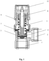
- FIG. 1 Another pressure relief valve made of brass, known in the state of the art (of the RBM manufacturer) is also calibrated in production and does not allow to adjust opening pressure.
- the cross-section of the valve is shown in Fig. 1 .
- the valve consists of a metal valve body, a valve chamber connected to the valve inlet and the valve outlet, a diaphragm resting on the valve seat and pressed by a calibrated spring, and a closing cap equipped with an external thread.
- the safety relief valve contains a relief mechanism for manual control of the valve using a rotating wheel.
- the valve body When assembling the valve, the valve body is equipped with a diaphragm, the piston is fitted with a calibrated spring, and by turning and engaging the thread the closing cap firmly presses the diaphragm to the valve body with the calibrated spring.
- a ring-shaped anti-friction pad prevents damage to the diaphragm when tightening the cap to the required torque.
- the pressure relief valve becomes unbreakable (it cannot be disassembled without damaging the cover), which complies with the applicable standards.
- the disadvantage of the described valve is that the set pressure cannot be adjusted, changing the set pressure is possible only by using a different spring.
- the presented invention eliminates this disadvantage and enables fine adjustment of the nominal pressure of the valve no need to replace the calibrated spring, while the adjustment refers only to the cap closing the valve in its upper part.
- An adjustable pressure relief valve intended for heating devices with a closed circuit of a heating medium, with a valve body equipped with a valve inlet and a valve outlet connected to a valve chamber, with a piston movably arranged in the valve chamber, on which there is a calibrated spring and a flexible closing diaphragm arranged.
- the valve In the normal state, when the calibrated spring is pressing on the flexible closing diaphragm, the valve is closed, and it is characterized by the fact that the valve is equipped with a two-part closing assembly, including an upper cap and a lower cap, for accurate setting of the nominal opening pressure by compressing the calibrated spring.
- the upper cap is equipped with a thread to compress the spring and the lower cap is equipped with a stop to prevent the upper cap from being completely unscrewed.
- the calibrated spring is located between the upper cap and the piston. Spring compression can be finely adjusted by turning the upper cap and engaging the spring compression thread.
- the lower cap is equipped with a thread to press the diaphragm to the valve body.
- the safety relief valve is equipped with a relief mechanism to open the valve manually and to fix the two-piece closing assembly in the set position.
- the relief mechanism is advantageously equipped with a joint and a lever, after its installation both caps are fixed in the set positions and the valve cannot be disassembled without damage.
- the valve is advantageously made of plastic, only the calibrated spring is metal.
- Fig. 1 shows a brass valve from the RBM manufacturer - only for illustration and for better understanding of the advantages of the presented invention compared to the state of the art.
- the valve known in the state of the art, is equipped with a closing cap 6, which is used to press the diaphragm 4 against the body 3 of the valve.
- the closing cap 6 does not allow the spring 5 to be pressed.
- the relief mechanism 12 is designed here as a relief mechanism for manual control of the valve using a rotating wheel.
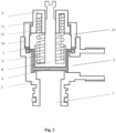
- Fig. 2 shows a model of a pressure relief valve according to the presented invention.
- An adjustable pressure relief valve intended for heating devices with a closed circuit of a heating medium, with a valve body 3 equipped with a valve inlet 1 and a valve outlet 2 connected to a valve chamber.
- the safety relief valve is equipped with a two-part closing assembly, including an upper cap 9 and a lower cap 10 for pressing the diaphragm 4 to the valve body 3.
- the calibrated spring 5 is inserted between the upper cap 9 and the piston 8 during assembly.
- the upper cap 9 is equipped with a thread 13.
- the lower cap 10 is equipped with a stop 11 preventing the upper cap 9 from being completely unscrewed.
- the lower cap 10 is also equipped with a thread 14 to press the diaphragm 4 to the body 3 of the valve by means of a calibrated spring 5.
- anti-friction pad 7 arranged between the lower cap 10 and the diaphragm 4 to protect the diaphragm 4 from damage.
- the pressure relief valve can be finely adjusted by turning the upper cap 9, while the spring 5 is compressed.
- the relief mechanism (not shown) is advantageously equipped with a joint and a lever and is used for manual opening of the valve (service).
- the two-piece closing assembly including the upper cap 9 and the lower cap 10, is fixed in a set position and the valve cannot be disassembled without damage.
- the nominal pressure which the safety relief valve is calibrated to is, for example, 3 bars.
- the valve is advantageously made of plastic, only the calibrated spring is metal.
- the adjustable pressure relief valve is designed to prevent exceeding the value set in a heating device with a closed circuit of a heating medium by discharging the medium from the system when the pressure of the medium in the device rises above the nominal value set.
Landscapes
- Engineering & Computer Science (AREA)
- General Engineering & Computer Science (AREA)
- Mechanical Engineering (AREA)
- Physics & Mathematics (AREA)
- Thermal Sciences (AREA)
- Chemical & Material Sciences (AREA)
- Combustion & Propulsion (AREA)
- Safety Valves (AREA)
Abstract
Description
- The invention refers to an adjustable pressure relief valve intended for use in a heating device with a closed circuit of a heating medium.
- The invention refers to a pressure relief valve, which is commonly used in heating devices with a closed circuit of a heating medium, for example in hanging hot water boilers, to release pressure exceeding the predetermined nominal value of the valve, which may occur for various reasons in the heating system during operation.
- The valves of this type use a diaphragm that keeps the valve in a closed position by means of a suitably calibrated spring depending on the operating pressure of the boiler or heating device.
- The pressure relief valve is an automatic valve and ensures that the pressure of the medium in the system does not exceed the set value, which plays an important role in the safety and operation of the device.
- It prevents exceeding the set value in the pipeline or in the equipment by discharging the medium from the system when the pressure of the medium in the equipment or pipeline rises above the set value.
- Parts and fittings of water supply systems, such as valves, were historically made of metal, usually brass, and were able to withstand water pressures significantly higher than that of a standard water supply system which a heating device is connected to.
- Currently, plastics, especially composites, have fully replaced metal in many applications, as they are sufficiently durable in devices working with normal water pressure in heating systems. By shaping the body from plastic material, it is possible to give the valve body or its part any functional shape, and therefore it is possible to produce a valve of a very simple design.
- The pressure relief valve is fully assembled and calibrated during production and has the properties required by the applicable hydraulic standards, in particular
- it must ensure simple assembly (for example, in the design of a cartridge valve, connected to a holder, with a bayonet or fork connection, secured with a clip, etc.)
- it must be equipped with a relief mechanism, allowing manual discharge of the medium when servicing the device (for example, using a rotating wheel or a lever)
- the safety relief valve must be as small as possible, as it is normally mounted in hydraulic modules
- Pressure relief valves made of plastic materials intended for use in heating devices are known in the state of the art.
-
EP 1 242 762 B1 -
FR2872881A3
Calibration of the value of the opening pressure of the valve is possible, in the example shown, the threaded sleeve is guided along a rod, which is an integral part of the cap. The rod is threaded, and when it rotates, it is possible to move the threaded sleeve which the spring rests against. - Such a design of a safety relief valve is complicated.
- Another pressure relief valve made of brass, known in the state of the art (of the RBM manufacturer) is also calibrated in production and does not allow to adjust opening pressure. The cross-section of the valve is shown in
Fig. 1 . - The valve consists of a metal valve body, a valve chamber connected to the valve inlet and the valve outlet, a diaphragm resting on the valve seat and pressed by a calibrated spring, and a closing cap equipped with an external thread. The safety relief valve contains a relief mechanism for manual control of the valve using a rotating wheel.
- When assembling the valve, the valve body is equipped with a diaphragm, the piston is fitted with a calibrated spring, and by turning and engaging the thread the closing cap firmly presses the diaphragm to the valve body with the calibrated spring.
- A ring-shaped anti-friction pad prevents damage to the diaphragm when tightening the cap to the required torque.
- When the relief mechanism with the cover is mounted, the pressure relief valve becomes unbreakable (it cannot be disassembled without damaging the cover), which complies with the applicable standards.
- The disadvantage of the described valve is that the set pressure cannot be adjusted, changing the set pressure is possible only by using a different spring.
- The impossibility of setting the pressure or finer adjustment of the valve turns out to be problematic, as the springs used in safety relief valves have their own tolerances, and therefore it is not possible to set the opening pressure to the nominal value accurately.
- The presented invention eliminates this disadvantage and enables fine adjustment of the nominal pressure of the valve no need to replace the calibrated spring, while the adjustment refers only to the cap closing the valve in its upper part.
- An adjustable pressure relief valve, intended for heating devices with a closed circuit of a heating medium, with a valve body equipped with a valve inlet and a valve outlet connected to a valve chamber, with a piston movably arranged in the valve chamber, on which there is a calibrated spring and a flexible closing diaphragm arranged. In the normal state, when the calibrated spring is pressing on the flexible closing diaphragm, the valve is closed, and it is characterized by the fact that the valve is equipped with a two-part closing assembly, including an upper cap and a lower cap, for accurate setting of the nominal opening pressure by compressing the calibrated spring.
- The upper cap is equipped with a thread to compress the spring and the lower cap is equipped with a stop to prevent the upper cap from being completely unscrewed.
- The calibrated spring is located between the upper cap and the piston. Spring compression can be finely adjusted by turning the upper cap and engaging the spring compression thread.
- The lower cap is equipped with a thread to press the diaphragm to the valve body. There is an anti-friction
pad arranged between the lower cap and the diaphragm to protect the diaphragm from damage. By turning and engaging the thread, the diaphragm is firmly pressed against the valve body by means of the calibrated spring. - The safety relief valve is equipped with a relief mechanism to open the valve manually and to fix the two-piece closing assembly in the set position. The relief mechanism is advantageously equipped with a joint and a lever, after its installation both caps are fixed in the set positions and the valve cannot be disassembled without damage.
- The valve is advantageously made of plastic, only the calibrated spring is metal.
- The invention is further explained using the figures below, without limitation thereto. The figures show:
-
Fig. 1 - a brass valve of the RBM manufacturer (the state of the art known) in cross-section -
Fig. 2 - a plastic valve according to the presented invention with a split closing cap - in cross-section -
Fig. 1 shows a brass valve from the RBM manufacturer - only for illustration and for better understanding of the advantages of the presented invention compared to the state of the art. The valve, known in the state of the art, is equipped with aclosing cap 6, which is used to press thediaphragm 4 against thebody 3 of the valve. Theclosing cap 6 does not allow thespring 5 to be pressed. Therelief mechanism 12 is designed here as a relief mechanism for manual control of the valve using a rotating wheel. -
Fig. 2 shows a model of a pressure relief valve according to the presented invention. - An adjustable pressure relief valve, intended for heating devices with a closed circuit of a heating medium, with a
valve body 3 equipped with avalve inlet 1 and avalve outlet 2 connected to a valve chamber. - There is a
piston 8 movably arranged in the valve chamber and there is a calibratedspring 5 arranged on thepiston 8. There is aflexible closing diaphragm 4 in the valve chamber between theinlet 1 and theoutlet 2, which is pressed by aspring 5 so that the valve is closed in the normal state. - The safety relief valve is equipped with a two-part closing assembly, including an
upper cap 9 and alower cap 10 for pressing thediaphragm 4 to thevalve body 3. - The calibrated
spring 5 is inserted between theupper cap 9 and thepiston 8 during assembly. To compress thespring 5, theupper cap 9 is equipped with athread 13. - The
lower cap 10 is equipped with astop 11 preventing theupper cap 9 from being completely unscrewed. - The
lower cap 10 is also equipped with athread 14 to press thediaphragm 4 to thebody 3 of the valve by means of a calibratedspring 5. - There is an
anti-friction pad 7 arranged between thelower cap 10 and thediaphragm 4 to protect thediaphragm 4 from damage. - The pressure relief valve can be finely adjusted by turning the
upper cap 9, while thespring 5 is compressed. - The relief mechanism (not shown) is advantageously equipped with a joint and a lever and is used for manual opening of the valve (service).
- When the relief mechanism is mounted, the two-piece closing assembly, including the
upper cap 9 and thelower cap 10, is fixed in a set position and the valve cannot be disassembled without damage. - The nominal pressure which the safety relief valve is calibrated to is, for example, 3 bars.
- The valve is advantageously made of plastic, only the calibrated spring is metal.
- The adjustable pressure relief valve is designed to prevent exceeding the value set in a heating device with a closed circuit of a heating medium by discharging the medium from the system when the pressure of the medium in the device rises above the nominal value set.
- It can also be used in other devices and its advantage is the possibility to set the nominal pressure accurately.
-
- 1 valve inlet
- 2 valve outlet
- 3 valve body
- 4 diaphragm
- 5 spring
- 6 closing cap
- 7 anti-friction pad
- 8 piston
- 9 upper cap
- 10 lower cap
- 11 stop
- 12 manual relief mechanism
- 13 thread
- 14 thread
Claims (5)
- An adjustable pressure relief valve, intended for heating devices with a closed circuit of a heating medium, with a valve body equipped with a valve inlet and a valve outlet connected to a valve chamber, with a piston movably arranged in the valve chamber, on which there is a calibrated spring and a flexible closing diaphragm arranged, wherein the valve is closed in the normal state under the pressure of the calibrated spring on the flexible closing diaphragm,
characterized in that
the valve is equipped with a two-part closing assembly, including an upper cap (9) and a lower cap (10) for accurate setting of the nominal opening pressure. - The adjustable pressure relief valve, according to claim 1,
characterized in that
the upper cap (9) is equipped with a thread (13) to compress the spring (5) and the lower cap (10) is equipped with a stop (11) to prevent the upper cap (9) from being completely unscrewed. - The adjustable pressure relief valve, according to claim 1 or 2,
characterized in that
the lower cap (10) is equipped with a thread (14) to press the diaphragm (4) to the body (3) of the valve. - The adjustable pressure relief valve according to any of the preceding claims, characterized in that
there is an anti-friction pad (7) arranged between the lower cap (10) and the diaphragm (4) to protect the diaphragm (4) from damage. - The adjustable pressure relief valve according to any of the preceding claims, characterized in that
it is equipped with a relief mechanism to open the valve manually and to fix the two-piece closing assembly in the set position.
Applications Claiming Priority (1)
| Application Number | Priority Date | Filing Date | Title |
|---|---|---|---|
| SK1252021U SK9533Y1 (en) | 2021-08-31 | 2021-08-31 | Adjustable pressure relief valve |
Publications (2)
| Publication Number | Publication Date |
|---|---|
| EP4141304A1 true EP4141304A1 (en) | 2023-03-01 |
| EP4141304B1 EP4141304B1 (en) | 2025-07-09 |
Family
ID=80123542
Family Applications (1)
| Application Number | Title | Priority Date | Filing Date |
|---|---|---|---|
| EP22193339.3A Active EP4141304B1 (en) | 2021-08-31 | 2022-08-31 | Adjustable pressure relief valve |
Country Status (2)
| Country | Link |
|---|---|
| EP (1) | EP4141304B1 (en) |
| SK (1) | SK9533Y1 (en) |
Citations (9)
| Publication number | Priority date | Publication date | Assignee | Title |
|---|---|---|---|---|
| FR2498306A3 (en) * | 1981-01-22 | 1982-07-23 | Copreci Ind Sci | Security valve for electric water heater - has multi function valves allowing closure, supply and pressure release |
| EP0648965A1 (en) * | 1993-10-15 | 1995-04-19 | Hans Sasserath & Co Kg | Module for a membrane safety valve to be mounted in a valve housing |
| FR2748541A3 (en) * | 1996-05-10 | 1997-11-14 | Macrifin Spa | Automatic safety valve for pressurised hot water reservoirs |
| EP1279875A2 (en) * | 2001-07-23 | 2003-01-29 | Vaillant GmbH | Method for dimensioning a spring loaded valve and valve made according to this method |
| US20040036050A1 (en) * | 2002-05-30 | 2004-02-26 | Kerg David C. | Rotary valve actuator |
| EP1242762B1 (en) | 1999-12-06 | 2004-09-22 | GIACOMINI S.p.A. | Safety valve assembly |
| FR2872881A3 (en) | 2004-07-09 | 2006-01-13 | Caleffi Spa | Safety valve for wall-mounted boiler`s hydraulic control group, has valve body molded in plastic material and presenting blades which form part of bayonet shaped connection system, and water outlet conduit presenting flat shape section |
| DE102010045280A1 (en) * | 2010-09-14 | 2012-03-15 | Honeywell Technologies Sarl | Pressure relief valve i.e. safety valve, for protecting boiler against high pressure, has valve seat, valve body and spring element forming valve insert, which is mountable as unit in valve housing and demountable as unit from housing |
| CN104989856A (en) * | 2015-07-07 | 2015-10-21 | 海宁市倍世环保科技有限公司 | Pressure control and stabilizing device |
-
2021
- 2021-08-31 SK SK1252021U patent/SK9533Y1/en unknown
-
2022
- 2022-08-31 EP EP22193339.3A patent/EP4141304B1/en active Active
Patent Citations (9)
| Publication number | Priority date | Publication date | Assignee | Title |
|---|---|---|---|---|
| FR2498306A3 (en) * | 1981-01-22 | 1982-07-23 | Copreci Ind Sci | Security valve for electric water heater - has multi function valves allowing closure, supply and pressure release |
| EP0648965A1 (en) * | 1993-10-15 | 1995-04-19 | Hans Sasserath & Co Kg | Module for a membrane safety valve to be mounted in a valve housing |
| FR2748541A3 (en) * | 1996-05-10 | 1997-11-14 | Macrifin Spa | Automatic safety valve for pressurised hot water reservoirs |
| EP1242762B1 (en) | 1999-12-06 | 2004-09-22 | GIACOMINI S.p.A. | Safety valve assembly |
| EP1279875A2 (en) * | 2001-07-23 | 2003-01-29 | Vaillant GmbH | Method for dimensioning a spring loaded valve and valve made according to this method |
| US20040036050A1 (en) * | 2002-05-30 | 2004-02-26 | Kerg David C. | Rotary valve actuator |
| FR2872881A3 (en) | 2004-07-09 | 2006-01-13 | Caleffi Spa | Safety valve for wall-mounted boiler`s hydraulic control group, has valve body molded in plastic material and presenting blades which form part of bayonet shaped connection system, and water outlet conduit presenting flat shape section |
| DE102010045280A1 (en) * | 2010-09-14 | 2012-03-15 | Honeywell Technologies Sarl | Pressure relief valve i.e. safety valve, for protecting boiler against high pressure, has valve seat, valve body and spring element forming valve insert, which is mountable as unit in valve housing and demountable as unit from housing |
| CN104989856A (en) * | 2015-07-07 | 2015-10-21 | 海宁市倍世环保科技有限公司 | Pressure control and stabilizing device |
Also Published As
| Publication number | Publication date |
|---|---|
| SK1252021U1 (en) | 2022-02-09 |
| SK9533Y1 (en) | 2022-06-15 |
| EP4141304B1 (en) | 2025-07-09 |
Similar Documents
| Publication | Publication Date | Title |
|---|---|---|
| EP2376991B1 (en) | Internal relief valve apparatus for use with loading regulators | |
| US6892756B2 (en) | Gas flow monitoring device | |
| CN101903691B (en) | Control valve | |
| CN211924897U (en) | Fluid distribution system, assembly for reducing excessive pipeline pressure of fluid distribution system and fluid regulator | |
| US11746917B2 (en) | Pressure regulator with outlet overpressure security | |
| US11703893B2 (en) | Gas pressure reducer with cam commanded shut-off valve | |
| US8500092B2 (en) | Secondary seat for gas regulator | |
| KR101253666B1 (en) | Fluid controlling valve | |
| RU2643113C2 (en) | Input control for symmetric input | |
| US20130153058A1 (en) | Pressure reducer | |
| CN101978333B (en) | Pressure-actuated member, in particular paint pressure controller or coating agent valve | |
| US3603333A (en) | Pressure relief valve | |
| CN117203598A (en) | Compact field calibrated pressure reducing valve | |
| JP2007529693A (en) | Check valve | |
| EP4141304B1 (en) | Adjustable pressure relief valve | |
| US3747635A (en) | Pressure relief control valve | |
| EP1813846A2 (en) | Safety valve for fluids | |
| CN105814354A (en) | Apparatus for setting and verifying set point on a valve assembly | |
| EP2522891B1 (en) | Double regulating balancing valve | |
| CN220416356U (en) | Under-pressure adjustable self-closing valve | |
| WO2009046714A3 (en) | Adjustable pressure reduction valve | |
| WO2018124907A1 (en) | Axial gas pressure regulator | |
| CA3045013C (en) | Axial gas pressure regulator | |
| DE10159166C2 (en) | Pressure regulator sensor | |
| PL177402B1 (en) | Gas pressure regulating valve, especially that with manual pressure adjustment |
Legal Events
| Date | Code | Title | Description |
|---|---|---|---|
| PUAI | Public reference made under article 153(3) epc to a published international application that has entered the european phase |
Free format text: ORIGINAL CODE: 0009012 |
|
| STAA | Information on the status of an ep patent application or granted ep patent |
Free format text: STATUS: THE APPLICATION HAS BEEN PUBLISHED |
|
| AK | Designated contracting states |
Kind code of ref document: A1 Designated state(s): AL AT BE BG CH CY CZ DE DK EE ES FI FR GB GR HR HU IE IS IT LI LT LU LV MC MK MT NL NO PL PT RO RS SE SI SK SM TR |
|
| STAA | Information on the status of an ep patent application or granted ep patent |
Free format text: STATUS: REQUEST FOR EXAMINATION WAS MADE |
|
| 17P | Request for examination filed |
Effective date: 20230818 |
|
| RBV | Designated contracting states (corrected) |
Designated state(s): AL AT BE BG CH CY CZ DE DK EE ES FI FR GB GR HR HU IE IS IT LI LT LU LV MC MK MT NL NO PL PT RO RS SE SI SK SM TR |
|
| GRAP | Despatch of communication of intention to grant a patent |
Free format text: ORIGINAL CODE: EPIDOSNIGR1 |
|
| STAA | Information on the status of an ep patent application or granted ep patent |
Free format text: STATUS: GRANT OF PATENT IS INTENDED |
|
| INTG | Intention to grant announced |
Effective date: 20250212 |
|
| GRAS | Grant fee paid |
Free format text: ORIGINAL CODE: EPIDOSNIGR3 |
|
| GRAA | (expected) grant |
Free format text: ORIGINAL CODE: 0009210 |
|
| STAA | Information on the status of an ep patent application or granted ep patent |
Free format text: STATUS: THE PATENT HAS BEEN GRANTED |
|
| AK | Designated contracting states |
Kind code of ref document: B1 Designated state(s): AL AT BE BG CH CY CZ DE DK EE ES FI FR GB GR HR HU IE IS IT LI LT LU LV MC MK MT NL NO PL PT RO RS SE SI SK SM TR |
|
| REG | Reference to a national code |
Ref country code: GB Ref legal event code: FG4D |
|
| REG | Reference to a national code |
Ref country code: CH Ref legal event code: EP |
|
| REG | Reference to a national code |
Ref country code: IE Ref legal event code: FG4D |
|
| REG | Reference to a national code |
Ref country code: DE Ref legal event code: R096 Ref document number: 602022017228 Country of ref document: DE |
|
| PGFP | Annual fee paid to national office [announced via postgrant information from national office to epo] |
Ref country code: DE Payment date: 20250730 Year of fee payment: 4 |
|
| PGFP | Annual fee paid to national office [announced via postgrant information from national office to epo] |
Ref country code: FR Payment date: 20250826 Year of fee payment: 4 |
|
| REG | Reference to a national code |
Ref country code: NL Ref legal event code: MP Effective date: 20250709 |
|
| PG25 | Lapsed in a contracting state [announced via postgrant information from national office to epo] |
Ref country code: PT Free format text: LAPSE BECAUSE OF FAILURE TO SUBMIT A TRANSLATION OF THE DESCRIPTION OR TO PAY THE FEE WITHIN THE PRESCRIBED TIME-LIMIT Effective date: 20251110 |
|
| PG25 | Lapsed in a contracting state [announced via postgrant information from national office to epo] |
Ref country code: NL Free format text: LAPSE BECAUSE OF FAILURE TO SUBMIT A TRANSLATION OF THE DESCRIPTION OR TO PAY THE FEE WITHIN THE PRESCRIBED TIME-LIMIT Effective date: 20250709 |
|
| REG | Reference to a national code |
Ref country code: AT Ref legal event code: MK05 Ref document number: 1812080 Country of ref document: AT Kind code of ref document: T Effective date: 20250709 |
|
| PG25 | Lapsed in a contracting state [announced via postgrant information from national office to epo] |
Ref country code: IS Free format text: LAPSE BECAUSE OF FAILURE TO SUBMIT A TRANSLATION OF THE DESCRIPTION OR TO PAY THE FEE WITHIN THE PRESCRIBED TIME-LIMIT Effective date: 20251109 |
|
| PG25 | Lapsed in a contracting state [announced via postgrant information from national office to epo] |
Ref country code: NO Free format text: LAPSE BECAUSE OF FAILURE TO SUBMIT A TRANSLATION OF THE DESCRIPTION OR TO PAY THE FEE WITHIN THE PRESCRIBED TIME-LIMIT Effective date: 20251009 |
|
| REG | Reference to a national code |
Ref country code: LT Ref legal event code: MG9D |
|
| PG25 | Lapsed in a contracting state [announced via postgrant information from national office to epo] |
Ref country code: AT Free format text: LAPSE BECAUSE OF FAILURE TO SUBMIT A TRANSLATION OF THE DESCRIPTION OR TO PAY THE FEE WITHIN THE PRESCRIBED TIME-LIMIT Effective date: 20250709 |
|
| PG25 | Lapsed in a contracting state [announced via postgrant information from national office to epo] |
Ref country code: FI Free format text: LAPSE BECAUSE OF FAILURE TO SUBMIT A TRANSLATION OF THE DESCRIPTION OR TO PAY THE FEE WITHIN THE PRESCRIBED TIME-LIMIT Effective date: 20250709 |
|
| PG25 | Lapsed in a contracting state [announced via postgrant information from national office to epo] |
Ref country code: HR Free format text: LAPSE BECAUSE OF FAILURE TO SUBMIT A TRANSLATION OF THE DESCRIPTION OR TO PAY THE FEE WITHIN THE PRESCRIBED TIME-LIMIT Effective date: 20250709 |
|
| PG25 | Lapsed in a contracting state [announced via postgrant information from national office to epo] |
Ref country code: GR Free format text: LAPSE BECAUSE OF FAILURE TO SUBMIT A TRANSLATION OF THE DESCRIPTION OR TO PAY THE FEE WITHIN THE PRESCRIBED TIME-LIMIT Effective date: 20251010 |
|
| PG25 | Lapsed in a contracting state [announced via postgrant information from national office to epo] |
Ref country code: SE Free format text: LAPSE BECAUSE OF FAILURE TO SUBMIT A TRANSLATION OF THE DESCRIPTION OR TO PAY THE FEE WITHIN THE PRESCRIBED TIME-LIMIT Effective date: 20250709 |
|
| PG25 | Lapsed in a contracting state [announced via postgrant information from national office to epo] |
Ref country code: LV Free format text: LAPSE BECAUSE OF FAILURE TO SUBMIT A TRANSLATION OF THE DESCRIPTION OR TO PAY THE FEE WITHIN THE PRESCRIBED TIME-LIMIT Effective date: 20250709 |
|
| PG25 | Lapsed in a contracting state [announced via postgrant information from national office to epo] |
Ref country code: PL Free format text: LAPSE BECAUSE OF FAILURE TO SUBMIT A TRANSLATION OF THE DESCRIPTION OR TO PAY THE FEE WITHIN THE PRESCRIBED TIME-LIMIT Effective date: 20250709 Ref country code: BG Free format text: LAPSE BECAUSE OF FAILURE TO SUBMIT A TRANSLATION OF THE DESCRIPTION OR TO PAY THE FEE WITHIN THE PRESCRIBED TIME-LIMIT Effective date: 20250709 |
|
| PG25 | Lapsed in a contracting state [announced via postgrant information from national office to epo] |
Ref country code: RS Free format text: LAPSE BECAUSE OF FAILURE TO SUBMIT A TRANSLATION OF THE DESCRIPTION OR TO PAY THE FEE WITHIN THE PRESCRIBED TIME-LIMIT Effective date: 20251009 |
|
| PG25 | Lapsed in a contracting state [announced via postgrant information from national office to epo] |
Ref country code: ES Free format text: LAPSE BECAUSE OF FAILURE TO SUBMIT A TRANSLATION OF THE DESCRIPTION OR TO PAY THE FEE WITHIN THE PRESCRIBED TIME-LIMIT Effective date: 20250709 |
|
| PG25 | Lapsed in a contracting state [announced via postgrant information from national office to epo] |
Ref country code: RO Free format text: LAPSE BECAUSE OF FAILURE TO SUBMIT A TRANSLATION OF THE DESCRIPTION OR TO PAY THE FEE WITHIN THE PRESCRIBED TIME-LIMIT Effective date: 20250709 |
|
| REG | Reference to a national code |
Ref country code: CH Ref legal event code: H13 Free format text: ST27 STATUS EVENT CODE: U-0-0-H10-H13 (AS PROVIDED BY THE NATIONAL OFFICE) Effective date: 20260324 |
|
| PG25 | Lapsed in a contracting state [announced via postgrant information from national office to epo] |
Ref country code: SM Free format text: LAPSE BECAUSE OF FAILURE TO SUBMIT A TRANSLATION OF THE DESCRIPTION OR TO PAY THE FEE WITHIN THE PRESCRIBED TIME-LIMIT Effective date: 20250709 |
|
| PG25 | Lapsed in a contracting state [announced via postgrant information from national office to epo] |
Ref country code: DK Free format text: LAPSE BECAUSE OF FAILURE TO SUBMIT A TRANSLATION OF THE DESCRIPTION OR TO PAY THE FEE WITHIN THE PRESCRIBED TIME-LIMIT Effective date: 20250709 |
|
| PG25 | Lapsed in a contracting state [announced via postgrant information from national office to epo] |
Ref country code: IT Free format text: LAPSE BECAUSE OF FAILURE TO SUBMIT A TRANSLATION OF THE DESCRIPTION OR TO PAY THE FEE WITHIN THE PRESCRIBED TIME-LIMIT Effective date: 20250709 Ref country code: LU Free format text: LAPSE BECAUSE OF NON-PAYMENT OF DUE FEES Effective date: 20250831 |
|
| PG25 | Lapsed in a contracting state [announced via postgrant information from national office to epo] |
Ref country code: CH Free format text: LAPSE BECAUSE OF NON-PAYMENT OF DUE FEES Effective date: 20250831 Ref country code: CZ Free format text: LAPSE BECAUSE OF FAILURE TO SUBMIT A TRANSLATION OF THE DESCRIPTION OR TO PAY THE FEE WITHIN THE PRESCRIBED TIME-LIMIT Effective date: 20250709 |
|
| PG25 | Lapsed in a contracting state [announced via postgrant information from national office to epo] |
Ref country code: EE Free format text: LAPSE BECAUSE OF FAILURE TO SUBMIT A TRANSLATION OF THE DESCRIPTION OR TO PAY THE FEE WITHIN THE PRESCRIBED TIME-LIMIT Effective date: 20250709 Ref country code: SK Free format text: LAPSE BECAUSE OF FAILURE TO SUBMIT A TRANSLATION OF THE DESCRIPTION OR TO PAY THE FEE WITHIN THE PRESCRIBED TIME-LIMIT Effective date: 20250709 |
|
| PLBE | No opposition filed within time limit |
Free format text: ORIGINAL CODE: 0009261 |
|
| STAA | Information on the status of an ep patent application or granted ep patent |
Free format text: STATUS: NO OPPOSITION FILED WITHIN TIME LIMIT |