EP1242762B1 - Safety valve assembly - Google Patents
Safety valve assembly Download PDFInfo
- Publication number
- EP1242762B1 EP1242762B1 EP00989950A EP00989950A EP1242762B1 EP 1242762 B1 EP1242762 B1 EP 1242762B1 EP 00989950 A EP00989950 A EP 00989950A EP 00989950 A EP00989950 A EP 00989950A EP 1242762 B1 EP1242762 B1 EP 1242762B1
- Authority
- EP
- European Patent Office
- Prior art keywords
- cartridge
- cartridge holder
- valve
- holder
- housing
- Prior art date
- Legal status (The legal status is an assumption and is not a legal conclusion. Google has not performed a legal analysis and makes no representation as to the accuracy of the status listed.)
- Expired - Lifetime
Links
Images


Classifications
-
- F—MECHANICAL ENGINEERING; LIGHTING; HEATING; WEAPONS; BLASTING
- F16—ENGINEERING ELEMENTS AND UNITS; GENERAL MEASURES FOR PRODUCING AND MAINTAINING EFFECTIVE FUNCTIONING OF MACHINES OR INSTALLATIONS; THERMAL INSULATION IN GENERAL
- F16K—VALVES; TAPS; COCKS; ACTUATING-FLOATS; DEVICES FOR VENTING OR AERATING
- F16K17/00—Safety valves; Equalising valves, e.g. pressure relief valves
- F16K17/02—Safety valves; Equalising valves, e.g. pressure relief valves opening on surplus pressure on one side; closing on insufficient pressure on one side
- F16K17/04—Safety valves; Equalising valves, e.g. pressure relief valves opening on surplus pressure on one side; closing on insufficient pressure on one side spring-loaded
- F16K17/0446—Safety valves; Equalising valves, e.g. pressure relief valves opening on surplus pressure on one side; closing on insufficient pressure on one side spring-loaded with an obturating member having at least a component of their opening and closing motion not perpendicular to the closing faces
- F16K17/0453—Safety valves; Equalising valves, e.g. pressure relief valves opening on surplus pressure on one side; closing on insufficient pressure on one side spring-loaded with an obturating member having at least a component of their opening and closing motion not perpendicular to the closing faces the member being a diaphragm
Definitions
- the present invention relates to a cartridge valve and cartridge holder safety valve assembly for liquid or gaseous fluid circuits, according to the preamble of claim 1.
- cartridge valve and cartridge holder safety valve assemblies for liquid or gaseous fluid systems are used in all those applications in which, for safety reasons, it is necessary to automatically perform a fluid releasing operation as the related pressure exceeds a predetermined value set in the safety valve, for example in heating systems in which the valve and cartridge holder assembly may be mounted on the circulating pump support generally arranged under the boiler, or at a location of difficult access and poorly lightened.
- the mentioned safety valves in the form of cartridges to be removably engaged in a T-shape cartridge holder provided, on the same axis, with a fitting having a cartridge valve housing chamber as well as a related connection fitting, for example for connection with the pump supporting body, and an orthogonal fluid outlet fitting communicating with said valve cartridge housing chamber through windows formed through the cartridge body.
- a cartridge valve cover element is removably engaged with an inner insert of the cartridge pertaining to a calibrating spring assembly, thereby preventing the calibrating portions of the safety cartridge valve from being accessed.
- the cup sealing gasket of the valve is arranged on the open bottom of the cartridge, outside of the latter and, upon assembling the cartridge in the cartridge holder, said sealing gasket will operatively abut against a seat formed in the cartridge holder.
- This is affected by two drawbacks. On a side, the cup sealing gasket can be freely accessed during the handling of the valve, with consequent possible damages of said valve, thereby prior safety valves of this type are not truly "inviolable", even if they would be defined as such.
- a further disadvantage of prior safety valves of the above mentioned type is that the application of said valves, for example on the pump supporting body, or the like, would always require a use of a cartridge holder fitting. This would be consequently very expensive both due to the cartridge holder fining cost and the machining costs related to the necessary machining operation to provide on the pump support, or other like support, a cartridge holder fitting housing seat as well as to use the necessary sealing means, usually comprising O-ring elements.
- prior safety valves require complex coupling means for connecting the cartridge valve and cartridge holder.
- these prior coupling means also require a rather skilled assembling operator who must frequently carry out the assembling/disassembling of the cartridge safety valve in a very small space of difficult access and poorly lightened.
- the aim of the present invention is to provide a cartridge valve and cartridge holder safety valve assembly of the type mentioned in the preamble, which overcomes the disadvantages and drawbacks of the prior inviolable cartridge valve and cartridge holder safety valves while allowing the cartridge valve to be directly assembled both in a cartridge holder of a T-type and, alternately, in a cartridge holder formed by a circuit component designed for simultaneously performing other functions, such as a supporting body for supporting the circulating pump, or pump holder, and also adapted to be fitted to the cartridge holder in a very simple, quick and safe manner.
- a cartridge valve and cartridge holder safety valve assembly having the features of claim 1.
- the cartridge valve and cartridge holder safety valve assembly according to the invention provides a lot of important different advantages.
- a cartridge body having an independent cartridge body bottom allows to advantageously provide, on said bottom, a coupling lug, adapted to advantageously house a sealing element, for example an O-ring in a corresponding easily made housing seat.
- Said sealing element or O-ring could also be advantageously engaged in the seat housing said cartridge coupling lug and provided with a conventional T-shape cartridge holder, or a cartridge holder of different configuration, for example as a support for the circulating pump, as above mentioned, or the like.
- This alternative embodiment would clearly allow said inviolable cartridge safety valve to be directly assembled, for example, on the pump support thereby allowing to omit the prior T-shape cartridge holder fitting.
- This leaving out of the T-shape cartridge holder body would allow, in turn, to reduce the size of the cartridge and cartridge holder safety valve assembly, thereby facilitating the assembling/replacing of the cartridge valve even at locations of difficult access.
- Yet another important advantage is that a possible sealing failure due to abrasions or scorings of the seat cooperating with the safety valve cup gasket could be eliminated by a simple replacing of said inviolable cartridge safety valve, instead of replacing the overall cartridge and cartridge holder valve assembly, as necessary in the prior art.
- the removable coupling means for coupling the cartridge valve and cartridge holder can be partially made during the making of the body of the cartridge and cartridge holder and partially by simple chip removal machining operations, which could be performed in very small times during the machining of the body of the cartridge and cartridge holder, and this in a very unexpensive manner.
- the provided removable locking element would be very unexpensive, thereby said element, if lost, could be easily replaced in an optimum functional manner by a small metal wire length.
- a proper connection of the cartridge valve and cartridge holder can be performed likewise by parts to be directly made by molding on the cartridge and cartridge holder body, thereby also these parts could be made in a very unexpensive and reliable manner.
- the cartridge holder in order to properly house the cartridge valve, the cartridge holder must be simply provided with a seat for housing the independent bottom or bottom end piece of the cartridge, instead of housing the bottom of the cup sealing gasket projecting from the cartridge, as in the prior art, thereby saving the cost associated with additional material or machining operations.
- Claim 4 allows to provide a perfect sealing between the cartridge valve and cartridge holder, by advantageously providing a conventional sealing element or O-ring which is housed either on the bottom or on the bottom end piece of the cartridge or in the seat of the cartridge holder housing therein said bottom or bottom end piece of the cartridge.
- claim 1 provides advantageous quick coupling means for quickly coupling the cartridge valve and cartridge holder, which quick coupling means can be made during the same molding and chip removal machining steps for making both the cartridge and the cartridge holder, thereby greatly reducing the machining cost for making them.
- claims 5, 6 and 7 relate to preferred embodiments of said quick coupling means for quickly coupling the cartridge and cartridge holder, said approaches providing a very simple and easy handling for performing the cartridge locking/unlocking operations, while providing a unique assembling location between the cartridge and cartridge holder even under difficult access and poor visibility conditions.
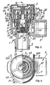
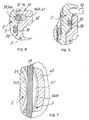
- the cartridge valve and cartridge holder inviolable safety valve assembly according to the present invention has been generally indicated by 1 (figures 1 to 7) and 1 A (figure 8).
- Said valve assembly being substantially constituted by an inviolable safety cartridge valve 2 and a cartridge holder element 3 (figures 1 to 7) and 3A (figure 8).
- the cartridge holder 3 has a T-shape, which is partially known, with a first fitting 4 defining a chamber 6 for housing herein the cartridge valve 2, a second coaxial fitting 7, to be coupled to the liquid and gaseous system, as well as a third orthogonal fitting 8 forming the fluid outlet, as the pressure in the circuit exceeds the value of the cartridge valve 2 calibrating pressure.
- a first fitting 4 defining a chamber 6 for housing herein the cartridge valve 2
- a second coaxial fitting 7 to be coupled to the liquid and gaseous system
- a third orthogonal fitting 8 forming the fluid outlet, as the pressure in the circuit exceeds the value of the cartridge valve 2 calibrating pressure.
- the inviolable safety cartridge valve 2 comprises, in a per partially known manner, a cartridge body 9, of substantially tubular configuration, with a plurality of perimetrical windows 11 and housed in its inside a calibrating assembly 10, the spring 12 of which is arranged between a piston element 13 and a calibrating threaded ring nut 14. As shown in the drawings, between the cartridge body 9 and threaded ring nut 14 is formed a gap 16 in which is housed the enlarged edge 17 of a sealing and reaction cup gasket 18, the bottom 19 of which fluidly contacts the circuit fluid and of which the safety valve 2 would set the maximum operating pressure.
- the body 9 of the cartridge is closed at the top thereof by a cover 21 which, as is shown in the drawing, can be engaged by a tubular lug 21A, with a fixed type of detent engagement, in the piston element 13.
- a cover 21 which, as is shown in the drawing, can be engaged by a tubular lug 21A, with a fixed type of detent engagement, in the piston element 13.
- any attempts to operate the pressure setting ring nut 14 provided for setting the calibrating pressure of the calibrating assembly 10 would cause the cover 21, generally made of a synthetic material, to be broken.
- the bottom of the sealing cup gaskets forms the bottom itself of the cartridge body 9, which is accordingly engaged against an annular seat formed in the cartridge holder and which, as above stated, could be abraded or scored.
- the cartridge body 9 is herein made, according to the invention, as a cup having an independent bottom 23 with a window pattern 24.
- the bottom 23 is provided, in the inside thereof, with the seat 26 for bearing thereagainst the bottom 19 of the sealing cup gasket 18 and, on the outside thereof, being provided with a tightly coupling lug 27 for providing a tight coupling with a corresponding housing seat 28 formed in the cartridge holder 3, corresponding to that which, in prior T-shape cartridge holders, was provided for receiving the cartridge valve cup gasket bottom.
- At least a sealing gasket is herein provided, for example in the form of an O-ring 29, which can be indifferently housed in the coupling lug 27 or in said seat 28 of the cartridge holder.
- the removable coupling means for removably coupling the cartridge body 9 and cartridge holder 3 are of a quick coupling type and being generally indicated by the reference number 31, and they will be disclosed in a more detailed manner hereinafter.
- a prior cartridge holder of a substantially T-shape, comprises now a housing chamber 6 for housing the cartridge valve 2, on the bottom of which chamber 6 is provided said seat 28 for tightly housing therein the bottom 23, 27 of the cartridge 2.
- the cartridge holder 3 body or fitting comprises a known coupling fitting 7 for providing a connection to a component, not shown, of the considered liquid or gaseous fluid system, as well as an outlet fitting 8 for releasing the fluid as the valve 2 calibrating pressure is exceeded.
- the cartridge holder 3A comprises any desired components of the considered liquid or gaseous fluid system, for example the pump supporting or holding body in the case of a heating system or a hot water producing system.
- the pump holder, or cartridge holder, 3A could accordingly also support possible mechanical or electric components.
- the pump holder 3A comprises said housing seat 28 for housing said bottom 23, 27 of the cartridge 2.
- the reference number 8A shows the outlet fitting.
- the pump and related mechanical and electric fixtures supported on said cartridge holder 30 have been omitted for simplicity, since they do not come within the scope of the present invention.
- said removable quick coupling means 31 comprises a removable locking element 33, for example a U-shape bracket made, for example, of a metal wire, as well as two diametrically opposite housing seats 34 for housing the wing portions 33A of the bracket 33, each said wing or leg being formed by a half-seat 34A provided on the body 9 of the cartridge 2 and a half-seat 34B provided on the cartridge holder 3; 3A in a mutual opposite relationship.
- the reference number 37 shows a sealing element, for example an O-ring, engaged in a corresponding annular slot 38 of the cartridge body 9.
- the two half-seats 34A of the cartridge 2 body 9 are formed by an annular slot 39, whereas the two half-seats 34B on the cartridge holder 3, 3A are formed by an annular slot length 41 formed in two diametrically opposite lugs 42 of the cartridge holder 3, 3A.
- locating lugs 43 are provided on the cartridge 2, said locating lugs cooperating with the coupling lugs 42 of the cartridge holder 3, 3A.
- said locating lugs 43 are formed by annular flange sectors, outward projecting, and the circumferential extension whereof substantially corresponds to the circumferential spacing of the mutually facing front sides 44 of the two coupling lugs 42 on the cartridge holder 3, 3A.
- the cartridge valve 2 can be freely engaged in the housing chamber 6 therefor in the cartridge holder fitting 3, without engaging in the seat 28 of the cartridge holder the bottom 19 of the cup gasket 18, as it occurs in prior valves, but, on the contrary, by engaging therein the coupling lug 27 of the cartridge bottom 23.
- This coupling can be performed as, by turning the cartridge 2 about its longitudinal axis, the gaps between the locating lugs 43 are brought above the lugs 42 of the body of the cartridge holder 3.
- the cartridge body 9 can be fully introduced into the chamber 6, and, in this position, at least one of the windows of the cartridge body 9 will be arranged in front of the outlet window 46 of the cartridge holder 3, 3a.
- the wing or leg portions 33A of the wire bracket 33 can be engaged in the straight throughgoing paths formed between the opposite half-seats 34A and 34B, thereby the insertion of the bracket 33 into the cartridge holder will provide a finn mutual locking of the cartridge holder 3; 3A and cartridge valve 2.
- the valve assembly 1, or 2-3 will be then ready to be fixed in the known pump holder body, not shown, of a heating system, a hot water producing system, or the like.
- a removal of the cartridge valve 2 assembled in the cartridge holder 3; 3A would simply require a removal of the locking bracket 33 which can be simply carried out by disengaging the wing portions 33A of the bracket 33 from the related removable quick coupling means 31.
- the assembling of the cleaned cartridge valve, or the replacement of a new valve may be performed as hereinabove disclosed.
- the bottom 19 of the cup gasket 18 will be held in abutment on the inner seat 20 of the bottom 23 of the cartridge 9, as urged by the spring 12.
- the fluid will cause the bottom 19 of the gasket 18 to be raised from the seat 20, against the calibrating spring 12 force, and will be outward discharged through the fitting 8, whereas the calibrating spring 12 will interrupt the discharging of the fluid as the pressure of the latter in the system will be recovered to a value less than the calibrating pressure value.
- valve assembly 1 of the embodiment shown in figures 1-7 can be directly applied to a conventional pump holder and that the same inviolable safety cartridge valve 2 according to the invention can be likewise applied, at will, directly on a pump holder 3A according to the invention, operating by itself as a cartridge holder 3A.
- a housing chamber 6A would be of course provided, for housing therein the cartridge valve 2 and with a related housing seat 28 for housing the bottom 23 of the cartridge 9, as well as the removable quick coupling means 31, or 34A, 42 as above disclosed with reference to the embodiment shown in figures 1 to 7.
Landscapes
- Engineering & Computer Science (AREA)
- General Engineering & Computer Science (AREA)
- Mechanical Engineering (AREA)
- Feeding And Controlling Fuel (AREA)
- Quick-Acting Or Multi-Walled Pipe Joints (AREA)
- Compressor (AREA)
- Glass Compositions (AREA)
- Control Of Combustion (AREA)
- Water Treatment By Sorption (AREA)
- Safety Valves (AREA)
Abstract
Description
Claims (7)
- A cartridge valve (2) and cartridge holder (3) inviolable safety valve assembly (1) for liquid or gaseous fluid systems, comprising:a) a substantially tubular cartridge body (9), provided with perimetrical windows (11),b) an adjustable spring assembly (10), housed in the body (9) of the cartridge and comprising a substantially cup-like gasket (18), the bottom (19) of which is affected by the fluid the maximum pressure whereof must be controlled,c) a cover (21) removably coupled to said cartridge body (9) and which can be separated only by breaking said cover (21),d) a cartridge holder (3) removably tightly housing a cartridge valve (2),e) wherein said cartridge valve (2) and said cartridge holder (3) are provided with removable coupling means (31),
characterized in that:f) the body (9) of the cartridge valve (2) is provided with an individual bottom (23) provided with windows (24) said body being provided, in the inside thereof, with a seat (20) for bearing thereagainst the bottom (19) of the cup gasket (18) and, on the outside thereof, with a tightly coupling lug (27) for providing a tight coupling with a corresponding housing seat (28) provided in the cartridge holder (3),g) there is provided at least a sealing gasket (29) between said bottom or coupling lug (27) of the cartridge valve (2) and said housing seat (28) provided on the body of said cartridge holder (3), andh) the removable coupling means (31) of the body (9) of the cartridge valve (2) and cartridge holder (3; 3A) are of a quick coupling type and comprisea removable locking element (33), for example in the form of a substantially U-shape bracket, for example made of a metal wire, andtwo diametrically opposite seats (34) each formed by a half seat (34A) formed on the cartridge body (9) and a half-scat (34B) formed on the cartridge holder (3; 3A), said half-seats (34A, 34B) being arranged in a mutual opposite relationship. - A cartridge valve and cartridge holder inviolable safety valve assembly according to Claim 1, characterized in that the cartridge holder (3), is formed by a fitting of substantially T-shape (3) comprising a housing chamber (6) for housing the cartridge valve (2), on the bottom of said chamber (6) being provided said tightly housing seat (28) for tightly housing the bottom (23, 27) of the cartridge (2).
- A cartridge valve and cartridge holder inviolable safety valve assembly according to Claim 1, characterized in that the cartridge holder is formed by any components (3A) of the liquid or gaseous fluid system, for example by the pump holder body (3A) of a heating system or a hot water producing system, wherein in said pump holder body (3A), or the like, following a water inlet filling (32), is provided said tightly housing seat (28) for tightly housing said bottom (23, 27) of the cartridge (2).
- A cartridge valve and cartridge holder inviolable safety valve assembly according to Claims 2 and 3, characterized in that said sealing gasket, for example an O-ring (29) is provided in the bottom (23, 27) of the cartridge valve (2) or in said housing seat (28) of said cartridge holder (3).
- A cartridge valve and cartridge holder inviolable safety valve assembly according to Claim 1 to 4, characterized in that the two half-seats (34A) on the body (9) of the cartridge valve (2) comprise an annular slot (39) and the two half-seats (34B) on the cartridge holder (3; 3A) comprise an annular slot portion (41) formed in said diametrically opposite lugs (42) of the cartridge holder (3; 3A).
- A cartridge valve and cartridge holder inviolable safety valve assembly according to Claims 1 and 5, characterized in that on said cartridge valve (2) are provided coupling locating lugs (43) cooperating with said lugs (42) of said cartridge holder (3; 3A) for providing an unique assembling position of said cartridge valve (2) and cartridge holder (3; 3A).
- A cartridge valve and cartridge holder inviolable safety valve assembly according to Claim 6, characterized in that said locating lugs (43) comprise outward projecting annular flange sectors, the extension of which substantially corresponds to the spacing of the mutually facing front sides (44) of the two coupling lugs of the cartridge holder (3; 3A).
Applications Claiming Priority (3)
| Application Number | Priority Date | Filing Date | Title |
|---|---|---|---|
| IT1999CO000032A ITCO990032A1 (en) | 1999-12-06 | 1999-12-06 | CARTRIDGE AND CARTRIDGE SAFETY VALVE GROUP FOR LIQUID OR GASEOUS FLUID SYSTEMS. |
| ITCO990032 | 1999-12-06 | ||
| PCT/EP2000/012221 WO2001042696A1 (en) | 1999-12-06 | 2000-12-05 | Safety valve assembly |
Publications (2)
| Publication Number | Publication Date |
|---|---|
| EP1242762A1 EP1242762A1 (en) | 2002-09-25 |
| EP1242762B1 true EP1242762B1 (en) | 2004-09-22 |
Family
ID=11348081
Family Applications (1)
| Application Number | Title | Priority Date | Filing Date |
|---|---|---|---|
| EP00989950A Expired - Lifetime EP1242762B1 (en) | 1999-12-06 | 2000-12-05 | Safety valve assembly |
Country Status (6)
| Country | Link |
|---|---|
| EP (1) | EP1242762B1 (en) |
| CN (1) | CN1216243C (en) |
| AT (1) | ATE277316T1 (en) |
| DE (1) | DE60014165T2 (en) |
| IT (1) | ITCO990032A1 (en) |
| WO (1) | WO2001042696A1 (en) |
Cited By (1)
| Publication number | Priority date | Publication date | Assignee | Title |
|---|---|---|---|---|
| EP4141304A1 (en) | 2021-08-31 | 2023-03-01 | Vaillant GmbH | Adjustable pressure relief valve |
Families Citing this family (6)
| Publication number | Priority date | Publication date | Assignee | Title |
|---|---|---|---|---|
| IL186314A (en) * | 2006-09-26 | 2011-09-27 | Alcon Inc | Valve that is normally closed in the free state |
| US9121523B2 (en) * | 2011-06-08 | 2015-09-01 | Girard Equipment, Inc. | Spring-capture assembly for a spring-biased mechanism and pressure relief valve including same |
| ITTO20120084A1 (en) * | 2012-02-01 | 2013-08-02 | Elbi Int Spa | SAFETY DEVICE FOR PUMPS. |
| EP2848582A1 (en) * | 2013-09-12 | 2015-03-18 | Micro Matic A/S | A safety relief valve |
| JP6365180B2 (en) * | 2014-09-25 | 2018-08-01 | 株式会社デンソー | Relief valve and fuel supply system |
| CN109262522B (en) * | 2017-07-18 | 2020-11-24 | 平高集团有限公司 | A valve seat assembly tool |
Family Cites Families (4)
| Publication number | Priority date | Publication date | Assignee | Title |
|---|---|---|---|---|
| FR2685427B1 (en) * | 1991-12-23 | 1995-04-14 | Sfr Sa Robineterie | SAFETY VALVE. |
| FR2701529B1 (en) * | 1993-02-12 | 1995-03-31 | Comap | Cartridge type diaphragm safety valves, modular design. |
| NL9300862A (en) * | 1993-05-18 | 1994-12-16 | Flamco Bv | Valve. |
| IT233385Y1 (en) * | 1994-04-28 | 2000-01-28 | Intermes Spa | DIAPHRAGM SAFETY VALVE AGAINST OVERPRESSURE |
-
1999
- 1999-12-06 IT IT1999CO000032A patent/ITCO990032A1/en unknown
-
2000
- 2000-12-05 AT AT00989950T patent/ATE277316T1/en not_active IP Right Cessation
- 2000-12-05 CN CN00818575.1A patent/CN1216243C/en not_active Expired - Fee Related
- 2000-12-05 WO PCT/EP2000/012221 patent/WO2001042696A1/en not_active Ceased
- 2000-12-05 EP EP00989950A patent/EP1242762B1/en not_active Expired - Lifetime
- 2000-12-05 DE DE60014165T patent/DE60014165T2/en not_active Expired - Lifetime
Cited By (1)
| Publication number | Priority date | Publication date | Assignee | Title |
|---|---|---|---|---|
| EP4141304A1 (en) | 2021-08-31 | 2023-03-01 | Vaillant GmbH | Adjustable pressure relief valve |
Also Published As
| Publication number | Publication date |
|---|---|
| DE60014165D1 (en) | 2004-10-28 |
| WO2001042696A1 (en) | 2001-06-14 |
| DE60014165T2 (en) | 2005-10-13 |
| CN1216243C (en) | 2005-08-24 |
| EP1242762A1 (en) | 2002-09-25 |
| ITCO990032A1 (en) | 2001-06-06 |
| ATE277316T1 (en) | 2004-10-15 |
| CN1425113A (en) | 2003-06-18 |
Similar Documents
| Publication | Publication Date | Title |
|---|---|---|
| EP1242762B1 (en) | Safety valve assembly | |
| JPH01312277A (en) | Water washing valve assembly | |
| CA2728033C (en) | Universal trim control valve and method of making such a control valve | |
| US10041233B2 (en) | Faucet valve housing assembly | |
| EP2155355B1 (en) | Filter element and assembly with bypass reverse flow filter end cap | |
| US20140166563A1 (en) | Fluid filtration system | |
| US4064900A (en) | Non-rise faucet assembly | |
| JPH0477837B2 (en) | ||
| EP0065050B1 (en) | Replaceable rupture disc cartridge arrangement | |
| US6296229B1 (en) | Metal ball valves for gas | |
| CA2343003A1 (en) | Faucet mixing valve housing with check valves and filter | |
| CN110594446B (en) | Faucet assembly and method of manufacturing the same | |
| EP3999208A1 (en) | Filter cartridge with valve activation feature | |
| EP1653016B1 (en) | Rapidly demountable fill valve | |
| US3097660A (en) | Check valve with removable filter | |
| JP7146166B2 (en) | Faucet device and manufacturing method thereof | |
| US6450552B1 (en) | Sanitary fixture, more particularly a wash-stand fixture | |
| JP2020007850A (en) | Faucet device | |
| EP2365853B1 (en) | Filter assemblies | |
| EP4497489B1 (en) | Fixing system for valves for cleaning industrial filters | |
| CN219825467U (en) | Tap head | |
| JPH06281075A (en) | Bypass unit | |
| EP3943790B1 (en) | A valve | |
| JP4944059B2 (en) | Gas shut-off valve | |
| WO2021080743A1 (en) | Filter element retention lock |
Legal Events
| Date | Code | Title | Description |
|---|---|---|---|
| PUAI | Public reference made under article 153(3) epc to a published international application that has entered the european phase |
Free format text: ORIGINAL CODE: 0009012 |
|
| 17P | Request for examination filed |
Effective date: 20020702 |
|
| AK | Designated contracting states |
Kind code of ref document: A1 Designated state(s): AT BE CH CY DE DK ES FI FR GB GR IE IT LI LU MC NL PT SE TR |
|
| GRAP | Despatch of communication of intention to grant a patent |
Free format text: ORIGINAL CODE: EPIDOSNIGR1 |
|
| GRAS | Grant fee paid |
Free format text: ORIGINAL CODE: EPIDOSNIGR3 |
|
| GRAA | (expected) grant |
Free format text: ORIGINAL CODE: 0009210 |
|
| AK | Designated contracting states |
Kind code of ref document: B1 Designated state(s): AT BE CH CY DE DK ES FI FR GB GR IE IT LI LU MC NL PT SE TR |
|
| PG25 | Lapsed in a contracting state [announced via postgrant information from national office to epo] |
Ref country code: TR Free format text: LAPSE BECAUSE OF FAILURE TO SUBMIT A TRANSLATION OF THE DESCRIPTION OR TO PAY THE FEE WITHIN THE PRESCRIBED TIME-LIMIT Effective date: 20040922 Ref country code: CY Free format text: LAPSE BECAUSE OF FAILURE TO SUBMIT A TRANSLATION OF THE DESCRIPTION OR TO PAY THE FEE WITHIN THE PRESCRIBED TIME-LIMIT Effective date: 20040922 Ref country code: FR Free format text: LAPSE BECAUSE OF FAILURE TO SUBMIT A TRANSLATION OF THE DESCRIPTION OR TO PAY THE FEE WITHIN THE PRESCRIBED TIME-LIMIT Effective date: 20040922 Ref country code: FI Free format text: LAPSE BECAUSE OF FAILURE TO SUBMIT A TRANSLATION OF THE DESCRIPTION OR TO PAY THE FEE WITHIN THE PRESCRIBED TIME-LIMIT Effective date: 20040922 Ref country code: LI Free format text: LAPSE BECAUSE OF FAILURE TO SUBMIT A TRANSLATION OF THE DESCRIPTION OR TO PAY THE FEE WITHIN THE PRESCRIBED TIME-LIMIT Effective date: 20040922 Ref country code: AT Free format text: LAPSE BECAUSE OF FAILURE TO SUBMIT A TRANSLATION OF THE DESCRIPTION OR TO PAY THE FEE WITHIN THE PRESCRIBED TIME-LIMIT Effective date: 20040922 Ref country code: BE Free format text: LAPSE BECAUSE OF FAILURE TO SUBMIT A TRANSLATION OF THE DESCRIPTION OR TO PAY THE FEE WITHIN THE PRESCRIBED TIME-LIMIT Effective date: 20040922 Ref country code: CH Free format text: LAPSE BECAUSE OF FAILURE TO SUBMIT A TRANSLATION OF THE DESCRIPTION OR TO PAY THE FEE WITHIN THE PRESCRIBED TIME-LIMIT Effective date: 20040922 Ref country code: NL Free format text: LAPSE BECAUSE OF FAILURE TO SUBMIT A TRANSLATION OF THE DESCRIPTION OR TO PAY THE FEE WITHIN THE PRESCRIBED TIME-LIMIT Effective date: 20040922 |
|
| REG | Reference to a national code |
Ref country code: GB Ref legal event code: FG4D |
|
| REG | Reference to a national code |
Ref country code: CH Ref legal event code: EP |
|
| REG | Reference to a national code |
Ref country code: IE Ref legal event code: FG4D |
|
| REF | Corresponds to: |
Ref document number: 60014165 Country of ref document: DE Date of ref document: 20041028 Kind code of ref document: P |
|
| PG25 | Lapsed in a contracting state [announced via postgrant information from national office to epo] |
Ref country code: LU Free format text: LAPSE BECAUSE OF NON-PAYMENT OF DUE FEES Effective date: 20041205 |
|
| PG25 | Lapsed in a contracting state [announced via postgrant information from national office to epo] |
Ref country code: IE Free format text: LAPSE BECAUSE OF NON-PAYMENT OF DUE FEES Effective date: 20041206 |
|
| PG25 | Lapsed in a contracting state [announced via postgrant information from national office to epo] |
Ref country code: DK Free format text: LAPSE BECAUSE OF FAILURE TO SUBMIT A TRANSLATION OF THE DESCRIPTION OR TO PAY THE FEE WITHIN THE PRESCRIBED TIME-LIMIT Effective date: 20041222 Ref country code: GR Free format text: LAPSE BECAUSE OF FAILURE TO SUBMIT A TRANSLATION OF THE DESCRIPTION OR TO PAY THE FEE WITHIN THE PRESCRIBED TIME-LIMIT Effective date: 20041222 Ref country code: SE Free format text: LAPSE BECAUSE OF FAILURE TO SUBMIT A TRANSLATION OF THE DESCRIPTION OR TO PAY THE FEE WITHIN THE PRESCRIBED TIME-LIMIT Effective date: 20041222 Ref country code: GB Free format text: LAPSE BECAUSE OF NON-PAYMENT OF DUE FEES Effective date: 20041222 |
|
| PG25 | Lapsed in a contracting state [announced via postgrant information from national office to epo] |
Ref country code: MC Free format text: LAPSE BECAUSE OF NON-PAYMENT OF DUE FEES Effective date: 20041231 |
|
| PG25 | Lapsed in a contracting state [announced via postgrant information from national office to epo] |
Ref country code: ES Free format text: LAPSE BECAUSE OF FAILURE TO SUBMIT A TRANSLATION OF THE DESCRIPTION OR TO PAY THE FEE WITHIN THE PRESCRIBED TIME-LIMIT Effective date: 20050102 |
|
| REG | Reference to a national code |
Ref country code: CH Ref legal event code: PL |
|
| NLV1 | Nl: lapsed or annulled due to failure to fulfill the requirements of art. 29p and 29m of the patents act | ||
| PLAQ | Examination of admissibility of opposition: information related to despatch of communication + time limit deleted |
Free format text: ORIGINAL CODE: EPIDOSDOPE2 |
|
| PLBQ | Unpublished change to opponent data |
Free format text: ORIGINAL CODE: EPIDOS OPPO |
|
| PLBI | Opposition filed |
Free format text: ORIGINAL CODE: 0009260 |
|
| PLAX | Notice of opposition and request to file observation + time limit sent |
Free format text: ORIGINAL CODE: EPIDOSNOBS2 |
|
| PLAF | Information modified related to communication of a notice of opposition and request to file observations + time limit |
Free format text: ORIGINAL CODE: EPIDOSCOBS2 |
|
| GBPC | Gb: european patent ceased through non-payment of renewal fee |
Effective date: 20041222 |
|
| 26 | Opposition filed |
Opponent name: WATTS CAZZANIGA S.P.A. Effective date: 20050622 |
|
| REG | Reference to a national code |
Ref country code: IE Ref legal event code: MM4A |
|
| EN | Fr: translation not filed | ||
| PLBB | Reply of patent proprietor to notice(s) of opposition received |
Free format text: ORIGINAL CODE: EPIDOSNOBS3 |
|
| PLAY | Examination report in opposition despatched + time limit |
Free format text: ORIGINAL CODE: EPIDOSNORE2 |
|
| PLBC | Reply to examination report in opposition received |
Free format text: ORIGINAL CODE: EPIDOSNORE3 |
|
| PLCK | Communication despatched that opposition was rejected |
Free format text: ORIGINAL CODE: EPIDOSNREJ1 |
|
| PG25 | Lapsed in a contracting state [announced via postgrant information from national office to epo] |
Ref country code: PT Free format text: LAPSE BECAUSE OF NON-PAYMENT OF DUE FEES Effective date: 20050222 |
|
| PLBN | Opposition rejected |
Free format text: ORIGINAL CODE: 0009273 |
|
| STAA | Information on the status of an ep patent application or granted ep patent |
Free format text: STATUS: OPPOSITION REJECTED |
|
| 27O | Opposition rejected |
Effective date: 20071126 |
|
| PGFP | Annual fee paid to national office [announced via postgrant information from national office to epo] |
Ref country code: DE Payment date: 20171229 Year of fee payment: 18 |
|
| PGFP | Annual fee paid to national office [announced via postgrant information from national office to epo] |
Ref country code: IT Payment date: 20171229 Year of fee payment: 18 |
|
| REG | Reference to a national code |
Ref country code: DE Ref legal event code: R119 Ref document number: 60014165 Country of ref document: DE |
|
| PG25 | Lapsed in a contracting state [announced via postgrant information from national office to epo] |
Ref country code: DE Free format text: LAPSE BECAUSE OF NON-PAYMENT OF DUE FEES Effective date: 20190702 Ref country code: IT Free format text: LAPSE BECAUSE OF NON-PAYMENT OF DUE FEES Effective date: 20181205 |