EP4141272A1 - Joint à rotule et couvercle anti-poussière - Google Patents
Joint à rotule et couvercle anti-poussière Download PDFInfo
- Publication number
- EP4141272A1 EP4141272A1 EP21792325.9A EP21792325A EP4141272A1 EP 4141272 A1 EP4141272 A1 EP 4141272A1 EP 21792325 A EP21792325 A EP 21792325A EP 4141272 A1 EP4141272 A1 EP 4141272A1
- Authority
- EP
- European Patent Office
- Prior art keywords
- body part
- reinforcement ring
- socket
- coupling member
- shaft
- Prior art date
- Legal status (The legal status is an assumption and is not a legal conclusion. Google has not performed a legal analysis and makes no representation as to the accuracy of the status listed.)
- Withdrawn
Links
Images

Classifications
-
- F—MECHANICAL ENGINEERING; LIGHTING; HEATING; WEAPONS; BLASTING
- F16—ENGINEERING ELEMENTS AND UNITS; GENERAL MEASURES FOR PRODUCING AND MAINTAINING EFFECTIVE FUNCTIONING OF MACHINES OR INSTALLATIONS; THERMAL INSULATION IN GENERAL
- F16J—PISTONS; CYLINDERS; SEALINGS
- F16J15/00—Sealings
- F16J15/50—Sealings between relatively-movable members, by means of a sealing without relatively-moving surfaces, e.g. fluid-tight sealings for transmitting motion through a wall
- F16J15/52—Sealings between relatively-movable members, by means of a sealing without relatively-moving surfaces, e.g. fluid-tight sealings for transmitting motion through a wall by means of sealing bellows or diaphragms
- F16J15/525—Sealings between relatively-movable members, by means of a sealing without relatively-moving surfaces, e.g. fluid-tight sealings for transmitting motion through a wall by means of sealing bellows or diaphragms fixed to a part of a transmission performing a wobbling or a circular translatory movement
-
- F—MECHANICAL ENGINEERING; LIGHTING; HEATING; WEAPONS; BLASTING
- F16—ENGINEERING ELEMENTS AND UNITS; GENERAL MEASURES FOR PRODUCING AND MAINTAINING EFFECTIVE FUNCTIONING OF MACHINES OR INSTALLATIONS; THERMAL INSULATION IN GENERAL
- F16C—SHAFTS; FLEXIBLE SHAFTS; ELEMENTS OR CRANKSHAFT MECHANISMS; ROTARY BODIES OTHER THAN GEARING ELEMENTS; BEARINGS
- F16C11/00—Pivots; Pivotal connections
- F16C11/04—Pivotal connections
- F16C11/06—Ball-joints; Other joints having more than one degree of angular freedom, i.e. universal joints
- F16C11/0666—Sealing means between the socket and the inner member shaft
-
- F—MECHANICAL ENGINEERING; LIGHTING; HEATING; WEAPONS; BLASTING
- F16—ENGINEERING ELEMENTS AND UNITS; GENERAL MEASURES FOR PRODUCING AND MAINTAINING EFFECTIVE FUNCTIONING OF MACHINES OR INSTALLATIONS; THERMAL INSULATION IN GENERAL
- F16C—SHAFTS; FLEXIBLE SHAFTS; ELEMENTS OR CRANKSHAFT MECHANISMS; ROTARY BODIES OTHER THAN GEARING ELEMENTS; BEARINGS
- F16C11/00—Pivots; Pivotal connections
- F16C11/04—Pivotal connections
- F16C11/06—Ball-joints; Other joints having more than one degree of angular freedom, i.e. universal joints
- F16C11/0614—Ball-joints; Other joints having more than one degree of angular freedom, i.e. universal joints the female part of the joint being open on two sides
-
- F—MECHANICAL ENGINEERING; LIGHTING; HEATING; WEAPONS; BLASTING
- F16—ENGINEERING ELEMENTS AND UNITS; GENERAL MEASURES FOR PRODUCING AND MAINTAINING EFFECTIVE FUNCTIONING OF MACHINES OR INSTALLATIONS; THERMAL INSULATION IN GENERAL
- F16C—SHAFTS; FLEXIBLE SHAFTS; ELEMENTS OR CRANKSHAFT MECHANISMS; ROTARY BODIES OTHER THAN GEARING ELEMENTS; BEARINGS
- F16C11/00—Pivots; Pivotal connections
- F16C11/04—Pivotal connections
- F16C11/06—Ball-joints; Other joints having more than one degree of angular freedom, i.e. universal joints
- F16C11/0666—Sealing means between the socket and the inner member shaft
- F16C11/0671—Sealing means between the socket and the inner member shaft allowing operative relative movement of joint parts due to flexing of the sealing means
-
- F—MECHANICAL ENGINEERING; LIGHTING; HEATING; WEAPONS; BLASTING
- F16—ENGINEERING ELEMENTS AND UNITS; GENERAL MEASURES FOR PRODUCING AND MAINTAINING EFFECTIVE FUNCTIONING OF MACHINES OR INSTALLATIONS; THERMAL INSULATION IN GENERAL
- F16J—PISTONS; CYLINDERS; SEALINGS
- F16J3/00—Diaphragms; Bellows; Bellows pistons
- F16J3/04—Bellows
- F16J3/041—Non-metallic bellows
- F16J3/042—Fastening details
-
- F—MECHANICAL ENGINEERING; LIGHTING; HEATING; WEAPONS; BLASTING
- F16—ENGINEERING ELEMENTS AND UNITS; GENERAL MEASURES FOR PRODUCING AND MAINTAINING EFFECTIVE FUNCTIONING OF MACHINES OR INSTALLATIONS; THERMAL INSULATION IN GENERAL
- F16J—PISTONS; CYLINDERS; SEALINGS
- F16J15/00—Sealings
- F16J15/50—Sealings between relatively-movable members, by means of a sealing without relatively-moving surfaces, e.g. fluid-tight sealings for transmitting motion through a wall
- F16J15/52—Sealings between relatively-movable members, by means of a sealing without relatively-moving surfaces, e.g. fluid-tight sealings for transmitting motion through a wall by means of sealing bellows or diaphragms
Definitions
- the present invention relates to a ball joint and a dust cover provided, for example, in a vehicle.
- a dust cover is used to prevent water and dust from entering a joint part and to prevent grease from coming out of the joint part.
- a ball stud is provided rotatably and swingably to a socket, and a seal part of the dust cover is to keep sealing performance while moving with the rotating and swinging ball stud.
- a reinforcement ring made of a material such as metal is embedded inside an elastic body part of the seal part so that the seal part can more surely move with the moving ball stud.
- An object of the present invention is to provide a ball joint and a dust cover of which a seal part can be prevented from being impacted due to great swings of a ball stud.
- the following means is used to achieve the object.
- a ball joint according to the present invention includes:
- a dust cover according to the present invention is configured to be attached to a ball joint main body having a ball stud which has a shaft and a spherical part at one end of the shaft, a socket which has a bearing for the spherical part and supports the ball stud in a rotatable and swingable manner, and a coupling member coupled to the shaft on an opposite side to the spherical part of the shaft, wherein
- the tip end surface of the reinforcement ring on the coupling member side may be exposed in a whole circumference thereof and be in contact with the coupling member, and the inner peripheral seal part may be provided on the inner peripheral surface side with respect to an area in which the reinforcement ring and the coupling member are in contact with each other.
- a tip end surface of the reinforcement ring on the socket side may be at least partly exposed from the elastic body part, and when the ball stud swings with respect to the socket, the exposed part of the tip end surface of the reinforcement ring on the socket side may abut against the socket, so that a swinging range of the ball stud may be restricted.
- the seal part can be prevented from being impacted even when the ball stud greatly swings.
- the ball joint according to the embodiment is provided in various devices for example in a vehicle.
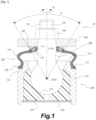
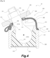
- FIGs. 1 and 4 are schematic cross-sectional views of the ball joint according to the embodiment of the present invention.
- Figs. 1 and 4 are cross-sectional views of the dust cover and other elements taken along a plane including a central axis of a shaft of a ball stud provided in the ball joint.
- the ball stud is in an upright state in Fig. 1
- the ball stud is in a maxim swung state in Fig. 4 .
- the ball joint 10 has a ball joint main body and a dust cover 100 attached to the ball joint main body.
- the ball joint main body has a ball stud 300, a socket 200 that supports the ball stud 300 in a rotatable and swingable manner, and a knuckle 400 as a coupling member that is coupled to the shaft 310 of the ball stud 300.
- the ball stud 300 has a spherical part 320 at one end of the shaft 310.
- the socket 200 has an annular case 210, a bottom plate 220 fixed to the bottom side of the case 210, and a bearing 230 for the spherical part 320.
- the bearing 230 has a bearing surface 231 which is a spherical surface having a radius equal to the radius of curvature of the spherical part 320.
- the knuckle 400 is coupled to the shaft 310 by a nut 500 on an opposite side to the spherical part 320 of the shaft 310.
- a threaded part 331 is provided on an outer peripheral surface of a tip end 330 of the shaft 310, and the nut 500 is screwed onto the threaded part 331.
- the ball joint 10 having the above-described structure allows the ball stud 300 to rotate (as illustrated by an arrow Q in Fig. 1 ) and swing (as illustrated by an arrow P in Fig. 1 ) with respect to the socket 200.
- the ball joint 10 according to the embodiment is provided with the dust cover 100 to prevent water and dust from entering the joint part and to prevent grease from coming out of the joint part.
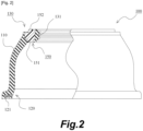
- Fig. 2 is a partially cutaway cross-sectional view of the dust cover 100 according to the embodiment of the present invention.
- Fig. 2 shows the dust cover 100 in a state in which no external force acts on it. When no external force acts on the dust cover 100, the dust cover 100 has a substantially rotationally symmetric shape.
- Fig. 2 shows, in the left part, a crosssection of the dust cover 100 taken along a plane including the central axis of the dust cover 100 with no external force acting on the dust cover 100.
- Figs. 3A and 3B are schematic views of a reinforcement ring according to the embodiment of the present invention.
- Fig. 3A is a bottom view of the reinforcement ring and
- Fig. 3B is a cross-sectional view taken along A-A line in Fig. 3A .
- the dust cover 100 includes a deformable film-like body part 110, a fixed part 120 provided on one end side of the body part 110 and fixed to the socket 200, and a seal part 130 provided on the other side of the body part 110.
- the body part 110 is shaped to have a middle part outwardly expanded.
- the dust cover 100 is largely made of an elastic body such as rubber. More specifically, the dust cover is made of an elastic material except for reinforcement rings 121 and 150 respectively embedded in the fixed part 120 and the seal part 130. In other words, the body part 110, the fixed part 120, and the seal part 130 are provided integrally except for the reinforcement rings 121 and 150.
- the reinforcement ring 121 is embedded in the elastic body part at the fixed part 120, so that the fixed part 120 is fitted into an annular notch 211 formed at a tip end of the case 210 of the socket 200 and fixed therein (as illustrated in Fig. 1 ).
- the reinforcement ring 121 is made of a material with high rigidity such as a metal.
- the seal part 130 having an elastic body part is integrally provided with other parts including the body part 110 as described above.
- An inner peripheral surface of the elastic body part is formed by an inner peripheral seal part 131 which is configured to slide on an outer peripheral surface of the shaft 310 of the ball stud 300.
- the inner peripheral seal part 131 according to the embodiment includes a plurality of annular protrusions.
- the reinforcement ring 150 is embedded in the elastic body part of the seal part 130 as described above.
- the reinforcement ring 150 is made of an annular member.
- the reinforcement ring 150 is made of a material with higher rigidity than the elastic body part such as nylon resin.
- a plurality of cylindrical protrusions 151 are provided on a bottom side of the reinforcement ring 150. According to the embodiment, the plurality of protrusions 151 are provided at equal intervals, but the protrusions do not necessarily need to be provided at equal intervals.
- a hollow cylindrical protrusion 152 is provided on an upper surface side of the reinforcement ring 150. When the reinforcement ring 150 is embedded in the elastic body part, tip end surfaces of the plurality of protrusions 151 and a tip end surface of the cylindrical protrusion 152 are exposed from the elastic body part.
- the dust cover 100 may be obtained for example by molding the elastic body part by insert molding using the reinforcement rings 121 and 150 as insert parts.
- the reinforcement ring 150 according to the embodiment has the plurality of protrusions 151 on a bottom surface side (the socket 200 side) and the hollow cylindrical protrusion 152 on a top surface side (the knuckle 400 side).
- the reinforcement ring may have a hollow cylindrical protrusion on the bottom surface side and a plurality of protrusions on the upper surface side, or the reinforcement ring may have a plurality of protrusions on both surface sides.
- the advantage of using the structure of the reinforcement ring 150 according to the embodiment is that the need for an element such as a positioning pin for positioning the reinforcement ring 150 is eliminated and a cost can be reduced.
- the tip end surface of the reinforcement ring 150 on the knuckle 400 side is in contact with the knuckle 400. More specifically, the tip end surface of the reinforcement ring 150 on the knuckle 400 side (the tip end surface of the protrusion 152) is exposed in a whole circumference (entire periphery), and the exposed part is configured to be in contact with the knuckle 400.
- the inner peripheral seal part 131 is provided on the inner peripheral surface side with respect to an area in which the reinforcement ring 150 and the knuckle 400 are in contact with each other (as illustrated in Figs. 1 and 4 ).
- At least a part of the tip end surface of the reinforcement ring 150 on the socket 200 side (corresponding to the tip end surface parts of the plurality of protrusions 151) is exposed from the elastic body part.
- the exposed part of the tip end surface of the reinforcement ring 150 on the socket 200 side abuts against an upper end surface 212 of the socket 200, so that the swinging range of the ball stud 300 is restricted (as illustrated in Fig. 4 ).
- the tip end surface of the reinforcement ring 150 on the knuckle 400 side is exposed from the elastic body part and in contact with the knuckle 400. This allows a positional relation between the reinforcement ring 150 and the knuckle 400 to be kept regardless of the movement of the ball stud 300. This prevents a part of the elastic body part from being caught between the reinforcement ring 150 and the knuckle 400.
- At least a part of the tip end surface of the reinforcement ring 150 on the socket 200 side (corresponding to the tip end surface parts of the plurality of protrusions 151) is exposed from the elastic body part.
- the exposed part of the tip end surface of the reinforcement ring 150 on the socket 200 side abuts against the upper end surface 212 of the socket 200, which restricts the swinging range of the ball stud 300. This prevents a part of the elastic body part from being caught between the reinforcement ring 150 and the socket 200.
Landscapes
- Engineering & Computer Science (AREA)
- General Engineering & Computer Science (AREA)
- Mechanical Engineering (AREA)
- Pivots And Pivotal Connections (AREA)
- Sealing Devices (AREA)
Applications Claiming Priority (2)
| Application Number | Priority Date | Filing Date | Title |
|---|---|---|---|
| JP2020075859 | 2020-04-22 | ||
| PCT/JP2021/015737 WO2021215363A1 (fr) | 2020-04-22 | 2021-04-16 | Joint à rotule et couvercle anti-poussière |
Publications (1)
| Publication Number | Publication Date |
|---|---|
| EP4141272A1 true EP4141272A1 (fr) | 2023-03-01 |
Family
ID=78269264
Family Applications (1)
| Application Number | Title | Priority Date | Filing Date |
|---|---|---|---|
| EP21792325.9A Withdrawn EP4141272A1 (fr) | 2020-04-22 | 2021-04-16 | Joint à rotule et couvercle anti-poussière |
Country Status (5)
| Country | Link |
|---|---|
| US (1) | US20230102909A1 (fr) |
| EP (1) | EP4141272A1 (fr) |
| JP (1) | JPWO2021215363A1 (fr) |
| CN (1) | CN115038882A (fr) |
| WO (1) | WO2021215363A1 (fr) |
Family Cites Families (6)
| Publication number | Priority date | Publication date | Assignee | Title |
|---|---|---|---|---|
| JPS6113067U (ja) * | 1984-06-28 | 1986-01-25 | エヌオーケー株式会社 | ダストカバ |
| JPS61157753U (fr) * | 1985-03-23 | 1986-09-30 | ||
| US5927891A (en) * | 1997-08-28 | 1999-07-27 | Trw Inc. | Boot seal for a ball and socket joint |
| JP2014219045A (ja) * | 2013-05-08 | 2014-11-20 | Nok株式会社 | ボールジョイント用ダストカバー |
| JP6176588B2 (ja) * | 2013-05-28 | 2017-08-09 | Nok株式会社 | ボールジョイント用ダストカバー |
| JP6711581B2 (ja) | 2015-10-07 | 2020-06-17 | Thkリズム株式会社 | ボールジョイント |
-
2021
- 2021-04-16 US US17/798,599 patent/US20230102909A1/en active Pending
- 2021-04-16 WO PCT/JP2021/015737 patent/WO2021215363A1/fr unknown
- 2021-04-16 JP JP2022517017A patent/JPWO2021215363A1/ja active Pending
- 2021-04-16 EP EP21792325.9A patent/EP4141272A1/fr not_active Withdrawn
- 2021-04-16 CN CN202180010989.2A patent/CN115038882A/zh active Pending
Also Published As
| Publication number | Publication date |
|---|---|
| CN115038882A (zh) | 2022-09-09 |
| US20230102909A1 (en) | 2023-03-30 |
| JPWO2021215363A1 (fr) | 2021-10-28 |
| WO2021215363A1 (fr) | 2021-10-28 |
Similar Documents
| Publication | Publication Date | Title |
|---|---|---|
| US6834863B2 (en) | Ball joint seal | |
| US7344311B2 (en) | Suspension joint bearing | |
| CN108368870B (zh) | 防尘罩以及密封构造 | |
| US11867225B2 (en) | Pivot joint assembly | |
| CN102575706A (zh) | 球窝接头 | |
| CN102410302A (zh) | 球接头 | |
| EP3428463A1 (fr) | Capot anti-poussière et structure d'étanchéité | |
| CN108138835B (zh) | 防尘罩 | |
| EP4141272A1 (fr) | Joint à rotule et couvercle anti-poussière | |
| US10718372B2 (en) | Dust boot for a moveable joint | |
| US20190345975A1 (en) | Ball Joint With Locking Ball Socket Assembly | |
| CN111373166A (zh) | 防尘罩 | |
| CN208236888U (zh) | 防尘罩 | |
| US20060159375A1 (en) | Inverted ball joint | |
| US11739791B2 (en) | Ball joint and dust cover | |
| EP3686447B1 (fr) | Joint à rotule et capot anti-poussière | |
| EP3686448B1 (fr) | Joint à rotule | |
| JPS6353309A (ja) | ワイパリンク用ボ−ルジヨイント装置 |
Legal Events
| Date | Code | Title | Description |
|---|---|---|---|
| STAA | Information on the status of an ep patent application or granted ep patent |
Free format text: STATUS: THE INTERNATIONAL PUBLICATION HAS BEEN MADE |
|
| PUAI | Public reference made under article 153(3) epc to a published international application that has entered the european phase |
Free format text: ORIGINAL CODE: 0009012 |
|
| STAA | Information on the status of an ep patent application or granted ep patent |
Free format text: STATUS: REQUEST FOR EXAMINATION WAS MADE |
|
| 17P | Request for examination filed |
Effective date: 20220808 |
|
| AK | Designated contracting states |
Kind code of ref document: A1 Designated state(s): AL AT BE BG CH CY CZ DE DK EE ES FI FR GB GR HR HU IE IS IT LI LT LU LV MC MK MT NL NO PL PT RO RS SE SI SK SM TR |
|
| DAV | Request for validation of the european patent (deleted) | ||
| DAX | Request for extension of the european patent (deleted) | ||
| STAA | Information on the status of an ep patent application or granted ep patent |
Free format text: STATUS: THE APPLICATION HAS BEEN WITHDRAWN |
|
| 18W | Application withdrawn |
Effective date: 20230926 |