EP4141149A1 - Filtration mechanism, and apparatus for producing conductive material - Google Patents
Filtration mechanism, and apparatus for producing conductive material Download PDFInfo
- Publication number
- EP4141149A1 EP4141149A1 EP21932775.6A EP21932775A EP4141149A1 EP 4141149 A1 EP4141149 A1 EP 4141149A1 EP 21932775 A EP21932775 A EP 21932775A EP 4141149 A1 EP4141149 A1 EP 4141149A1
- Authority
- EP
- European Patent Office
- Prior art keywords
- cover
- filtering
- supporting member
- filtering body
- conductive material
- Prior art date
- Legal status (The legal status is an assumption and is not a legal conclusion. Google has not performed a legal analysis and makes no representation as to the accuracy of the status listed.)
- Pending
Links
- 238000001914 filtration Methods 0.000 title claims abstract description 140
- 239000004020 conductor Substances 0.000 title claims abstract description 55
- 230000007246 mechanism Effects 0.000 title claims abstract description 48
- 238000009713 electroplating Methods 0.000 claims abstract description 49
- 239000000463 material Substances 0.000 claims abstract description 35
- 238000004519 manufacturing process Methods 0.000 abstract description 12
- 238000006748 scratching Methods 0.000 abstract description 8
- 230000002393 scratching effect Effects 0.000 abstract description 8
- 229910052751 metal Inorganic materials 0.000 description 10
- 239000002184 metal Substances 0.000 description 10
- 230000000694 effects Effects 0.000 description 8
- 238000005868 electrolysis reaction Methods 0.000 description 7
- 238000010586 diagram Methods 0.000 description 6
- 239000003792 electrolyte Substances 0.000 description 5
- 230000005484 gravity Effects 0.000 description 5
- 238000000034 method Methods 0.000 description 5
- 230000008569 process Effects 0.000 description 5
- 239000012535 impurity Substances 0.000 description 4
- 238000005260 corrosion Methods 0.000 description 3
- 230000007797 corrosion Effects 0.000 description 3
- 230000005611 electricity Effects 0.000 description 3
- 230000001788 irregular Effects 0.000 description 3
- 230000009471 action Effects 0.000 description 2
- 230000000712 assembly Effects 0.000 description 2
- 238000000429 assembly Methods 0.000 description 2
- 239000011888 foil Substances 0.000 description 2
- 238000009434 installation Methods 0.000 description 2
- BASFCYQUMIYNBI-UHFFFAOYSA-N platinum Chemical compound [Pt] BASFCYQUMIYNBI-UHFFFAOYSA-N 0.000 description 2
- RYGMFSIKBFXOCR-UHFFFAOYSA-N Copper Chemical compound [Cu] RYGMFSIKBFXOCR-UHFFFAOYSA-N 0.000 description 1
- HBBGRARXTFLTSG-UHFFFAOYSA-N Lithium ion Chemical compound [Li+] HBBGRARXTFLTSG-UHFFFAOYSA-N 0.000 description 1
- RTAQQCXQSZGOHL-UHFFFAOYSA-N Titanium Chemical compound [Ti] RTAQQCXQSZGOHL-UHFFFAOYSA-N 0.000 description 1
- 229910052782 aluminium Inorganic materials 0.000 description 1
- XAGFODPZIPBFFR-UHFFFAOYSA-N aluminium Chemical compound [Al] XAGFODPZIPBFFR-UHFFFAOYSA-N 0.000 description 1
- 238000010276 construction Methods 0.000 description 1
- 239000011889 copper foil Substances 0.000 description 1
- 238000007689 inspection Methods 0.000 description 1
- 229910001416 lithium ion Inorganic materials 0.000 description 1
- 238000012986 modification Methods 0.000 description 1
- 230000004048 modification Effects 0.000 description 1
- 239000004745 nonwoven fabric Substances 0.000 description 1
- 229910052697 platinum Inorganic materials 0.000 description 1
- 239000007779 soft material Substances 0.000 description 1
- 229910052719 titanium Inorganic materials 0.000 description 1
- 239000010936 titanium Substances 0.000 description 1
- 230000009466 transformation Effects 0.000 description 1
- 238000000844 transformation Methods 0.000 description 1
Images



Classifications
-
- C—CHEMISTRY; METALLURGY
- C25—ELECTROLYTIC OR ELECTROPHORETIC PROCESSES; APPARATUS THEREFOR
- C25D—PROCESSES FOR THE ELECTROLYTIC OR ELECTROPHORETIC PRODUCTION OF COATINGS; ELECTROFORMING; APPARATUS THEREFOR
- C25D7/00—Electroplating characterised by the article coated
- C25D7/06—Wires; Strips; Foils
- C25D7/0614—Strips or foils
-
- C—CHEMISTRY; METALLURGY
- C25—ELECTROLYTIC OR ELECTROPHORETIC PROCESSES; APPARATUS THEREFOR
- C25D—PROCESSES FOR THE ELECTROLYTIC OR ELECTROPHORETIC PRODUCTION OF COATINGS; ELECTROFORMING; APPARATUS THEREFOR
- C25D21/00—Processes for servicing or operating cells for electrolytic coating
- C25D21/06—Filtering particles other than ions
-
- C—CHEMISTRY; METALLURGY
- C25—ELECTROLYTIC OR ELECTROPHORETIC PROCESSES; APPARATUS THEREFOR
- C25D—PROCESSES FOR THE ELECTROLYTIC OR ELECTROPHORETIC PRODUCTION OF COATINGS; ELECTROFORMING; APPARATUS THEREFOR
- C25D17/00—Constructional parts, or assemblies thereof, of cells for electrolytic coating
-
- C—CHEMISTRY; METALLURGY
- C25—ELECTROLYTIC OR ELECTROPHORETIC PROCESSES; APPARATUS THEREFOR
- C25D—PROCESSES FOR THE ELECTROLYTIC OR ELECTROPHORETIC PRODUCTION OF COATINGS; ELECTROFORMING; APPARATUS THEREFOR
- C25D17/00—Constructional parts, or assemblies thereof, of cells for electrolytic coating
- C25D17/10—Electrodes, e.g. composition, counter electrode
-
- C—CHEMISTRY; METALLURGY
- C25—ELECTROLYTIC OR ELECTROPHORETIC PROCESSES; APPARATUS THEREFOR
- C25D—PROCESSES FOR THE ELECTROLYTIC OR ELECTROPHORETIC PRODUCTION OF COATINGS; ELECTROFORMING; APPARATUS THEREFOR
- C25D17/00—Constructional parts, or assemblies thereof, of cells for electrolytic coating
- C25D17/10—Electrodes, e.g. composition, counter electrode
- C25D17/12—Shape or form
-
- C—CHEMISTRY; METALLURGY
- C25—ELECTROLYTIC OR ELECTROPHORETIC PROCESSES; APPARATUS THEREFOR
- C25D—PROCESSES FOR THE ELECTROLYTIC OR ELECTROPHORETIC PRODUCTION OF COATINGS; ELECTROFORMING; APPARATUS THEREFOR
- C25D7/00—Electroplating characterised by the article coated
- C25D7/06—Wires; Strips; Foils
-
- H—ELECTRICITY
- H01—ELECTRIC ELEMENTS
- H01M—PROCESSES OR MEANS, e.g. BATTERIES, FOR THE DIRECT CONVERSION OF CHEMICAL ENERGY INTO ELECTRICAL ENERGY
- H01M10/00—Secondary cells; Manufacture thereof
- H01M10/05—Accumulators with non-aqueous electrolyte
- H01M10/052—Li-accumulators
- H01M10/0525—Rocking-chair batteries, i.e. batteries with lithium insertion or intercalation in both electrodes; Lithium-ion batteries
Definitions
- This application relates to the technical field of battery production, and in particular, to a filtering mechanism and a device for producing a conductive material.
- an electroplating material needs to be electroplated onto a surface of the conductive material. Specifically, soluble metal is electroplated onto the conductive material. However, during electrolysis, the conductive material is often scratched.
- a filtering mechanism and a device for producing a conductive material need to be provided to resolve a technical problem that conductive materials are often scratched during electrolysis in the prior art.
- the inventors proposed a filtering mechanism for producing a conductive material, where the filtering mechanism includes:
- the supporting member is provided on the cover to enhance connection strength between the cover and the filtering body.
- the cover of the filtering mechanism can be effectively prevented from curling, and the cover can be prevented from scratching the conductive material, thereby improving a production yield rate and production efficiency of conductive materials.
- the opening is located at the top of the filtering body
- the cover includes a top cover and a side cover, the top cover being provided at the top of the filtering body to cover the opening, the side cover being connected to the top cover and provided on a side of the filtering body, and the side cover being provided with the supporting member.
- the top cover covers the opening, the side cover is connected to the top cover, and the side cover is provided with the supporting member; and the side cover can pull the top cover downward in the direction of gravity under an action of gravity of the supporting member, thereby preventing the top cover and the side cover from curling upward and scratching the conductive material.
- a cavity for accommodating the supporting member is provided in the side cover.
- a cavity for accommodating the supporting member is provided in the side cover, and the supporting member can be directly placed in the cavity to facilitate installation and detachment of the supporting member.
- the cover has two opposite ends, one end being movably connected to the filtering body, and the other end being provided with the supporting member.
- one end of the cover is movably connected to the filtering body, and the other end is provided with the supporting member to pull the entire cover downward to effectively prevent the cover from curling.
- the supporting member extends in a length direction of the opening, and the cover is provided with the supporting member in the length direction of the opening.
- the cover is provided with the supporting member in the length direction of the opening to prevent any part of the cover in the length direction of the opening from curling.
- the end of the cover that is provided with the supporting member is connected to the filtering body via a hook-and-loop fastener.
- the cover may be fastened to the filtering body via the hook-and-loop fastener.
- another fastening structure is added, which can further prevent the cover from curling.
- the hook-and-loop fastener includes a hook tape and a loop tape
- the supporting member is provided outside a bonding surface of the hook tape and the loop tape to support the bonding surface, so that connection strength between the hook tape and the loop tape is enhanced.
- the supporting member is provided outside the bonding surface of the hook tape and the loop tape, which can support the bonding surface, improve an overall bonding effect of the hook-and-loop fastener, and ensure tight attachment of the hook-and-loop fastener, high pasting flatness, and even force on the bonding surface, so that the connection strength between the hook tape and the loop tape is enhanced and the cover is not likely to curl.
- the filtering mechanism further includes a fastening assembly, and the side cover is connected to the filtering body via the fastening assembly.
- the fastening assembly is further provided for double insurance. Even if the cover and the filtering body are partially detached, the fastening assembly can still ensure that the cover cannot curl or scratch the conductive material.
- the filtering mechanism further includes a conductive body, the electroplating material is provided in the conductive body, and the filtering body and the cover are configured to cover the conductive body.
- the electroplating material in a process of forming an electroplating layer on the conductive material, the electroplating material needs to be energized.
- directly energizing the electroplating material cannot implement a good energization effect. Therefore, the electroplating material is provided in the conductive body, the conductive body is insoluble metal that is resistant to electricity and corrosion, and the conductive body is energized, so that the electrolysis effect can be effectively improved.
- the inventors further proposed a device for producing a conductive material, including the filtering mechanism according to any one of the foregoing embodiments.
- the cover of the filtering mechanism can be effectively prevented from curling, and the cover can be prevented from scratching the conductive material, thereby improving a production yield rate and production efficiency of conductive materials.
- filtering mechanism 11. filtering body, 111. accommodating cavity, 112. opening, 12. cover, 121. top cover, 122. side cover, 1221. cavity, 13. supporting member, 14. hook-and-loop fastener, 141. hook tape, 142. loop tape, 15. fastening assembly, 151. connection member, 152. fastening point, 16. conductive body, 2. electroplating material, 3. guide wheel, 4. anode wire, 5. cathode wire, 6. cathode conductive apparatus, 7. power supply, and 8. conductive material.
- connection may be a fixed connection, a detachable connection, an integrated connection, or an electrical connection; or may be a direct connection, or an indirect connection through an intermediate medium. Persons of ordinary skill in the art can understand specific meanings of these terms in the embodiments based on specific situations.
- the inventors usually found that a surface of an electroplated conductive material 8 is scratched, and electroplating needs to be stopped for inspection. At first, the inventors thought that the scratch is caused by a guide wheel 3, but after the guide wheel 3 has been improved, the surface of the conductive material 8 is still scratched. After further research, the inventors found that the surface of the conductive material 8 is scratched because a filtering mechanism 1 is eroded in an electrolyte, and the filtering mechanism 1 curls in a direction indicated by an arrow z in the figure to scratch the conductive material 8. In addition, to avoid a problem that the conductive material 8 cannot be used because the conductive material 8 is scratched when the filtering mechanism 1 curls, this application provides a device for producing a conductive material.
- a direction indicated by an arrow x in the figure is a length direction of an opening 112 of a filtering body 11
- a direction indicated by an arrow y in the figure is a width direction of the opening 112 of the filtering body 11
- a direction indicated by an arrow z in the figure is a height direction of the filtering body 11.
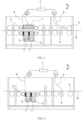
- this embodiment relates to a device for producing a conductive material, and the device includes a filtering mechanism 1, an electroplating material 2, guide wheels 3, an anode wire 4, a cathode wire 5, a cathode conductive apparatus 6, a power supply 7, and a conductive material 8.
- the electroplating material 2 is soluble metal, and the soluble metal is attached to the conductive material 8 after electrolysis.
- the soluble metal includes impurities, if the impurities enter the electrolyte, quality of electroplating is easily affected.
- the filtering mechanism 1 fits around the electroplating material 2, so that the filtering mechanism 1 can filter the electroplating material 2 when the electroplating material 2 is electrolyzed to keep, within the filtering mechanism 1, impurities generated during the electrolysis of the electroplating material 2.
- the conductive material 8 passes through an electroplating device by using the guide wheels 3 provided at front and rear ends of the electroplating device, a positive electrode of the power supply 7 is electrically connected to the electroplating material 2 via the anode wire 4, and a negative electrode of the power supply 7 is electrically connected to the cathode conductive apparatus 6 via the cathode wire 5, so as to form a complete loop; and after power-on of the power supply 7, electroplating can be implemented.
- electroplating as long as the guide wheels 3 are driven to rotate, the conductive material 8 can be controlled to move forward.
- a roller of the guide wheel 3 is made of a soft material such as rubber or plastic, and a buffer layer may also be provided on the roller of the guide wheel 3 to protect the conductive material 8.
- both surfaces of the conductive material 8 may be plated simultaneously; or alternatively, as shown in FIG. 2 , a single surface of the conductive material 8 may be plated, which both fall within the protection scope of the embodiments.
- the conductive material 8 is a current collector of a battery, and mainly refers to metal foil such as copper foil or aluminum foil in a lithium-ion battery, or may alternatively refer to a tab generally. Therefore, in this embodiment, the device is mainly an electroplating device for producing a current collector of a battery. However, in other embodiments, the device may also be used to produce another conductive material 8, for example, a conductive material 8 for an electrical product such as a motor, a cable, or an electrical instrument, which also falls within the protection scope of the embodiments. As shown in FIG. 3 to FIG. 6 , an embodiment further relates to a filtering mechanism 1.
- the filtering mechanism 1 includes a filtering body 11, a cover 12, and a supporting member 13.
- the filtering body 11 includes an accommodating cavity 111 for accommodating an electroplating material and an opening 112 provided on the filtering body 11.
- the cover 12 is configured to cover the opening 112 and be connected to the filtering body 11 to enclose the electroplating material 2 in the filtering body 11.
- the supporting member 13 is provided on the cover 12 to enhance connection strength between the cover 12 and the filtering body 11. The supporting member 13 is provided, so that the filtering mechanism 1 can be effectively prevented from curling, improving a production yield rate and production efficiency of the conductive material 8.
- the filtering body 11 has a cuboid structure
- the corresponding opening 112 of the filtering body 11 has a rectangular structure
- the cover 12 is a rectangular cover 12.
- the filtering body 11 may have a cylindrical structure, an inverted cone structure, another irregular structure, or the like, and the corresponding opening 112 of the filtering body 11 has a circular structure or an irregular structure, which all fall within the protection scope of the embodiments.
- the filtering body 11 includes the accommodating cavity 111 for accommodating the electroplating material 2 and the opening 112 provided on the filtering body 11, an end of the cover 12 is connected to the filtering body 11, and the cover 12 covers the opening 112 to enclose the electroplating material 2 in the filtering body 11; and the supporting member 13 is provided on the cover 12, and the cover 12 covers the opening 112 of the filtering body 11 to prevent the cover 12 from curling in the direction indicated by the arrow z in the figure and effectively, effectively preventing the cover 12 from scratching the conductive material, and thereby improving a production yield rate of the conductive material.
- the cover 12 includes a top cover 121 and a side cover 122, the top cover 121 is provided on the top of the filtering body 11 to cover the opening 112, the side cover 122 is connected to the top cover 121 and provided on a side of the filtering body 11, and the side cover 122 is provided with the supporting member 13.
- the supporting member 13 is provided in the side cover 122; and the side cover 122 can pull the top cover 121 downward in the direction of gravity under an action of gravity of the supporting member 13, thereby preventing the top cover 121 and the side cover 122 from curling in the direction indicated by the arrow z in the figure and scratching the conductive material.
- a structure of the cover 12 may be an integrated structure, and the supporting member 13 is provided on the cover 12 to fasten the entire cover 12 onto the filtering body 11.
- the cover 12 may alternatively be divided into discrete structures, where a first part is provided on the top of the filtering body 11, such as the top cover 121; and a second part is provided on a side of the filtering body 11, such as the side cover 122, and the side cover 122 is connected to the top cover 121.
- the supporting member 13 may be provided only on the side cover 122 to be connected to the top cover 121 via the side cover 122 to pull the top cover 121 downward in the direction of gravity; or the supporting members 13 may be provided in both the side cover 122 and the top cover 121 to fasten the cover 12 onto the filtering body 11, effectively preventing the cover 12 from curling in the direction indicated by the arrow z in the figure.
- the foregoing two implementations of the cover 12 all fall within the protection scope of the embodiments.
- the cover 12 has a discrete rectangular structure, a top end of the side cover 122 is hinged with the top cover 121, and the cover 12 has two opposite ends, one end being movably connected to the filtering body 11, and the other end being provided with the supporting member 13.
- One end of the cover 12 is movably connected to the filtering body 11 to facilitate opening of the cover 12; and the other end of the cover 12 is provided with the supporting member 13 to pull the entire cover 12 downward to effectively prevent the cover 12 from curling.
- the supporting member 13 has a long plate structure, a shape of the supporting member 13 matches the rectangular shape of the side cover 122, and therefore, the supporting member 13 can be provided inside the side cover 122.
- the supporting member 13 may have a segmented structure or another long plate structure; and the supporting member 13 may alternatively be directly provided outside the side cover 122, and the side cover 122 may be directly pressed against a side wall of the filtering body 11, which all fall within the protection scope of the embodiments.
- the supporting member 13 extends in a length direction (a direction indicated by the arrow x in the figure) of the opening 112, and the cover 12 is provided with the supporting member 13 in the length direction (the direction indicated by the arrow x in the figure) of the opening 112.
- the cover 12 is provided with the supporting member 13 in the length direction (the direction indicated by the arrow x in the figure) of the opening 112 to prevent any part of the cover 12 from curling in the length direction of the opening 112 (the direction indicated by the arrow x in the figure).
- the filtering mechanism further includes a fastening assembly 15.
- the cover 12 may be connected to the filtering body 11 via the fastening assembly 15 for double insurance. Even if the cover 12 and the filtering body 11 are partially detached, the fastening assembly 15 may still ensure that the cover 12 cannot curl in the direction indicated by the arrow z in the figure or scratch the conductive material 8.
- the filtering mechanism 1 includes more than two fastening assemblies 15, and the more than two fastening assemblies 15 are arranged in the length direction of the opening 112 of the filtering body 11 (the direction indicated by the arrow x in the figure). The connection strength between the cover 12 and the filtering body 11 is further enhanced.
- the fastening assembly 15 in this embodiment includes a connection member 151 and a fastening point 152, where the connection member 151 is provided on the side cover 122, and the fastening point 152 is provided on the filtering body 11, with the connection member 151 and the fastening point 152 detachably connected.
- the connection member 151 is provided at the bottom of the side cover 122
- the fastening point 152 is correspondingly provided at a relative position of the filtering body 11
- the side cover 122 matches the fastening point 152, so that the side cover 122 is connected to the filtering body 11.
- a plurality of connection members 151 are provided at the bottom of the side cover 122, and a plurality of fastening points 152 are also provided on a side wall of the filtering body 11.
- the cover 12 may alternatively be connected to the filtering body 11 via a hook-and-loop fastener 14. It can be understood that the end of the cover 12 that is provided with the supporting member 13 is connected to the filtering body 11 via the hook-and-loop fastener 14. The cover 12 may be fastened to the filtering body 11 via the hook-and-loop fastener 14. On the basis of the supporting member 13, another fastening structure is added, which can further prevent the cover 12 from curling.
- the cover 12 may be connected to the filtering body 11 in other detachable connection manners, such as non-metallic buckle connection or non-metallic screw connection, which all fall within the protection scope of the embodiments.
- the hook-and-loop fastener 14 includes a hook tape 141 and a loop tape 142, and the hook tape 141 matches the loop tape 142, so that the side cover 122 is fastened to the filtering body 11.
- the hook tape 141 is provided inside the side cover 122, and the loop tape 142 is provided on an outer surface of the filtering body 11; and in other embodiments, the hook tape 141 is provided on the outer surface of the filtering body 11, and the loop tape 142 is provided inside the side cover 122.
- the hook tape 141 matches the loop tape 142, so that the cover 12 is fastened to the filtering body 11.
- a cavity 1221 for accommodating the supporting member 13 is provided in the side cover 122, so that the supporting member 13 can be directly placed in the cavity 1221 to facilitate installation and detachment of the supporting member 13.
- the supporting member 13 may be provided outside the side cover 122 to press the side cover 122 toward the filtering body 11, which also falls within the protection scope of the embodiments.
- the supporting member 13 may alternatively be provided outside a bonding surface of the hook tape 141 and the loop tape 142 to support the bonding surface of the hook tape 141 and the loop tape 142, so that connection strength between the hook tape 141 and the loop tape 142 is enhanced.
- the supporting member 13 is provided outside the bonding surface of the hook tape 141 and the loop tape 142, which can improve an overall bonding effect of the hook-and-loop fastener 14, and ensure tight attachment of the hook-and-loop fastener 14, high pasting flatness, and even force on the bonding surface, so that the connection strength between the hook tape 141 and the loop tape 142 is enhanced and the side cover 122 is not likely to curl in the direction indicated by the arrow z in the figure.
- the filtering mechanism 1 in this embodiment of this application may further include a conductive body 16.
- the conductive body 16 is insoluble metal that is resistant to electricity and corrosion, and the conductive body 16 is specifically titanium, platinum, or the like. When the conductive body 16 is energized, the electroplating material 2 can be indirectly energized.
- the conductive body 16 is insoluble metal that is resistant to electricity and corrosion, compared with a manner of directly energizing the electroplating material 2, even if the electroplating material 2 in this application is slowly dissolved, the conductive body 16 can still have a good conductive effect, which can effectively improve an electrolysis effect and ensure effectiveness of electroplating.
- the conductive body 16 has a cuboid structure
- the filtering body 11 and the cover 12 are made of non-woven fabric
- the filtering body 11 and the cover 12 fit around an outer surface of the conductive body 16.
- the electroplating material 2 is provided in the conductive body 16
- the filtering body 11 and the cover 12 are configured to cover the conductive body 16
- the power supply 7 is configured to energize the conductive body 16.
- the conductive body 16 may have a cylindrical structure, an inverted cone structure, another irregular structure, or the like, and the filtering body 11 and the cover 12 may be adjusted along with adjustment of the shape of the conductive body 16, which all fall within the protection scope of the embodiments.
- a plurality of electroplating materials 2 are put into the conductive body 16, and the conductive body 16 is fitted around the filtering body 11 and then covered with the cover 12; the hook tape 141 matches the loop tape 142, so that the side cover 122 of the cover 12 is fastened to the filtering body 11; and the side cover 122 is fastened to the filtering body 11 via the fastening assembly 15 to form the filtering mechanism 1.
- the filtering mechanism 1 is put into an electrolyte, a positive electrode of the power supply 7 is electrically connected to the electroplating material 2 via an anode wire 4, and a negative electrode of the power supply 7 is electrically connected to the cathode conductive apparatus 6 via a cathode wire 5.
- the power supply 7 is powered on for electroplating of the conductive material 8; and after the electroplating, the filtering mechanism 1 is taken out of the electrolyte, the fastening assembly 15, the hook tape 141, and the loop tape 142 are unfastened, the filtering body 11 and the cover 12 are replaced, and after the electroplating material 2 is put in again, the electroplating can be restarted.
- the cover 12 of the filtering mechanism 1 can be effectively prevented from curling in the direction indicated by the arrow z in the figure, and the cover 12 can be effectively prevented from scratching the conductive material 8, thereby improving a production yield rate of the conductive material 8.
Landscapes
- Chemical & Material Sciences (AREA)
- Engineering & Computer Science (AREA)
- Chemical Kinetics & Catalysis (AREA)
- Electrochemistry (AREA)
- Materials Engineering (AREA)
- Metallurgy (AREA)
- Organic Chemistry (AREA)
- Electroplating Methods And Accessories (AREA)
- Filtration Of Liquid (AREA)
- Cell Electrode Carriers And Collectors (AREA)
- Filtering Materials (AREA)
Abstract
Description
- This application claims priority to
Chinese patent application No. 202120611024.6, filed on March 25, 2021 - This application relates to the technical field of battery production, and in particular, to a filtering mechanism and a device for producing a conductive material.
- During production of a conductive material, an electroplating material needs to be electroplated onto a surface of the conductive material. Specifically, soluble metal is electroplated onto the conductive material. However, during electrolysis, the conductive material is often scratched.
- In view of this, a filtering mechanism and a device for producing a conductive material need to be provided to resolve a technical problem that conductive materials are often scratched during electrolysis in the prior art.
- To achieve the foregoing objective, the inventors proposed a filtering mechanism for producing a conductive material, where the filtering mechanism includes:
- a filtering body, including an accommodating cavity for accommodating an electroplating material and an opening provided on the filtering body;
- a cover, configured to cover the opening and connect to the filtering body to enclose the electroplating material in the filtering body; and
- a supporting member, provided on the cover to enhance connection strength between the cover and the filtering body.
- Different from the prior art, in the technical solutions of this application, the supporting member is provided on the cover to enhance connection strength between the cover and the filtering body. In this way, the cover of the filtering mechanism can be effectively prevented from curling, and the cover can be prevented from scratching the conductive material, thereby improving a production yield rate and production efficiency of conductive materials.
- In an embodiment of this application, the opening is located at the top of the filtering body, and the cover includes a top cover and a side cover, the top cover being provided at the top of the filtering body to cover the opening, the side cover being connected to the top cover and provided on a side of the filtering body, and the side cover being provided with the supporting member.
- In this way, the top cover covers the opening, the side cover is connected to the top cover, and the side cover is provided with the supporting member; and the side cover can pull the top cover downward in the direction of gravity under an action of gravity of the supporting member, thereby preventing the top cover and the side cover from curling upward and scratching the conductive material.
- In an embodiment of this application, a cavity for accommodating the supporting member is provided in the side cover.
- In this case, a cavity for accommodating the supporting member is provided in the side cover, and the supporting member can be directly placed in the cavity to facilitate installation and detachment of the supporting member.
- In an embodiment of this application, the cover has two opposite ends, one end being movably connected to the filtering body, and the other end being provided with the supporting member.
- In this case, to facilitate opening of the cover, one end of the cover is movably connected to the filtering body, and the other end is provided with the supporting member to pull the entire cover downward to effectively prevent the cover from curling.
- In an embodiment of this application, the supporting member extends in a length direction of the opening, and the cover is provided with the supporting member in the length direction of the opening.
- In this way, the cover is provided with the supporting member in the length direction of the opening to prevent any part of the cover in the length direction of the opening from curling.
- In an embodiment of this application, the end of the cover that is provided with the supporting member is connected to the filtering body via a hook-and-loop fastener.
- In this way, the cover may be fastened to the filtering body via the hook-and-loop fastener. On the basis of the supporting member, another fastening structure is added, which can further prevent the cover from curling.
- In an embodiment of this application, the hook-and-loop fastener includes a hook tape and a loop tape, and the supporting member is provided outside a bonding surface of the hook tape and the loop tape to support the bonding surface, so that connection strength between the hook tape and the loop tape is enhanced.
- In this way, the supporting member is provided outside the bonding surface of the hook tape and the loop tape, which can support the bonding surface, improve an overall bonding effect of the hook-and-loop fastener, and ensure tight attachment of the hook-and-loop fastener, high pasting flatness, and even force on the bonding surface, so that the connection strength between the hook tape and the loop tape is enhanced and the cover is not likely to curl.
- In an embodiment of this application, the filtering mechanism further includes a fastening assembly, and the side cover is connected to the filtering body via the fastening assembly.
- In the way, the fastening assembly is further provided for double insurance. Even if the cover and the filtering body are partially detached, the fastening assembly can still ensure that the cover cannot curl or scratch the conductive material.
- In an embodiment of this application, the filtering mechanism further includes a conductive body, the electroplating material is provided in the conductive body, and the filtering body and the cover are configured to cover the conductive body.
- In this case, in a process of forming an electroplating layer on the conductive material, the electroplating material needs to be energized. However, directly energizing the electroplating material cannot implement a good energization effect. Therefore, the electroplating material is provided in the conductive body, the conductive body is insoluble metal that is resistant to electricity and corrosion, and the conductive body is energized, so that the electrolysis effect can be effectively improved.
- To achieve the foregoing objective, the inventors further proposed a device for producing a conductive material, including the filtering mechanism according to any one of the foregoing embodiments.
- Different from the prior art, in the process of producing the conductive material in the technical solutions of this application, the cover of the filtering mechanism can be effectively prevented from curling, and the cover can be prevented from scratching the conductive material, thereby improving a production yield rate and production efficiency of conductive materials.
- In order to describe the technical solutions in the embodiments of this application more clearly, the following briefly describes the accompanying drawings required for describing the embodiments. It should be understood that, the accompanying drawings below only show some embodiments of this application, and thus should not be considered as a limitation on the scope. Persons of ordinary skill in the art may still derive other related drawings from the accompanying drawings without creative efforts.
-
FIG. 1 is a schematic structural diagram of a device for producing a battery according to a specific embodiment; -
FIG. 2 is another schematic diagram of a device for producing a battery according to a specific embodiment; -
FIG. 3 is a schematic structural diagram of a filtering mechanism according to a specific embodiment; -
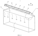
FIG. 4 is a schematic structural diagram of a filtering mechanism in an open state according to a specific embodiment; -
FIG. 5 is a schematic diagram of local enlargement of a location A inFIG. 4 ; and -
FIG. 6 is a schematic cross-sectional diagram of a filtering mechanism according to a specific embodiment. - The accompanying drawings are not drawn to scale.
- Reference signs: 1. filtering mechanism, 11. filtering body, 111. accommodating cavity, 112. opening, 12. cover, 121. top cover, 122. side cover, 1221. cavity, 13. supporting member, 14. hook-and-loop fastener, 141. hook tape, 142. loop tape, 15. fastening assembly, 151. connection member, 152. fastening point, 16. conductive body, 2. electroplating material, 3. guide wheel, 4. anode wire, 5. cathode wire, 6. cathode conductive apparatus, 7. power supply, and 8. conductive material.
- To explain technical content, construction features, and objectives and effects achieved of technical solutions in detail, the following describes in detail with reference to specific embodiments and accompanying drawings.
- In the descriptions of this application, unless otherwise specified and defined explicitly, the terms "first" and "second" are merely intended for a purpose of description, and should not be understood as any indication or implication of relative importance; unless otherwise specified and defined explicitly, the term "plurality of" indicates two or more; and the terms "connection" and "fastening" should be understood in their general senses. For example, the "connection" may be a fixed connection, a detachable connection, an integrated connection, or an electrical connection; or may be a direct connection, or an indirect connection through an intermediate medium. Persons of ordinary skill in the art can understand specific meanings of these terms in the embodiments based on specific situations.
- In the descriptions of this specification, it should be understood that the positional terms such as "up", "down", "left", and "right" described in the embodiments of this application are described from angles shown in the accompanying drawings, and should not be understood as a limitation on the embodiments of this application. In addition, in the context, it should be further understood that when an element is described as being "above" or "under" another element, that element may not only be directly connected "above" or "under" the another element, but also be indirectly connected "above" or "under" the another element through an intermediate element.
- During electroplating, the inventors usually found that a surface of an electroplated conductive material 8 is scratched, and electroplating needs to be stopped for inspection. At first, the inventors thought that the scratch is caused by a
guide wheel 3, but after theguide wheel 3 has been improved, the surface of the conductive material 8 is still scratched. After further research, the inventors found that the surface of the conductive material 8 is scratched because afiltering mechanism 1 is eroded in an electrolyte, and thefiltering mechanism 1 curls in a direction indicated by an arrow z in the figure to scratch the conductive material 8. In addition, to avoid a problem that the conductive material 8 cannot be used because the conductive material 8 is scratched when thefiltering mechanism 1 curls, this application provides a device for producing a conductive material. - The device for producing a conductive material provided in this application is described below with specific embodiments. A direction indicated by an arrow x in the figure is a length direction of an
opening 112 of afiltering body 11, a direction indicated by an arrow y in the figure is a width direction of theopening 112 of thefiltering body 11, and a direction indicated by an arrow z in the figure is a height direction of thefiltering body 11. Referring toFIG. 1 and FIG. 2 , this embodiment relates to a device for producing a conductive material, and the device includes afiltering mechanism 1, anelectroplating material 2, guidewheels 3, an anode wire 4, acathode wire 5, a cathodeconductive apparatus 6, a power supply 7, and a conductive material 8. In this embodiment, theelectroplating material 2 is soluble metal, and the soluble metal is attached to the conductive material 8 after electrolysis. As the soluble metal includes impurities, if the impurities enter the electrolyte, quality of electroplating is easily affected. To prevent the impurities in the soluble metal from entering the electrolyte during the electrolysis, in this embodiment, thefiltering mechanism 1 fits around theelectroplating material 2, so that thefiltering mechanism 1 can filter theelectroplating material 2 when theelectroplating material 2 is electrolyzed to keep, within thefiltering mechanism 1, impurities generated during the electrolysis of theelectroplating material 2. - In this embodiment, the conductive material 8 passes through an electroplating device by using the
guide wheels 3 provided at front and rear ends of the electroplating device, a positive electrode of the power supply 7 is electrically connected to theelectroplating material 2 via the anode wire 4, and a negative electrode of the power supply 7 is electrically connected to the cathodeconductive apparatus 6 via thecathode wire 5, so as to form a complete loop; and after power-on of the power supply 7, electroplating can be implemented. During electroplating, as long as theguide wheels 3 are driven to rotate, the conductive material 8 can be controlled to move forward. To prevent theguide wheels 3 from scratching the conductive material 8, a roller of theguide wheel 3 is made of a soft material such as rubber or plastic, and a buffer layer may also be provided on the roller of theguide wheel 3 to protect the conductive material 8. - As shown in
FIG. 1 , both surfaces of the conductive material 8 may be plated simultaneously; or alternatively, as shown inFIG. 2 , a single surface of the conductive material 8 may be plated, which both fall within the protection scope of the embodiments. - It should be noted that, in this embodiment, the conductive material 8 is a current collector of a battery, and mainly refers to metal foil such as copper foil or aluminum foil in a lithium-ion battery, or may alternatively refer to a tab generally. Therefore, in this embodiment, the device is mainly an electroplating device for producing a current collector of a battery. However, in other embodiments, the device may also be used to produce another conductive material 8, for example, a conductive material 8 for an electrical product such as a motor, a cable, or an electrical instrument, which also falls within the protection scope of the embodiments. As shown in
FIG. 3 to FIG. 6 , an embodiment further relates to afiltering mechanism 1. Thefiltering mechanism 1 includes afiltering body 11, acover 12, and a supportingmember 13. Thefiltering body 11 includes anaccommodating cavity 111 for accommodating an electroplating material and anopening 112 provided on thefiltering body 11. Thecover 12 is configured to cover theopening 112 and be connected to thefiltering body 11 to enclose theelectroplating material 2 in thefiltering body 11. The supportingmember 13 is provided on thecover 12 to enhance connection strength between thecover 12 and thefiltering body 11. The supportingmember 13 is provided, so that thefiltering mechanism 1 can be effectively prevented from curling, improving a production yield rate and production efficiency of the conductive material 8. In this embodiment, thefiltering body 11 has a cuboid structure, thecorresponding opening 112 of thefiltering body 11 has a rectangular structure, and thecover 12 is arectangular cover 12. In other embodiments, thefiltering body 11 may have a cylindrical structure, an inverted cone structure, another irregular structure, or the like, and thecorresponding opening 112 of thefiltering body 11 has a circular structure or an irregular structure, which all fall within the protection scope of the embodiments. - In this embodiment, the
filtering body 11 includes theaccommodating cavity 111 for accommodating theelectroplating material 2 and theopening 112 provided on thefiltering body 11, an end of thecover 12 is connected to thefiltering body 11, and thecover 12 covers theopening 112 to enclose theelectroplating material 2 in thefiltering body 11; and the supportingmember 13 is provided on thecover 12, and thecover 12 covers theopening 112 of thefiltering body 11 to prevent thecover 12 from curling in the direction indicated by the arrow z in the figure and effectively, effectively preventing thecover 12 from scratching the conductive material, and thereby improving a production yield rate of the conductive material. - Optionally, in this embodiment, the
cover 12 includes atop cover 121 and aside cover 122, thetop cover 121 is provided on the top of thefiltering body 11 to cover theopening 112, theside cover 122 is connected to thetop cover 121 and provided on a side of thefiltering body 11, and theside cover 122 is provided with the supportingmember 13. In addition, the supportingmember 13 is provided in theside cover 122; and theside cover 122 can pull thetop cover 121 downward in the direction of gravity under an action of gravity of the supportingmember 13, thereby preventing thetop cover 121 and theside cover 122 from curling in the direction indicated by the arrow z in the figure and scratching the conductive material. - It should be noted that a structure of the
cover 12 may be an integrated structure, and the supportingmember 13 is provided on thecover 12 to fasten theentire cover 12 onto thefiltering body 11. Thecover 12 may alternatively be divided into discrete structures, where a first part is provided on the top of thefiltering body 11, such as thetop cover 121; and a second part is provided on a side of thefiltering body 11, such as theside cover 122, and theside cover 122 is connected to thetop cover 121. The supportingmember 13 may be provided only on theside cover 122 to be connected to thetop cover 121 via theside cover 122 to pull thetop cover 121 downward in the direction of gravity; or the supportingmembers 13 may be provided in both theside cover 122 and thetop cover 121 to fasten thecover 12 onto thefiltering body 11, effectively preventing thecover 12 from curling in the direction indicated by the arrow z in the figure. The foregoing two implementations of thecover 12 all fall within the protection scope of the embodiments. - In this embodiment, the
cover 12 has a discrete rectangular structure, a top end of theside cover 122 is hinged with thetop cover 121, and thecover 12 has two opposite ends, one end being movably connected to thefiltering body 11, and the other end being provided with the supportingmember 13. One end of thecover 12 is movably connected to thefiltering body 11 to facilitate opening of thecover 12; and the other end of thecover 12 is provided with the supportingmember 13 to pull theentire cover 12 downward to effectively prevent thecover 12 from curling. - In this embodiment, the supporting
member 13 has a long plate structure, a shape of the supportingmember 13 matches the rectangular shape of theside cover 122, and therefore, the supportingmember 13 can be provided inside theside cover 122. In other embodiments, the supportingmember 13 may have a segmented structure or another long plate structure; and the supportingmember 13 may alternatively be directly provided outside theside cover 122, and theside cover 122 may be directly pressed against a side wall of thefiltering body 11, which all fall within the protection scope of the embodiments. - Optionally, because the
filtering body 11 has a cuboid structure and theopening 112 of thefiltering body 11 has a rectangular structure, the supportingmember 13 extends in a length direction (a direction indicated by the arrow x in the figure) of theopening 112, and thecover 12 is provided with the supportingmember 13 in the length direction (the direction indicated by the arrow x in the figure) of theopening 112. Thecover 12 is provided with the supportingmember 13 in the length direction (the direction indicated by the arrow x in the figure) of theopening 112 to prevent any part of thecover 12 from curling in the length direction of the opening 112 (the direction indicated by the arrow x in the figure). - In a particular case, even if the supporting
member 13 is provided, thecover 12 may still curl. To further enhance connection strength between thecover 12 and thefiltering body 11, the filtering mechanism further includes afastening assembly 15. Thecover 12 may be connected to thefiltering body 11 via thefastening assembly 15 for double insurance. Even if thecover 12 and thefiltering body 11 are partially detached, thefastening assembly 15 may still ensure that thecover 12 cannot curl in the direction indicated by the arrow z in the figure or scratch the conductive material 8. In this embodiment, thefiltering mechanism 1 includes more than twofastening assemblies 15, and the more than twofastening assemblies 15 are arranged in the length direction of theopening 112 of the filtering body 11 (the direction indicated by the arrow x in the figure). The connection strength between thecover 12 and thefiltering body 11 is further enhanced. - As shown in
FIG. 4 to FIG. 6 , specifically, thefastening assembly 15 in this embodiment includes aconnection member 151 and afastening point 152, where theconnection member 151 is provided on theside cover 122, and thefastening point 152 is provided on thefiltering body 11, with theconnection member 151 and thefastening point 152 detachably connected. In this embodiment, theconnection member 151 is provided at the bottom of theside cover 122, thefastening point 152 is correspondingly provided at a relative position of thefiltering body 11, and theside cover 122 matches thefastening point 152, so that theside cover 122 is connected to thefiltering body 11. A plurality ofconnection members 151 are provided at the bottom of theside cover 122, and a plurality offastening points 152 are also provided on a side wall of thefiltering body 11. - Optionally, to further enhance connection strength between the
cover 12 and thefiltering body 11, thecover 12 may alternatively be connected to thefiltering body 11 via a hook-and-loop fastener 14. It can be understood that the end of thecover 12 that is provided with the supportingmember 13 is connected to thefiltering body 11 via the hook-and-loop fastener 14. Thecover 12 may be fastened to thefiltering body 11 via the hook-and-loop fastener 14. On the basis of the supportingmember 13, another fastening structure is added, which can further prevent thecover 12 from curling. - In other embodiments, the
cover 12 may be connected to thefiltering body 11 in other detachable connection manners, such as non-metallic buckle connection or non-metallic screw connection, which all fall within the protection scope of the embodiments. - As shown in
FIG. 6 , in this embodiment, the hook-and-loop fastener 14 includes ahook tape 141 and aloop tape 142, and thehook tape 141 matches theloop tape 142, so that theside cover 122 is fastened to thefiltering body 11. In this embodiment, thehook tape 141 is provided inside theside cover 122, and theloop tape 142 is provided on an outer surface of thefiltering body 11; and in other embodiments, thehook tape 141 is provided on the outer surface of thefiltering body 11, and theloop tape 142 is provided inside theside cover 122. Thehook tape 141 matches theloop tape 142, so that thecover 12 is fastened to thefiltering body 11. - To facilitate disposition of the supporting
member 13, acavity 1221 for accommodating the supportingmember 13 is provided in theside cover 122, so that the supportingmember 13 can be directly placed in thecavity 1221 to facilitate installation and detachment of the supportingmember 13. In other embodiments, the supportingmember 13 may be provided outside theside cover 122 to press theside cover 122 toward thefiltering body 11, which also falls within the protection scope of the embodiments. - Certainly, in some embodiments, the supporting
member 13 may alternatively be provided outside a bonding surface of thehook tape 141 and theloop tape 142 to support the bonding surface of thehook tape 141 and theloop tape 142, so that connection strength between thehook tape 141 and theloop tape 142 is enhanced. The supportingmember 13 is provided outside the bonding surface of thehook tape 141 and theloop tape 142, which can improve an overall bonding effect of the hook-and-loop fastener 14, and ensure tight attachment of the hook-and-loop fastener 14, high pasting flatness, and even force on the bonding surface, so that the connection strength between thehook tape 141 and theloop tape 142 is enhanced and theside cover 122 is not likely to curl in the direction indicated by the arrow z in the figure. - In this embodiment, in a process of forming an electroplating layer on the conductive material 8, the
electroplating material 2 needs to be energized. During energization of theelectroplating material 2, since theelectroplating material 2 is soluble metal, theelectroplating material 2 is slowly dissolved and a good energization effect cannot be implemented. Therefore, thefiltering mechanism 1 in this embodiment of this application may further include aconductive body 16. Theconductive body 16 is insoluble metal that is resistant to electricity and corrosion, and theconductive body 16 is specifically titanium, platinum, or the like. When theconductive body 16 is energized, theelectroplating material 2 can be indirectly energized. Since theconductive body 16 is insoluble metal that is resistant to electricity and corrosion, compared with a manner of directly energizing theelectroplating material 2, even if theelectroplating material 2 in this application is slowly dissolved, theconductive body 16 can still have a good conductive effect, which can effectively improve an electrolysis effect and ensure effectiveness of electroplating. - In this embodiment, the
conductive body 16 has a cuboid structure, thefiltering body 11 and thecover 12 are made of non-woven fabric, and thefiltering body 11 and thecover 12 fit around an outer surface of theconductive body 16. In this case, theelectroplating material 2 is provided in theconductive body 16, thefiltering body 11 and thecover 12 are configured to cover theconductive body 16, and the power supply 7 is configured to energize theconductive body 16. In other embodiments, theconductive body 16 may have a cylindrical structure, an inverted cone structure, another irregular structure, or the like, and thefiltering body 11 and thecover 12 may be adjusted along with adjustment of the shape of theconductive body 16, which all fall within the protection scope of the embodiments. - During use, a plurality of
electroplating materials 2 are put into theconductive body 16, and theconductive body 16 is fitted around thefiltering body 11 and then covered with thecover 12; thehook tape 141 matches theloop tape 142, so that theside cover 122 of thecover 12 is fastened to thefiltering body 11; and theside cover 122 is fastened to thefiltering body 11 via thefastening assembly 15 to form thefiltering mechanism 1. Thefiltering mechanism 1 is put into an electrolyte, a positive electrode of the power supply 7 is electrically connected to theelectroplating material 2 via an anode wire 4, and a negative electrode of the power supply 7 is electrically connected to the cathodeconductive apparatus 6 via acathode wire 5. The power supply 7 is powered on for electroplating of the conductive material 8; and after the electroplating, thefiltering mechanism 1 is taken out of the electrolyte, thefastening assembly 15, thehook tape 141, and theloop tape 142 are unfastened, thefiltering body 11 and thecover 12 are replaced, and after theelectroplating material 2 is put in again, the electroplating can be restarted. - Different from the prior art, in the process of producing the conductive material 8 in this embodiment, the
cover 12 of thefiltering mechanism 1 can be effectively prevented from curling in the direction indicated by the arrow z in the figure, and thecover 12 can be effectively prevented from scratching the conductive material 8, thereby improving a production yield rate of the conductive material 8. - It should be noted that the foregoing embodiments are described in this specification, but are not intended to limit the patent protection scope of this application. Therefore, based on the innovative concept of this application, changes and modifications made to the embodiments described herein, or equivalent structure or equivalent process transformations made by using the content of this specification and drawings of this application, or direct or indirect application of the foregoing technical solutions to other related technical fields all fall within the patent protection scope of this application.
Claims (10)
- A filtering mechanism (1), configured for producing a conductive material (8), wherein the filtering mechanism (1) comprises:a filtering body (11), comprising an accommodating cavity (111) for accommodating an electroplating material (2) and an opening (112) provided on the filtering body (11);a cover (12), configured to cover the opening (112) and connect to the filtering body (11) to enclose the electroplating material (2) in the filtering body (11); anda supporting member (13), provided on the cover (12) to enhance connection strength between the cover (12) and the filtering body (11).
- The filtering mechanism (1) according to claim 1, wherein the opening (112) is located at the top of the filtering body (11), and the cover (12) comprises a top cover (121) and a side cover (122), the top cover (121) being provided at the top of the filtering body (11) to cover the opening (112), the side cover (122) being connected to the top cover (121) and provided on a side of the filtering body (11), and the side cover (122) being provided with the supporting member (13).
- The filtering mechanism (1) according to claim 2, wherein a cavity (1221) for accommodating the supporting member (13) is provided in the side cover (122).
- The filtering mechanism (1) according to claim 2 or 3, wherein the cover (12) has two opposite ends, one end being movably connected to the filtering body (11), and the other end being provided with the supporting member (13).
- The filtering mechanism (1) according to any one of claims 2 to 4, wherein the supporting member (13) extends in a length direction of the opening (112), and the cover (12) is provided with the supporting member (13) in the length direction of the opening (112).
- The filtering mechanism (1) according to claim 4, wherein the end of the cover (12) that is provided with the supporting member (13) is connected to the filtering body (11) via a hook-and-loop fastener (14).
- The filtering mechanism (1) according to claim 6, wherein the hook-and-loop fastener (14) comprises a hook tape (141) and a loop tape (142), and the supporting member (13) is provided outside a bonding surface of the hook tape (141) and the loop tape (142) to support the bonding surface, so that connection strength between the hook tape (141) and the loop tape (142) is enhanced.
- The filtering mechanism (1) according to any one of claims 2 to 7, wherein the filtering mechanism (1) further comprises a fastening assembly (15), and the side cover (122) is connected to the filtering body (11) via the fastening assembly (15).
- The filtering mechanism (1) according to any one of claims 1 to 8, wherein the filtering mechanism (1) further comprises a conductive body (16), the electroplating material (2) is provided in the conductive body (16), and the filtering body (11) and the cover (12) are configured to cover the conductive body (16).
- A device for producing a conductive material (8), comprising the filtering mechanism (1) according to any one of claims 1 to 9.
Applications Claiming Priority (2)
| Application Number | Priority Date | Filing Date | Title |
|---|---|---|---|
| CN202120611024.6U CN214612819U (en) | 2021-03-25 | 2021-03-25 | Filtering mechanism and equipment for producing conductive material |
| PCT/CN2021/140949 WO2022199168A1 (en) | 2021-03-25 | 2021-12-23 | Filtration mechanism, and apparatus for producing conductive material |
Publications (2)
| Publication Number | Publication Date |
|---|---|
| EP4141149A1 true EP4141149A1 (en) | 2023-03-01 |
| EP4141149A4 EP4141149A4 (en) | 2023-12-27 |
Family
ID=78396870
Family Applications (1)
| Application Number | Title | Priority Date | Filing Date |
|---|---|---|---|
| EP21932775.6A Pending EP4141149A4 (en) | 2021-03-25 | 2021-12-23 | FILTRATION MECHANISM AND DEVICE FOR PRODUCING CONDUCTIVE MATERIAL |
Country Status (6)
| Country | Link |
|---|---|
| US (1) | US12104267B2 (en) |
| EP (1) | EP4141149A4 (en) |
| JP (1) | JP7395012B2 (en) |
| KR (1) | KR102694632B1 (en) |
| CN (1) | CN214612819U (en) |
| WO (1) | WO2022199168A1 (en) |
Families Citing this family (1)
| Publication number | Priority date | Publication date | Assignee | Title |
|---|---|---|---|---|
| CN214612819U (en) * | 2021-03-25 | 2021-11-05 | 宁德时代新能源科技股份有限公司 | Filtering mechanism and equipment for producing conductive material |
Family Cites Families (15)
| Publication number | Priority date | Publication date | Assignee | Title |
|---|---|---|---|---|
| JPH04346698A (en) * | 1991-05-23 | 1992-12-02 | Nec Yamaguchi Ltd | Plating device |
| JP3029750U (en) | 1996-01-29 | 1996-10-11 | 株式会社カプリコン | Filter housing |
| US5776327A (en) * | 1996-10-16 | 1998-07-07 | Mitsubishi Semiconuctor Americe, Inc. | Method and apparatus using an anode basket for electroplating a workpiece |
| US5938899A (en) * | 1997-10-28 | 1999-08-17 | Forand; James L. | Anode basket for continuous electroplating |
| EP1699949B1 (en) * | 2003-12-23 | 2009-07-08 | Corus Staal BV | Improved metal strip electroplating |
| CN103361708A (en) * | 2012-04-10 | 2013-10-23 | 泰州金阳光电子材料有限公司 | Purifying device for electrode foil tank liquid |
| KR20140076321A (en) * | 2012-12-12 | 2014-06-20 | 삼성전기주식회사 | Apparatus to Plate Substrate |
| CN105780097B (en) * | 2016-04-28 | 2018-03-20 | 四川昊吉科技有限公司 | A kind of circulating Electroplate liquid filter |
| CN205556839U (en) * | 2016-04-28 | 2016-09-07 | 四川昊吉科技有限公司 | Plating solution filter base |
| CN205556840U (en) * | 2016-04-28 | 2016-09-07 | 四川昊吉科技有限公司 | Circulating plating solution filter equipment |
| JP6703452B2 (en) | 2016-07-21 | 2020-06-03 | Dowaメタルテック株式会社 | Electroplating method |
| CN209636358U (en) * | 2019-03-18 | 2019-11-15 | 大连华峰发展公司 | A kind of Filter column for electrolyte purification |
| CN211897140U (en) * | 2020-03-05 | 2020-11-10 | 赣州逸豪新材料股份有限公司 | Solid impurity device is got rid of with filtering in copper foil production |
| CN214612819U (en) * | 2021-03-25 | 2021-11-05 | 宁德时代新能源科技股份有限公司 | Filtering mechanism and equipment for producing conductive material |
| CN217709747U (en) | 2022-03-29 | 2022-11-01 | 重庆金美新材料科技有限公司 | Filtering mechanism and electroplating equipment |
-
2021
- 2021-03-25 CN CN202120611024.6U patent/CN214612819U/en active Active
- 2021-12-23 WO PCT/CN2021/140949 patent/WO2022199168A1/en not_active Ceased
- 2021-12-23 KR KR1020227034409A patent/KR102694632B1/en active Active
- 2021-12-23 JP JP2022559419A patent/JP7395012B2/en active Active
- 2021-12-23 EP EP21932775.6A patent/EP4141149A4/en active Pending
-
2022
- 2022-10-13 US US17/965,158 patent/US12104267B2/en active Active
Also Published As
| Publication number | Publication date |
|---|---|
| WO2022199168A1 (en) | 2022-09-29 |
| KR102694632B1 (en) | 2024-08-12 |
| CN214612819U (en) | 2021-11-05 |
| JP7395012B2 (en) | 2023-12-08 |
| EP4141149A4 (en) | 2023-12-27 |
| KR20220149601A (en) | 2022-11-08 |
| US12104267B2 (en) | 2024-10-01 |
| JP2023521962A (en) | 2023-05-26 |
| US20230044748A1 (en) | 2023-02-09 |
Similar Documents
| Publication | Publication Date | Title |
|---|---|---|
| US12104267B2 (en) | Filtering mechanism and device for producing conductive material | |
| JPH08236120A (en) | Method for producing porous electrolytic metal foil, secondary battery electrode using the electrolytic metal foil | |
| US3997421A (en) | Top-mounted anode spacer clip | |
| CN215680747U (en) | Device for improving lug kneading flat rake angle of cylindrical battery | |
| CN216161767U (en) | A lithium supplement device | |
| CN210182448U (en) | Lithium battery convenient to installation | |
| CN211477063U (en) | Lithium battery diaphragm thickness detection device | |
| CN214544220U (en) | Section bar for manufacturing assembly frame | |
| CN213203271U (en) | Polar plate clamping mechanism, polar plate interval adjusting structure and electrolytic etching equipment | |
| CN209588954U (en) | A kind of detection device of lithium ion battery micropore pole piece laminating | |
| CN216403328U (en) | Battery pastes stretching strap tool convenient to location | |
| CN217479573U (en) | Metal electroplating processing device | |
| CN207811924U (en) | A kind of nickel plating retracting device | |
| CN216647835U (en) | Multi-frequency buzzer | |
| CN213150889U (en) | Detachable battery cap | |
| CN220999884U (en) | A clamp-cover type jewelry processing electroforming equipment | |
| CN217721624U (en) | Anti-static flexible circuit board processing and fixing device | |
| CN217214924U (en) | Parallel type rapid switching type standby battery module | |
| CN217333481U (en) | Release paper unreels lack of material alarm device | |
| CN213011255U (en) | Bluetooth winding all-in-one machine | |
| CN213184486U (en) | Battery installation device | |
| CN216550719U (en) | Replaceable sacrificial anode applied to sacrificial anode protection method | |
| CN217753490U (en) | Wireless charging ground terminal transmitting device and wireless charging system | |
| CN215263427U (en) | A acidimeter for water quality testing | |
| CN212357417U (en) | Cathode copper starting sheet guider |
Legal Events
| Date | Code | Title | Description |
|---|---|---|---|
| STAA | Information on the status of an ep patent application or granted ep patent |
Free format text: STATUS: THE INTERNATIONAL PUBLICATION HAS BEEN MADE |
|
| PUAI | Public reference made under article 153(3) epc to a published international application that has entered the european phase |
Free format text: ORIGINAL CODE: 0009012 |
|
| STAA | Information on the status of an ep patent application or granted ep patent |
Free format text: STATUS: REQUEST FOR EXAMINATION WAS MADE |
|
| 17P | Request for examination filed |
Effective date: 20221121 |
|
| AK | Designated contracting states |
Kind code of ref document: A1 Designated state(s): AL AT BE BG CH CY CZ DE DK EE ES FI FR GB GR HR HU IE IS IT LI LT LU LV MC MK MT NL NO PL PT RO RS SE SI SK SM TR |
|
| REG | Reference to a national code |
Ref country code: DE Ref legal event code: R079 Free format text: PREVIOUS MAIN CLASS: C25D0017000000 Ipc: C25D0007060000 |
|
| A4 | Supplementary search report drawn up and despatched |
Effective date: 20231124 |
|
| RIC1 | Information provided on ipc code assigned before grant |
Ipc: C25D 17/12 20060101ALI20231120BHEP Ipc: C25D 17/10 20060101ALI20231120BHEP Ipc: C25D 7/06 20060101AFI20231120BHEP |
|
| DAV | Request for validation of the european patent (deleted) | ||
| DAX | Request for extension of the european patent (deleted) | ||
| RAP1 | Party data changed (applicant data changed or rights of an application transferred) |
Owner name: CONTEMPORARY AMPEREX TECHNOLOGY(HONG KONG) LIMITED |