EP4140719B1 - Press machine and method for diagnosing abnormality press machine - Google Patents
Press machine and method for diagnosing abnormality press machine Download PDFInfo
- Publication number
- EP4140719B1 EP4140719B1 EP22191796.6A EP22191796A EP4140719B1 EP 4140719 B1 EP4140719 B1 EP 4140719B1 EP 22191796 A EP22191796 A EP 22191796A EP 4140719 B1 EP4140719 B1 EP 4140719B1
- Authority
- EP
- European Patent Office
- Prior art keywords
- slide
- dead point
- sensor
- abnormality
- press
- Prior art date
- Legal status (The legal status is an assumption and is not a legal conclusion. Google has not performed a legal analysis and makes no representation as to the accuracy of the status listed.)
- Active
Links
Images



Classifications
-
- B—PERFORMING OPERATIONS; TRANSPORTING
- B30—PRESSES
- B30B—PRESSES IN GENERAL
- B30B15/00—Details of, or accessories for, presses; Auxiliary measures in connection with pressing
- B30B15/28—Arrangements for preventing distortion of, or damage to, presses or parts thereof
-
- B—PERFORMING OPERATIONS; TRANSPORTING
- B30—PRESSES
- B30B—PRESSES IN GENERAL
- B30B15/00—Details of, or accessories for, presses; Auxiliary measures in connection with pressing
- B30B15/0094—Press load monitoring means
-
- B—PERFORMING OPERATIONS; TRANSPORTING
- B30—PRESSES
- B30B—PRESSES IN GENERAL
- B30B15/00—Details of, or accessories for, presses; Auxiliary measures in connection with pressing
- B30B15/14—Control arrangements for mechanically-driven presses
-
- B—PERFORMING OPERATIONS; TRANSPORTING
- B30—PRESSES
- B30B—PRESSES IN GENERAL
- B30B15/00—Details of, or accessories for, presses; Auxiliary measures in connection with pressing
- B30B15/14—Control arrangements for mechanically-driven presses
- B30B15/148—Electrical control arrangements
-
- B—PERFORMING OPERATIONS; TRANSPORTING
- B30—PRESSES
- B30B—PRESSES IN GENERAL
- B30B15/00—Details of, or accessories for, presses; Auxiliary measures in connection with pressing
- B30B15/26—Program-control arrangements
-
- G—PHYSICS
- G05—CONTROLLING; REGULATING
- G05B—CONTROL OR REGULATING SYSTEMS IN GENERAL; FUNCTIONAL ELEMENTS OF SUCH SYSTEMS; MONITORING OR TESTING ARRANGEMENTS FOR SUCH SYSTEMS OR ELEMENTS
- G05B23/00—Testing or monitoring of control systems or parts thereof
- G05B23/02—Electric testing or monitoring
- G05B23/0205—Electric testing or monitoring by means of a monitoring system capable of detecting and responding to faults
- G05B23/0218—Electric testing or monitoring by means of a monitoring system capable of detecting and responding to faults characterised by the fault detection method dealing with either existing or incipient faults
- G05B23/0224—Process history based detection method, e.g. whereby history implies the availability of large amounts of data
- G05B23/0227—Qualitative history assessment, whereby the type of data acted upon, e.g. waveforms, images or patterns, is not relevant, e.g. rule based assessment; if-then decisions
- G05B23/0235—Qualitative history assessment, whereby the type of data acted upon, e.g. waveforms, images or patterns, is not relevant, e.g. rule based assessment; if-then decisions based on a comparison with predetermined threshold or range, e.g. "classical methods", carried out during normal operation; threshold adaptation or choice; when or how to compare with the threshold
Definitions
- the present invention relates to a press machine and a method for diagnosing abnormality of the press machine.
- a slide adjustment mechanism is driven to adjust the height position of a slide (slide adjustment) so that an upper die and a lower die do not interfere with each other while the slide descends from a top dead point to a bottom dead point, and finally the abnormality diagnosis can be operated.
- a no-load operation is carried out, and the measured vibration is compared with the normal vibration to make an abnormality diagnosis.
- the slide is adjusted to the height position for production, the materials are placed again in each stage, the transfer feeder is moved to the feed start position, and a selector switch is changed so that the operation of the press and the transfer feeder is interlocked.
- US 2008/178676 A1 relates a system according to the preamble of claim 1 and method for monitoring operation of a press assembly, in which, vibrations are measured at the first location and also at a second location during operation of the press. The vibrations measured at the first location are correlated with the vibrations measured at the second location, and a relationship between the vibrations at the first and second locations is established. Vibrations measured at the second location can then be adjusted and compared to the baseline vibration level to determine if adjustments to the press operation need to be made, or if certain press elements will need to be replaced prior to their expected life span.
- WO 2020/174827 A1 relates a system collects training data in order to train a determination model of artificial intelligence that determines an abnormality of an industrial machine.
- the system includes a storage device and a processor.
- the processor determines an occurrence of a trigger related to an occurrence of the abnormality in the industrial machine, and extracts data corresponding to the trigger from the state data when the trigger occurs.
- the processor stores the data corresponding to the trigger as the training data.
- the invention provides a press machine which can improve diagnostic accuracy of the abnormality diagnosis without imposing a workload on a user, and a method for diagnosing abnormality of the press machine.
- a press machine that converts a rotation of a motor into a reciprocating linear motion of a slide and performs press working on a workpiece material, the press machine including:
- a method according to claim 7 for diagnosing abnormality of a press machine that converts a rotation of a motor into a reciprocating linear motion of a slide and performs press working on a workpiece material, the method including:
- the press-no-load state means a state in which no processing load is applied to the press machine, that is, a state in which the die is not mounted, or a state in which the members of the upper die and the lower die do not contact each other while the slide moves between the bottom dead point and the top dead point even when the die is mounted.
- a method for diagnosing abnormality of a press machine that converts the rotation of a motor into a reciprocating linear motion of a slide and performs press working on a workpiece material, the method including:
- the influence of disturbance may be eliminated and the diagnosis accuracy may be improved without imposing a workload for unloading on a user.
- the abnormality diagnostic unit may be configured to perform the abnormality diagnosis at the time of die change, based on at least one of:
- the members for example, a gas cushion built into the die, stripper plate, bottom dead point stopper, or the like
- the abnormality diagnosis may be performed by automatically adjusting the slide to ascend to the height position where the members of the upper die and the lower die do not come into contact with each other, or excluding data acquired while the members of the upper die and the lower die are in contact with each other.
- the abnormality diagnosis by performing the abnormality diagnosis by acquiring data from the sensor when the slide moves (the slide is descended to remove the die, the slide is ascended to carry in the next die, the slide is descended to mount the next die, or the slide is ascended to start production) at the time of the die change, the abnormality diagnosis may be performed without imposing a workload on a user.
- the result of the abnormality diagnosis may be prevented from being output in a state where a normal diagnosis is not performed.
- the abnormality diagnostic unit may be configured to perform the abnormality diagnosis based on:
- the senor may be a sensor configured to detect vibration of a bearing of the motor.
- the senor may be a sensor configured to detect vibration of a slide guide that guides the slide.
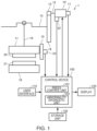
- FIG. 1 is a diagram illustrating an example of a configuration of a press machine (servo press machine) according to an embodiment of the invention.
- a press machine 1 converts the rotation of a servo motor 10 into a vertical reciprocating motion (reciprocating linear motion, ascending/descending motion) of a slide 17 by an eccentric mechanism for converting a rotational motion into a linear motion, and performs press working on a workpiece material by utilizing the vertical reciprocating motion of the slide 17.
- the press machine 1 includes the servo motor 10, an encoder 11, a drive shaft 12, a drive gear 13, a main gear 14, a crank shaft 15, a connecting rod 16, a slide 17, a bolster 18, a control device 100, a user interface 110, a display 120, and a storage unit 130.
- the press machine is not limited to a servo press machine, and may be, for example, a mechanical press using a flywheel or a linear motion press using a ball screw.
- the encoder may be provided at the shaft end of the crank shaft 15 or the shaft end of the ball screw.
- the drive shaft 12 is connected to the rotation axis of the servo motor 10, and the drive gear 13 is connected to the drive shaft 12.
- the main gear 14 is engaged with the drive gear 13, the crank shaft 15 is connected to the main gear 14, and the connecting rod 16 is connected to the crank shaft 15.
- the rotating shafts such as the drive shaft 12 and the crank shaft 15 are supported by appropriately provided bearings (not illustrated).
- the crank shaft 15 and the connecting rod 16 form the eccentric mechanism.
- This eccentric mechanism allows the slide 17 connected to the connecting rod 16 to ascend and descend with respect to the stationary bolster 18.
- the slide 17 is guided by the slide guide 19.
- the upper die 20 is attached to the slide 17, and the lower die 21 is attached to the bolster 18.
- a slide adjustment mechanism (not illustrated) is provided at a connecting portion between the connecting rod 16 and the slide 17.
- the connecting rod 16 and the slide 17 may be connected to each other through a plunger (not illustrated) without being directly connected. In this case, a plunger guide (not illustrated) for vertically guiding the plunger is provided.
- the servo motor 10 is provided with a sensor 22 for detecting vibration of the bearing of the servo motor 10, and the slide guide 19 is provided with a sensor 23 for detecting vibration of the slide guide 19.
- a sensor 22 for detecting vibration of the bearing of the servo motor 10 and the slide guide 19 is provided with a sensor 23 for detecting vibration of the slide guide 19.
- an acceleration sensor may be used.
- the data detected by the sensors 22 and 23 are output to the control device 100.
- the control device 100 includes a press control unit 101 and an abnormality diagnostic unit 102.
- the press control unit 101 controls the ascending/descending motion of the slide 17 based on the predetermined slide motion stored in the storage unit 130. More specifically, the press control unit 101 calculates a motor rotation position command value from a command for the position and speed of the slide 17 defined by the slide motion, and controls the rotation position, rotation speed, and current of the servo motor 10 based on the rotation position command.
- the rotation position of the servo motor 10 is detected by the encoder 11 attached to the servo motor 10.
- the press control unit 101 controls the operation of the conveying device (for example, a transfer feeder) for conveying a workpiece material.
- the press control unit 101 controls the operation of the automatic die changing device.
- the abnormality diagnostic unit 102 acquires data from sensors 22 and 23 while the slide 17 moves between the bottom dead point and the top dead point at a predetermined speed.
- the phrase "slide 17 moves between the bottom dead point and the top dead point” may mean that the slide 17 moves from the top dead point to the bottom dead point, that the slide 17 moves from the bottom dead point to the top dead point, that the slide 17 moves from near the top dead point (a predetermined position lower than the top dead point) to near the bottom dead point (a predetermined position higher than the bottom dead point), or that the slide 17 moves from near the bottom dead point to near the top dead point.
- the position of the slide 17 may be detected from the output of the encoder 11.
- the abnormality diagnostic unit 102 performs abnormality diagnosis of the press machine 1 based on the data acquired from the sensors 22 and 23, and outputs the diagnostic result to the press control unit 101.
- the press control unit 101 outputs the diagnostic result to the display 120.
- the storage unit 130 stores, in advance, data (normal-time data) acquired from the sensors 22 and 23 while the slide 17 moves normally between the bottom dead point and the top dead point at a predetermined speed.
- the "normal-time” refers to a state in which the press machine is in a new state, such as during a trial run at the time of manufacturing the machine, or when the user is operating the machine with a die attached for the first time after delivery of the machine.
- the abnormality diagnostic unit 102 performs abnormality diagnosis by comparing the data (measurement data) acquired from the sensors 22 and 23 at the time of diagnosis with the normal-time data.
- the user can capture a sign of abnormality (seizing, or the like) of the bearing of the servo motor 10 from the diagnostic result of the abnormality diagnosis based on the measurement data from the sensor 22, and can capture a sign of abnormality of the slide guide 19 from the diagnostic result of the abnormality diagnosis based on the measurement data from the sensor 23.
- abnormality diagnosis is executed when a die is changed change with no processing load. Specifically, abnormality diagnosis is performed by acquiring data from the sensors 22 and 23 in each of the following timings: when the slide 17 is descended from the top dead point to the bottom dead point to remove a die (current die); when the slide 17 is ascended from the bottom dead point to the top dead point to carry in a next die; when the slide 17 is descended from the top dead point to the bottom dead point to attach the next die; and when the slide 17 is ascended from the bottom dead point to the top dead point to start production.
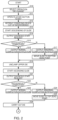
- FIGS. 2 to 4 are flowcharts illustrating the flow of die change processing and abnormality diagnosis processing when die change is automatically performed (when the press machine 1 is provided with the automatic die changing device).
- FIGS. 2 and 3 are flowcharts illustrating the processing flow of the press control unit 101.
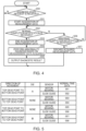
- FIG. 4 a flowchart illustrating the processing flow by the abnormality diagnostic unit 102. It is assumed that the slide 17 is stopped at the top dead point at the start of die change.
- step S10 in FIG. 2 When the operation of "die change” (step S10 in FIG. 2 ) is selected by the user in the user interface 110, and a start button “start” is operated (step S11), the press control unit 101 performs control for retreating the conveying device out of the interference (step S12). Next, the press control unit 101 starts descending the slide 17 (step S13) and outputs a diagnosis start request to the abnormality diagnostic unit 102 (step S14). Next, the press control unit 101 determines whether the descending of the slide 17 is normally completed (the slide 17 moves from the top dead point to the bottom dead point at a predetermined speed and stops at the bottom dead point) (step S15).
- step S15 when the descending is normally completed (Y in step S15), the press control unit 101 outputs a normal completion notification to the abnormality diagnostic unit 102 (step S16).
- step S16 when the descending is not normally completed (for example, when the slide 17 is stopped before the bottom dead point by the user's operation) (N in step S15), the press control unit 101 outputs an abnormal completion notification to the abnormality diagnostic unit 102 (step S17), and moves the slide 17 to the bottom dead point and stops it (step S18).
- the abnormality diagnostic unit 102 When receiving the diagnosis start request (Y of step S50 in FIG. 4 ), the abnormality diagnostic unit 102 starts acquiring data (measurement data) from the sensors 22 and 23 (step S51). Next, the abnormality diagnostic unit 102 determines whether the normal completion notification is received (step S52), and when the normal completion notification is received (Y of step S52), the acquisition of measurement data is completed (step S53), the acquired measurement data is compared with the normal-time data to perform abnormality diagnosis (step S54), and a result of the diagnosis is output to the press control unit 101 (step S55).
- the abnormality diagnostic unit 102 determines whether the abnormal completion notification is received (step S56), and when the abnormal completion notification is received (Y in step S56), the acquired measurement data is discarded (step S57), and a diagnostic result is not output.
- the storage unit 130 stores normal-time data for each moving direction (movement from the top dead point to the bottom dead point, movement from the bottom dead point to the top dead point), the presence/absence and type of dies, and the type of sensors (the sensor 22 for detecting vibration of the motor bearing, and the sensor 23).
- the sensor 22 for detecting vibration of the motor bearing and the sensor 23.
- the normal-time data "001” is data acquired from the sensor 22 normally while the slide 17 moves from the top dead point to the bottom dead point with a die "A” attached and the normal-time data "002" is data acquired from the sensor 23 under the similar condition
- the normal-time data "003” is data acquired from the sensor 22 normally while the slide 17 to which no die is attached moves from the bottom dead point to the top dead point and the normal-time data "004" is data acquired from the sensor 23 under the similar condition
- the normal-time data "005" is data acquired from the sensor 22 normally while the slide 17 to which no die is attached moves from the top dead point to the bottom dead point
- the normal-time data "006” is data acquired from the sensor 23 under the similar condition
- the normal-time data "007” is the data acquired from sensor 22 normally while the slide 17 to which a die "B” is attached moves from the bottom dead point to the top dead point and the normal-time data "008” is the data acquired from the sensor 23 under the similar condition.
- the abnormality diagnostic unit 102 compares measurement data (data acquired by the sensor 22 while the slide 17 to which the die “A” is attached moves from the top dead point to the bottom dead point) from the sensor 22 which has started data acquisition in diagnosis start request (step S14) and has ended the data acquisition with the normal completion notification (step S16), with the normal-time data "001" in FIG. 5 acquired under the same measurement conditions, to perform abnormality diagnosis.
- the abnormality diagnostic unit 102 also compares measurement data (data acquired by the sensor 23 while slide 17 to which the die "A" is attached moves from the top dead point to the bottom dead point) from the sensor 23, which has been acquired in the same manner, with the normal-time data "002" in FIG. 5 to perform abnormality diagnosis.
- the measurement data and the normal-time data are time-series data of sensor values.
- a plurality of intervals are set for each of the measurement data and the normal-time data, and the difference between them is obtained for each interval.
- the measurement data and the normal-time data are subjected to a Fast Fourier Transform (FFT) to determine the difference between them for each frequency band.
- FFT Fast Fourier Transform
- machine learning supervised learning
- abnormality diagnosis may be performed by inputting the measurement data into the learned model.
- the press control unit 101 controls the automatic die changing device to unclamp the upper die 20 (die “A") after outputting the normal completion notification in step S16 or stopping the slide 17 at the bottom dead point in step S18 (step S19).
- the press control unit 101 starts ascending the slide 17 (step S20) and outputs a diagnosis start request to the abnormality diagnostic unit 102 (step S21).
- the press control unit 101 determines whether ascending of the slide 17 is normally completed (the slide 17 moves from the bottom dead point to the top dead point at a predetermined speed and stops at the top dead point) (step S22).
- step S22 when the ascending is normally completed (Y in step S22), the press control unit 101 outputs a normal completion notification to the abnormality diagnostic unit 102 (step S23).
- the press control unit 101 when the ascending is not normally completed (for example, when the slide 17 is stopped before the top dead point by the user's operation) (N in step S22), the press control unit 101 outputs an abnormal completion notification to the abnormality diagnostic unit 102 (step S24) and moves the slide 17 to the top dead point and stops it (step S25).
- step S54 the abnormality diagnostic unit 102 compares the measurement data (data acquired by the sensor 22 while the slide 17 to which no die is attached moves from the bottom dead point to the top dead point) from the sensor 22 which has started data acquisition in the diagnosis start request (step S21) and has ended the data acquisition in the normal completion notification (step S23), with the normal-time data "003" in FIG. 5 , to perform the abnormality diagnosis.
- the abnormality diagnostic unit 102 also compares the measurement data (data acquired by the sensor 23 while slide 17 to which no die is attached moves from the bottom dead point to the top dead point), which has been acquired in the same manner, from the sensor 23, with the normal-time data "004" in FIG. 5 to perform the abnormality diagnosis.
- the press control unit 101 controls the automatic die changing device to carry out the die "A” (step S26), adjust the slide to the height of the next die (step S27 in FIG. 3 ), and carry in the next die (referred to as the die "B") (step S28).
- the press control unit 101 starts descending the slide 17 (step S29) and outputs a diagnosis start request to the abnormality diagnostic unit 102 (step S30).
- the press control unit 101 determines whether the descending of the slide 17 is normally completed (step S31).
- step S31 when the descending is normally completed (Y in step S31), the press control unit 101 outputs a normal completion notification to the abnormality diagnostic unit 102 (step S32).
- step S32 when the descending is not normally completed (N in step S31), the press control unit 101 outputs an abnormal completion notification to the abnormality diagnostic unit 102 (step S33) and moves the slide 17 to the bottom dead point and stops it (step S34).
- step S54 the abnormality diagnostic unit 102 compares the measurement data (data acquired by the sensor 22 while the slide 17 to which no die is attached normally moves from the top dead point to the bottom dead point) from the sensor 22, which has started data acquisition in the diagnosis start request (step S30) and has ended the data acquisition with the normal completion notification (step S32), with the normal-time data "005" in FIG. 5 , to perform the abnormality diagnosis.
- the abnormality diagnostic unit 102 also compares the measurement data (data acquired by the sensor 23 while slide 17 to which no die is attached normally moves from the top dead point to the bottom dead point), which has been acquired in the same manner, from the sensor 23, with the normal-time data "006" in FIG. 5 to perform abnormality diagnosis.
- the press control unit 101 controls the automatic die changing device to clamp the next upper die 20 (die “B") after outputting the normal completion notification in step S32 or stopping the slide 17 at the bottom dead point in step S34 (step S35).
- the press control unit 101 starts ascending the slide 17 (step S36) and outputs a diagnosis start request to the abnormality diagnostic unit 102 (step S37).
- the press control unit 101 determines whether the ascending of the slide 17 is normally completed (step S38). Then, when the ascending is normally completed (Y in step S38), the press control unit 101 outputs a normal completion notification to the abnormality diagnostic unit 102 (step S39). Alternatively, when the ascending is not normally completed (N of step S38), the press control unit 101 outputs an abnormal completion notification to the abnormality diagnostic unit 102 (step S40) and moves the slide 17 to the top dead point and stops it (step S41).
- step S54 the abnormality diagnostic unit 102 compares the measurement data (data acquired by the sensor 22 while the slide 17 to which the die "B" is attached moves from the bottom dead point to the top dead point) from the sensor 22 which has started data acquisition in a diagnosis start request (step S37) and has ended the data acquisition with the normal completion notification (step S39), with the normal-time data "007" in FIG. 5 , to perform the abnormality diagnosis.
- the abnormality diagnostic unit 102 also compares measurement data (data acquired by the sensor 23 while the slide 17 to which the die "B" is attached moves from the bottom dead point to the top dead point), which has been acquired in the same manner, from the sensor 23, with the normal-time data "008" in FIG. 5 to perform the abnormality diagnosis.
- step S42 the press control unit 101 starts production after outputting the normal completion notification in step S39 or stopping the slide 17 at the top dead point in step S41 (step S42).
- FIGS. 6 and 7 are flowcharts illustrating the processing flow of a press control unit 101 when die change is performed manually.
- the processing of the abnormality diagnostic unit 102 is the same as the processing in the case where die change is performed automatically ( FIG. 4 ), and thus a description thereof will be omitted.
- the same processing as those in the case of performing the die change automatically will be appropriately omitted.
- Step S68 when the user unclamps the upper die 20 (die “A") (step S68) and operates the operation button “ON” (step S69), the press control unit 101 starts ascending the slide 17 (step S70) and outputs a diagnosis start request to the abnormality diagnostic unit 102 (step S71).
- Steps S72 to S75 are the same as steps S22 to S25 in FIG. 2 , and thus description thereof is omitted.
- step S76 the user carries out the die "A” (step S76), performs slide adjustment according to the height of the next die (step S77 in FIG. 7 ), and carries in the next die (referred to as the die "B") (step S78).
- step S79 the press control unit 101 starts descending the slide 17 (step S80), and outputs a diagnosis start request to the abnormality diagnostic unit 102 (step S81).
- Steps S82 to S85 are the same as steps S31 to S34 in FIG. 3 , and thus description thereof is omitted.
- Step S86 when the user clamps the upper die 20 (die “B") (step S86) and operates the operation button “ON” (step S87), the press control unit 101 starts ascending the slide 17 (step S88) and outputs a diagnosis start request to the abnormality diagnostic unit 102 (step S89).
- Steps S90 to S94 are the same as steps S38 to S42 in FIG. 3 , and thus description thereof is omitted.
- the abnormality diagnosis is performed when a die is changed with no load is applied during processing, based on the measurement data acquired from the sensors 22 and 23 when the slide 17 moves (the slide 17 is descended to remove the die, the slide 17 is ascended to carry in the next die, the slide 17 is descended to mount the next die, the slide 17 is ascended to start production) in accordance with the die change.
- This enables to eliminate the influence of disturbance and improve the diagnostic accuracy of the abnormality diagnosis without imposing the workload for the abnormality diagnosis on the user.
- the abnormality diagnosis by performing the abnormality diagnosis in each of the four situations in which the combination of the moving direction of the slide 17 and the presence/absence of the die is different, it is possible to more easily capture the sign of abnormality.
- the abnormality diagnosis may be performed only in some of the four situations.
- the sensor used in the abnormality diagnosis is not limited to the bearing of the servo motor and the slide guide, and may be provided in other rotary sliding parts such as a bearing supporting a crank shaft of the press machine, or other reciprocating sliding parts such as a plunger guide.
- the sensor used in the abnormality diagnosis is not limited to a sensor for detecting vibration, and may be, for example, a sensor for measuring a current value of the servo motor 10 (current sensor for detecting the output current of a servo amplifier) or a sensor for measuring the sound generated in the sliding parts (motor bearing, slide guide, or the like) of the press machine 1.
- the senor may be mounted in the radial and thrust directions with respect to the shaft when the sliding part to be diagnosed is a rotating part such as a bearing.
- the sensors may be attached to the slide guide or the frame in contact with the slide guide in the X-axis, Y-axis, and Z-axis direction respectively.
- the main purpose is to make a diagnosis automatically at the time of die change.
- the same abnormality diagnosis may be made as long as the die is attached or detached, and there is no disturbance in operation.
Landscapes
- Engineering & Computer Science (AREA)
- Mechanical Engineering (AREA)
- Physics & Mathematics (AREA)
- General Physics & Mathematics (AREA)
- Automation & Control Theory (AREA)
- Control Of Presses (AREA)
- Presses And Accessory Devices Thereof (AREA)
Description
- The present invention relates to a press machine and a method for diagnosing abnormality of the press machine.
- When, in a press machine, sliding parts (for example, a bearing of a main motor, a slide guide, or the like) are seized or a frame is cracked, it takes a long time for restoration work (disassembly, repair, and re-assembly), and when the production line is stopped during that time, it will result in a big loss. Thus, both the press manufacturers and the product manufacturers are seeking ways to capture signs of abnormality. In
JP 2006-509631 T JP 2000-190096 A JP H11-320198 A - These devices measure vibration during production and are intended to monitor failure of a product or die. In the case of a press machine, there is a problem that the vibration generated in a frame due to processing load during production causes a large disturbance, and thus it is difficult to compare with the normal state. In order to bring the press machine into a no-load condition which is the standard for normal operation during production, for example, in the case of a transfer press, a transfer feeder is retracted to a position out of interference with a press, and the materials in all stages are retreated to the outside of a die. Further, a slide adjustment mechanism is driven to adjust the height position of a slide (slide adjustment) so that an upper die and a lower die do not interfere with each other while the slide descends from a top dead point to a bottom dead point, and finally the abnormality diagnosis can be operated. Under this condition, a no-load operation (idle running) is carried out, and the measured vibration is compared with the normal vibration to make an abnormality diagnosis. After the diagnosis is completed, the slide is adjusted to the height position for production, the materials are placed again in each stage, the transfer feeder is moved to the feed start position, and a selector switch is changed so that the operation of the press and the transfer feeder is interlocked. Thus, when the abnormality diagnosis of the press machine is performed under a no-load condition during production, the user's workload becomes excessive.
US 2008/178676 A1 relates a system according to the preamble of claim 1 and method for monitoring operation of a press assembly, in which, vibrations are measured at the first location and also at a second location during operation of the press. The vibrations measured at the first location are correlated with the vibrations measured at the second location, and a relationship between the vibrations at the first and second locations is established. Vibrations measured at the second location can then be adjusted and compared to the baseline vibration level to determine if adjustments to the press operation need to be made, or if certain press elements will need to be replaced prior to their expected life span.
WO 2020/174827 A1 relates a system collects training data in order to train a determination model of artificial intelligence that determines an abnormality of an industrial machine. The system includes a storage device and a processor. The processor determines an occurrence of a trigger related to an occurrence of the abnormality in the industrial machine, and extracts data corresponding to the trigger from the state data when the trigger occurs. The processor stores the data corresponding to the trigger as the training data. - The invention provides a press machine which can improve diagnostic accuracy of the abnormality diagnosis without imposing a workload on a user, and a method for diagnosing abnormality of the press machine.
- According to a first aspect of the invention, there is provided a press machine according to claim 1 that converts a rotation of a motor into a reciprocating linear motion of a slide and performs press working on a workpiece material, the press machine including:
- a press control unit that controls ascending/descending motion of the slide; and
- an abnormality diagnostic unit configured to perform abnormality diagnosis of the press machine based on data from a sensor provided in the press machine and to output a result of the abnormality diagnosis,
- the press control unit being configured to output a diagnosis start request to the abnormality diagnostic unit when starting ascending or descending the slide, and
- the abnormality diagnostic unit being configured to start acquiring the data from the sensor when receiving the diagnostic start request, and perform the abnormality diagnosis, based on the data acquired from the sensor while the slide moves at a predetermined speed between a bottom dead point and a top dead point in a press-no-load state.
- According to a second aspect of the invention, there is provided a method according to claim 7 for diagnosing abnormality of a press machine that converts a rotation of a motor into a reciprocating linear motion of a slide and performs press working on a workpiece material, the method including:
- a press control step of controlling ascending/descending motion of the slide; and
- an abnormality diagnosis step of performing abnormality diagnosis of the press machine based on data from a sensor provided in the press machine and outputting a result of the abnormality diagnosis,
- in the abnormality diagnosis step, the abnormality diagnosis being performed based on the data acquired from the sensor while the slide moves at a predetermined speed between a bottom dead point and a top dead point in a press-no-load state.
-
-
FIG. 1 is a diagram illustrating an example of a configuration of a press machine according to an embodiment of the invention. -
FIG. 2 is a flowchart illustrating a processing flow of a press control unit when a die is changed automatically. -
FIG. 3 is a flowchart illustrating a processing flow of the press control unit when a die is changed automatically. -
FIG. 4 is a flowchart illustrating a processing flow of an abnormality diagnostic unit when a die is changed automatically. -
FIG. 5 is a table illustrating an example of normal-time data. -
FIG. 6 is a flowchart illustrating a processing flow of a press control unit when a die is changed manually. -
FIG. 7 is a flowchart illustrating a processing flow of the press control unit when a die is changed manually. -
- (1) According to one embodiment of the invention, there is provided a press machine that converts a rotation of a motor into a reciprocating linear motion of a slide and performs press working on a workpiece material, the method including:
- a press control unit that controls ascending/descending motion of the slide; and
- an abnormality diagnostic unit configured to perform abnormality diagnosis of the press machine based on data from a sensor provided in the press machine and to output a result of the abnormality diagnosis,
- the abnormality diagnostic unit being configured to perform the abnormality diagnosis based on the data acquired from the sensor while the slide moves at a predetermined speed between a bottom dead point and a top dead point in a press-no-load state.
- Here, the press-no-load state means a state in which no processing load is applied to the press machine, that is, a state in which the die is not mounted, or a state in which the members of the upper die and the lower die do not contact each other while the slide moves between the bottom dead point and the top dead point even when the die is mounted.
- According to one embodiment of the invention, there is provided a method for diagnosing abnormality of a press machine that converts the rotation of a motor into a reciprocating linear motion of a slide and performs press working on a workpiece material, the method including:
- a press control step of controlling ascending/descending motion of the slide; and
- an abnormality diagnosis step of performing abnormality diagnosis of the press machine based on data from a sensor provided in the press machine and outputting a result of the abnormality diagnosis,
- in the abnormality diagnosis step, the abnormality diagnosis being performed based on the data acquired from the sensor while the slide moves at a predetermined speed between a bottom dead point and a top dead point in a press-no-load state.
- According to the above embodiment, by performing the abnormality diagnosis based on the data acquired while the slide moves between the bottom dead point and the top dead point at a predetermined speed in the press-no-load state, the influence of disturbance may be eliminated and the diagnosis accuracy may be improved without imposing a workload for unloading on a user.
- (2) In the press machine according to the above embodiment,
the abnormality diagnostic unit may be configured to perform the abnormality diagnosis at the time of die change, based on at least one of: - data acquired from the sensor while the slide, to which a die is attached, moves at a predetermined speed from the top dead point to the bottom dead point;
- data acquired from the sensor while the slide, to which no die is attached, moves at a predetermined speed from the bottom dead point to the top dead point;
- data acquired from the sensor while the slide, to which no die is attached, moves at a predetermined speed from the top dead point to the bottom dead point; and
- data acquired from the sensor while the slide, to which a die is attached, moves at a predetermined speed from the bottom dead point to the top dead point.
- When the slide moves between the bottom dead point and the top dead point with a die mounted, the members (for example, a gas cushion built into the die, stripper plate, bottom dead point stopper, or the like) of the upper die and the lower die come into contact with each other in the vicinity of the bottom dead point, which may apply a load to the press machine. In this case, the abnormality diagnosis may be performed by automatically adjusting the slide to ascend to the height position where the members of the upper die and the lower die do not come into contact with each other, or excluding data acquired while the members of the upper die and the lower die are in contact with each other.
- According to the above embodiment, by performing the abnormality diagnosis by acquiring data from the sensor when the slide moves (the slide is descended to remove the die, the slide is ascended to carry in the next die, the slide is descended to mount the next die, or the slide is ascended to start production) at the time of the die change, the abnormality diagnosis may be performed without imposing a workload on a user.
- (3) In the press machine according to the above embodiment,
- the press control unit may be configured to output an abnormal completion notification to the abnormality diagnostic unit when movement of the slide is not completed normally, and
- the abnormality diagnostic unit may be configured not to output a result of the abnormality diagnosis when the abnormal completion notification has been received.
- According to the above embodiment, the result of the abnormality diagnosis may be prevented from being output in a state where a normal diagnosis is not performed.
- (4) In the press machine according to the above embodiment,
the abnormality diagnostic unit may be configured to perform the abnormality diagnosis based on: - data previously acquired from the sensor while the slide moved normally between the bottom dead point and the top dead point at a predetermined speed; and
- data acquired from the sensor at the time of die change.
- (5) In the press machine according to the above embodiment,
the sensor may be a sensor configured to detect vibration of a bearing of the motor. - (6) In the press machine according to the above embodiment,
the sensor may be a sensor configured to detect vibration of a slide guide that guides the slide. - Hereinafter, embodiments of the invention will be described in detail with reference to the drawings.
-
FIG. 1 is a diagram illustrating an example of a configuration of a press machine (servo press machine) according to an embodiment of the invention. A press machine 1 converts the rotation of aservo motor 10 into a vertical reciprocating motion (reciprocating linear motion, ascending/descending motion) of aslide 17 by an eccentric mechanism for converting a rotational motion into a linear motion, and performs press working on a workpiece material by utilizing the vertical reciprocating motion of theslide 17. The press machine 1 includes theservo motor 10, anencoder 11, adrive shaft 12, adrive gear 13, amain gear 14, acrank shaft 15, a connectingrod 16, aslide 17, a bolster 18, acontrol device 100, auser interface 110, adisplay 120, and astorage unit 130. The press machine is not limited to a servo press machine, and may be, for example, a mechanical press using a flywheel or a linear motion press using a ball screw. In this case, the encoder may be provided at the shaft end of thecrank shaft 15 or the shaft end of the ball screw. - The
drive shaft 12 is connected to the rotation axis of theservo motor 10, and thedrive gear 13 is connected to thedrive shaft 12. Themain gear 14 is engaged with thedrive gear 13, thecrank shaft 15 is connected to themain gear 14, and the connectingrod 16 is connected to thecrank shaft 15. The rotating shafts such as thedrive shaft 12 and thecrank shaft 15 are supported by appropriately provided bearings (not illustrated). Thecrank shaft 15 and the connectingrod 16 form the eccentric mechanism. This eccentric mechanism allows theslide 17 connected to the connectingrod 16 to ascend and descend with respect to the stationary bolster 18. Theslide 17 is guided by theslide guide 19. Theupper die 20 is attached to theslide 17, and thelower die 21 is attached to the bolster 18. A slide adjustment mechanism (not illustrated) is provided at a connecting portion between the connectingrod 16 and theslide 17. The connectingrod 16 and theslide 17 may be connected to each other through a plunger (not illustrated) without being directly connected. In this case, a plunger guide (not illustrated) for vertically guiding the plunger is provided. - The
servo motor 10 is provided with asensor 22 for detecting vibration of the bearing of theservo motor 10, and theslide guide 19 is provided with asensor 23 for detecting vibration of theslide guide 19. As thesensors sensors control device 100. - The
control device 100 includes apress control unit 101 and an abnormalitydiagnostic unit 102. Thepress control unit 101 controls the ascending/descending motion of theslide 17 based on the predetermined slide motion stored in thestorage unit 130. More specifically, thepress control unit 101 calculates a motor rotation position command value from a command for the position and speed of theslide 17 defined by the slide motion, and controls the rotation position, rotation speed, and current of theservo motor 10 based on the rotation position command. The rotation position of theservo motor 10 is detected by theencoder 11 attached to theservo motor 10. - The
press control unit 101 controls the operation of the conveying device (for example, a transfer feeder) for conveying a workpiece material. When the press machine 1 is provided with an automatic die changing device including a means for conveying the dies (upper die 20, lower die 21) and a means for clamping and unclamping the dies, thepress control unit 101 controls the operation of the automatic die changing device. - The abnormality
diagnostic unit 102 acquires data fromsensors slide 17 moves between the bottom dead point and the top dead point at a predetermined speed. Note that the phrase "slide 17 moves between the bottom dead point and the top dead point" may mean that theslide 17 moves from the top dead point to the bottom dead point, that theslide 17 moves from the bottom dead point to the top dead point, that theslide 17 moves from near the top dead point (a predetermined position lower than the top dead point) to near the bottom dead point (a predetermined position higher than the bottom dead point), or that theslide 17 moves from near the bottom dead point to near the top dead point. The position of theslide 17 may be detected from the output of theencoder 11. The abnormalitydiagnostic unit 102 performs abnormality diagnosis of the press machine 1 based on the data acquired from thesensors press control unit 101. Thepress control unit 101 outputs the diagnostic result to thedisplay 120. Thestorage unit 130 stores, in advance, data (normal-time data) acquired from thesensors slide 17 moves normally between the bottom dead point and the top dead point at a predetermined speed. The "normal-time" refers to a state in which the press machine is in a new state, such as during a trial run at the time of manufacturing the machine, or when the user is operating the machine with a die attached for the first time after delivery of the machine. The abnormalitydiagnostic unit 102 performs abnormality diagnosis by comparing the data (measurement data) acquired from thesensors servo motor 10 from the diagnostic result of the abnormality diagnosis based on the measurement data from thesensor 22, and can capture a sign of abnormality of the slide guide 19 from the diagnostic result of the abnormality diagnosis based on the measurement data from thesensor 23. - In the press machine 1 of the present embodiment, abnormality diagnosis is executed when a die is changed change with no processing load. Specifically, abnormality diagnosis is performed by acquiring data from the
sensors slide 17 is descended from the top dead point to the bottom dead point to remove a die (current die); when theslide 17 is ascended from the bottom dead point to the top dead point to carry in a next die; when theslide 17 is descended from the top dead point to the bottom dead point to attach the next die; and when theslide 17 is ascended from the bottom dead point to the top dead point to start production. -
FIGS. 2 to 4 are flowcharts illustrating the flow of die change processing and abnormality diagnosis processing when die change is automatically performed (when the press machine 1 is provided with the automatic die changing device).FIGS. 2 and3 are flowcharts illustrating the processing flow of thepress control unit 101.FIG. 4 a flowchart illustrating the processing flow by the abnormalitydiagnostic unit 102. It is assumed that theslide 17 is stopped at the top dead point at the start of die change. - When the operation of "die change" (step S10 in
FIG. 2 ) is selected by the user in theuser interface 110, and a start button "start" is operated (step S11), thepress control unit 101 performs control for retreating the conveying device out of the interference (step S12). Next, thepress control unit 101 starts descending the slide 17 (step S13) and outputs a diagnosis start request to the abnormality diagnostic unit 102 (step S14). Next, thepress control unit 101 determines whether the descending of theslide 17 is normally completed (theslide 17 moves from the top dead point to the bottom dead point at a predetermined speed and stops at the bottom dead point) (step S15). Then, when the descending is normally completed (Y in step S15), thepress control unit 101 outputs a normal completion notification to the abnormality diagnostic unit 102 (step S16). Alternatively, when the descending is not normally completed (for example, when theslide 17 is stopped before the bottom dead point by the user's operation) (N in step S15), thepress control unit 101 outputs an abnormal completion notification to the abnormality diagnostic unit 102 (step S17), and moves theslide 17 to the bottom dead point and stops it (step S18). - When receiving the diagnosis start request (Y of step S50 in
FIG. 4 ), the abnormalitydiagnostic unit 102 starts acquiring data (measurement data) from thesensors 22 and 23 (step S51). Next, the abnormalitydiagnostic unit 102 determines whether the normal completion notification is received (step S52), and when the normal completion notification is received (Y of step S52), the acquisition of measurement data is completed (step S53), the acquired measurement data is compared with the normal-time data to perform abnormality diagnosis (step S54), and a result of the diagnosis is output to the press control unit 101 (step S55). When the normal completion notification is not received (N in step S52), the abnormalitydiagnostic unit 102 determines whether the abnormal completion notification is received (step S56), and when the abnormal completion notification is received (Y in step S56), the acquired measurement data is discarded (step S57), and a diagnostic result is not output. - Here, as listed in
FIG. 5 , thestorage unit 130 stores normal-time data for each moving direction (movement from the top dead point to the bottom dead point, movement from the bottom dead point to the top dead point), the presence/absence and type of dies, and the type of sensors (thesensor 22 for detecting vibration of the motor bearing, and the sensor 23). In the example illustrated inFIG. 5 , the normal-time data "001" is data acquired from thesensor 22 normally while theslide 17 moves from the top dead point to the bottom dead point with a die "A" attached and the normal-time data "002" is data acquired from thesensor 23 under the similar condition, the normal-time data "003" is data acquired from thesensor 22 normally while theslide 17 to which no die is attached moves from the bottom dead point to the top dead point and the normal-time data "004" is data acquired from thesensor 23 under the similar condition, the normal-time data "005" is data acquired from thesensor 22 normally while theslide 17 to which no die is attached moves from the top dead point to the bottom dead point and the normal-time data "006" is data acquired from thesensor 23 under the similar condition, and the normal-time data "007" is the data acquired fromsensor 22 normally while theslide 17 to which a die "B" is attached moves from the bottom dead point to the top dead point and the normal-time data "008" is the data acquired from thesensor 23 under the similar condition. - Assuming that an upper die "A" is attached to the
slide 17 that starts descending in step S13, in step S54, the abnormalitydiagnostic unit 102 compares measurement data (data acquired by thesensor 22 while theslide 17 to which the die "A" is attached moves from the top dead point to the bottom dead point) from thesensor 22 which has started data acquisition in diagnosis start request (step S14) and has ended the data acquisition with the normal completion notification (step S16), with the normal-time data "001" inFIG. 5 acquired under the same measurement conditions, to perform abnormality diagnosis. Then, the abnormalitydiagnostic unit 102 also compares measurement data (data acquired by thesensor 23 whileslide 17 to which the die "A" is attached moves from the top dead point to the bottom dead point) from thesensor 23, which has been acquired in the same manner, with the normal-time data "002" inFIG. 5 to perform abnormality diagnosis. The measurement data and the normal-time data are time-series data of sensor values. In the abnormality diagnosis, for example, a plurality of intervals are set for each of the measurement data and the normal-time data, and the difference between them is obtained for each interval. Then, when there are a predetermined number or more of intervals in which the difference between them is equal to or greater than a predetermined value, it is diagnosed that there is an abnormality, and in other cases, diagnosed that there is no abnormality. The measurement data and the normal-time data are subjected to a Fast Fourier Transform (FFT) to determine the difference between them for each frequency band. Then, when there are a predetermined number or more of frequency bands in which the difference between them is equal to or greater than a predetermined value, it is diagnosed that there is an abnormality, and in other cases, diagnosed that there is no abnormality. Further, machine learning (supervised learning) may be performed on the normal-time data and the FFT analysis results of the normal-time data to generate a learned model, and abnormality diagnosis may be performed by inputting the measurement data into the learned model. - Referring back to the description of
FIG. 2 , thepress control unit 101 controls the automatic die changing device to unclamp the upper die 20 (die "A") after outputting the normal completion notification in step S16 or stopping theslide 17 at the bottom dead point in step S18 (step S19). Next, thepress control unit 101 starts ascending the slide 17 (step S20) and outputs a diagnosis start request to the abnormality diagnostic unit 102 (step S21). Next, thepress control unit 101 determines whether ascending of theslide 17 is normally completed (theslide 17 moves from the bottom dead point to the top dead point at a predetermined speed and stops at the top dead point) (step S22). Then, when the ascending is normally completed (Y in step S22), thepress control unit 101 outputs a normal completion notification to the abnormality diagnostic unit 102 (step S23). Alternatively, when the ascending is not normally completed (for example, when theslide 17 is stopped before the top dead point by the user's operation) (N in step S22), thepress control unit 101 outputs an abnormal completion notification to the abnormality diagnostic unit 102 (step S24) and moves theslide 17 to the top dead point and stops it (step S25). - The processing by the abnormality
diagnostic unit 102 at this time is as illustrated inFIG. 4 . In step S54, the abnormalitydiagnostic unit 102 compares the measurement data (data acquired by thesensor 22 while theslide 17 to which no die is attached moves from the bottom dead point to the top dead point) from thesensor 22 which has started data acquisition in the diagnosis start request (step S21) and has ended the data acquisition in the normal completion notification (step S23), with the normal-time data "003" inFIG. 5 , to perform the abnormality diagnosis. Then, the abnormalitydiagnostic unit 102 also compares the measurement data (data acquired by thesensor 23 whileslide 17 to which no die is attached moves from the bottom dead point to the top dead point), which has been acquired in the same manner, from thesensor 23, with the normal-time data "004" inFIG. 5 to perform the abnormality diagnosis. - Referring back to the description of
FIG. 2 , after outputting the normal completion notification in step S23 or stopping theslide 17 at the top dead point in step S25, thepress control unit 101 controls the automatic die changing device to carry out the die "A" (step S26), adjust the slide to the height of the next die (step S27 inFIG. 3 ), and carry in the next die (referred to as the die "B") (step S28). Next, thepress control unit 101 starts descending the slide 17 (step S29) and outputs a diagnosis start request to the abnormality diagnostic unit 102 (step S30). Next, thepress control unit 101 determines whether the descending of theslide 17 is normally completed (step S31). Then, when the descending is normally completed (Y in step S31), thepress control unit 101 outputs a normal completion notification to the abnormality diagnostic unit 102 (step S32). Alternatively, when the descending is not normally completed (N in step S31), thepress control unit 101 outputs an abnormal completion notification to the abnormality diagnostic unit 102 (step S33) and moves theslide 17 to the bottom dead point and stops it (step S34). - The processing by the abnormality
diagnostic unit 102 at this time is as illustrated inFIG. 4 . In step S54, the abnormalitydiagnostic unit 102 compares the measurement data (data acquired by thesensor 22 while theslide 17 to which no die is attached normally moves from the top dead point to the bottom dead point) from thesensor 22, which has started data acquisition in the diagnosis start request (step S30) and has ended the data acquisition with the normal completion notification (step S32), with the normal-time data "005" inFIG. 5 , to perform the abnormality diagnosis. Then, the abnormalitydiagnostic unit 102 also compares the measurement data (data acquired by thesensor 23 whileslide 17 to which no die is attached normally moves from the top dead point to the bottom dead point), which has been acquired in the same manner, from thesensor 23, with the normal-time data "006" inFIG. 5 to perform abnormality diagnosis. - Referring back to the description of
FIG. 3 , thepress control unit 101 controls the automatic die changing device to clamp the next upper die 20 (die "B") after outputting the normal completion notification in step S32 or stopping theslide 17 at the bottom dead point in step S34 (step S35). Next, thepress control unit 101 starts ascending the slide 17 (step S36) and outputs a diagnosis start request to the abnormality diagnostic unit 102 (step S37). Next, thepress control unit 101 determines whether the ascending of theslide 17 is normally completed (step S38). Then, when the ascending is normally completed (Y in step S38), thepress control unit 101 outputs a normal completion notification to the abnormality diagnostic unit 102 (step S39). Alternatively, when the ascending is not normally completed (N of step S38), thepress control unit 101 outputs an abnormal completion notification to the abnormality diagnostic unit 102 (step S40) and moves theslide 17 to the top dead point and stops it (step S41). - The processing by the abnormality
diagnostic unit 102 at this time is as illustrated inFIG. 4 . In step S54, the abnormalitydiagnostic unit 102 compares the measurement data (data acquired by thesensor 22 while theslide 17 to which the die "B" is attached moves from the bottom dead point to the top dead point) from thesensor 22 which has started data acquisition in a diagnosis start request (step S37) and has ended the data acquisition with the normal completion notification (step S39), with the normal-time data "007" inFIG. 5 , to perform the abnormality diagnosis. Then, the abnormalitydiagnostic unit 102 also compares measurement data (data acquired by thesensor 23 while theslide 17 to which the die "B" is attached moves from the bottom dead point to the top dead point), which has been acquired in the same manner, from thesensor 23, with the normal-time data "008" inFIG. 5 to perform the abnormality diagnosis. - Referring back to the description of
FIG. 3 , thepress control unit 101 starts production after outputting the normal completion notification in step S39 or stopping theslide 17 at the top dead point in step S41 (step S42). -
FIGS. 6 and7 are flowcharts illustrating the processing flow of apress control unit 101 when die change is performed manually. The processing of the abnormalitydiagnostic unit 102 is the same as the processing in the case where die change is performed automatically (FIG. 4 ), and thus a description thereof will be omitted. In addition, with respect to the processing of thepress control unit 101, the same processing as those in the case of performing the die change automatically will be appropriately omitted. - When the user selects the operation of "inching" in the user interface 110 (step S60) and operates the operation button "ON" (step S61), the
press control unit 101 starts descending the slide 17 (step S62) and outputs a diagnosis start request to the abnormality diagnostic unit 102 (step S63). Steps S64 to S67 are the same as steps S15 to S18 inFIG. 2 , and thus description thereof is omitted. - Next, when the user unclamps the upper die 20 (die "A") (step S68) and operates the operation button "ON" (step S69), the
press control unit 101 starts ascending the slide 17 (step S70) and outputs a diagnosis start request to the abnormality diagnostic unit 102 (step S71). Steps S72 to S75 are the same as steps S22 to S25 inFIG. 2 , and thus description thereof is omitted. - Next, the user carries out the die "A" (step S76), performs slide adjustment according to the height of the next die (step S77 in
FIG. 7 ), and carries in the next die (referred to as the die "B") (step S78). Then, when the operation button "ON" is operated (step S79), thepress control unit 101 starts descending the slide 17 (step S80), and outputs a diagnosis start request to the abnormality diagnostic unit 102 (step S81). Steps S82 to S85 are the same as steps S31 to S34 inFIG. 3 , and thus description thereof is omitted. - Next, when the user clamps the upper die 20 (die "B") (step S86) and operates the operation button "ON" (step S87), the
press control unit 101 starts ascending the slide 17 (step S88) and outputs a diagnosis start request to the abnormality diagnostic unit 102 (step S89). Steps S90 to S94 are the same as steps S38 to S42 inFIG. 3 , and thus description thereof is omitted. - According to the present embodiment, the abnormality diagnosis is performed when a die is changed with no load is applied during processing, based on the measurement data acquired from the
sensors slide 17 moves (theslide 17 is descended to remove the die, theslide 17 is ascended to carry in the next die, theslide 17 is descended to mount the next die, theslide 17 is ascended to start production) in accordance with the die change. This enables to eliminate the influence of disturbance and improve the diagnostic accuracy of the abnormality diagnosis without imposing the workload for the abnormality diagnosis on the user. - In addition, according to the present embodiment, by performing the abnormality diagnosis in each of the four situations in which the combination of the moving direction of the
slide 17 and the presence/absence of the die is different, it is possible to more easily capture the sign of abnormality. The abnormality diagnosis may be performed only in some of the four situations. For example, by performing only the abnormality diagnosis based on the measurement data acquired while theslide 17 to which no die is attached moves at a predetermined speed from the top dead point to the bottom dead point (or from the bottom dead point to the top dead point) and not performing the abnormality diagnosis based on the measurement data acquired while theslide 17 to which the die is attached moves at a predetermined speed from the top dead point to the bottom dead point (or from the bottom dead point to the top dead point), it is not necessary to prepare normal-time data for each die type in advance. - The sensor used in the abnormality diagnosis is not limited to the bearing of the servo motor and the slide guide, and may be provided in other rotary sliding parts such as a bearing supporting a crank shaft of the press machine, or other reciprocating sliding parts such as a plunger guide. The sensor used in the abnormality diagnosis is not limited to a sensor for detecting vibration, and may be, for example, a sensor for measuring a current value of the servo motor 10 (current sensor for detecting the output current of a servo amplifier) or a sensor for measuring the sound generated in the sliding parts (motor bearing, slide guide, or the like) of the press machine 1.
- With respect to attaching of the sensor, the sensor may be mounted in the radial and thrust directions with respect to the shaft when the sliding part to be diagnosed is a rotating part such as a bearing. When the sliding part to be diagnosed is a reciprocating linear sliding part such as a slide guide, the sensors may be attached to the slide guide or the frame in contact with the slide guide in the X-axis, Y-axis, and Z-axis direction respectively.
- The main purpose is to make a diagnosis automatically at the time of die change. However, when a worker feels discomfort during production (when he/she finds that the sound and vibration, or the like differ from the normal state), the same abnormality diagnosis may be made as long as the die is attached or detached, and there is no disturbance in operation.
Claims (7)
- A press machine (1) that converts a rotation of a motor (10) into a reciprocating linear motion of a slide (17) and performs press working on a workpiece material, the press machine (1) comprising:a press control unit (101) that controls ascending/descending motion of the slide (17); andan abnormality diagnostic unit (102) configured to perform abnormality diagnosis of the press machine (1) based on data from a sensor (22, 23) provided in the press machine (1) and to output a result of the abnormality diagnosis,characterized in that the press control unit (101) is configured to output a diagnosis start request to the abnormality diagnostic unit (102) when starting ascending or descending the slide (17),the abnormality diagnostic unit (102) being configured to start acquiring the data from the sensor (22, 23) when receiving the diagnostic start request, and perform the abnormality diagnosis based on the data acquired from the sensor (22, 23) while the slide (17) moves at a predetermined speed between a bottom dead point and a top dead point in a press-no-load state.
- The press machine (1) according to claim 1, wherein
the abnormality diagnostic unit (102) is configured to perform the abnormality diagnosis at a time of die change, based on at least one of:data acquired from the sensor (22, 23) while the slide (17), to which a die (20, 21) is attached, moves at a predetermined speed from the top dead point to the bottom dead point;data acquired from the sensor (22, 23) while the slide (17), to which no die (20, 21) is attached, moves at a predetermined speed from the bottom dead point to the top dead point;data acquired from the sensor (22, 23) while the slide (17), to which no die (20, 21) is attached, moves at a predetermined speed from the top dead point to the bottom dead point; anddata acquired from the sensor (22, 23) while the slide (17), to which a die (20, 21) is attached, moves at a predetermined speed from the bottom dead point to the top dead point. - The press machine (1) according to claim 1 or 2, whereinthe press control unit (101) is configured to output an abnormal completion notification to the abnormality diagnostic unit (102) when movement of the slide (17) is not completed normally, andthe abnormality diagnostic unit (102) is configured not to output the result of the abnormality diagnosis when the abnormal completion notification has been received.
- The press machine (1) according to any one of claims 1 to 3, wherein
the abnormality diagnostic unit (102) is configured to perform the abnormality diagnosis, based on:data previously acquired from the sensor (22, 23) while the slide (17) moved normally between the bottom dead point and the top dead point at a predetermined speed; anddata acquired from the sensor (22, 23) at the time of die change. - The press machine (1) according to any one of claims 1 to 4, wherein
the sensor (22, 23) is a sensor (22, 23) configured to detect vibration of a bearing of the motor (10). - The press machine (1) according to any one of claim 1 to 4, wherein
the sensor (22, 23) is a sensor (23) configured to detect vibration of a slide guide (19) that guides the slide (17). - A method for diagnosing abnormality of a press machine (1) that converts a rotation of a motor (10) into a reciprocating linear motion of a slide (17) and performs press working on a workpiece material, the method comprising:a press control step of controlling ascending/descending motion of the slide (17); andan abnormality diagnosis step of performing abnormality diagnosis of the press machine (1) based on data from a sensor (22, 23) provided in the press machine (1) and outputting a result of the abnormality diagnosis,in the press control step, output a diagnosis start request to the abnormality diagnostic step when starting ascending or descending the slide (17), andin the abnormality diagnosis step, the abnormality diagnosis being started to acquire the data from the sensor (22, 23) when receiving the diagnostic start request, and being performed based on the data acquired from the sensor (22, 23) while the slide (17) moves at a predetermined speed between a bottom dead point and a top dead point in a press-no-load state.
Applications Claiming Priority (1)
| Application Number | Priority Date | Filing Date | Title |
|---|---|---|---|
| JP2021138858A JP7547295B2 (en) | 2021-08-27 | 2021-08-27 | Press machine and method for diagnosing abnormalities in press machine |
Publications (2)
| Publication Number | Publication Date |
|---|---|
| EP4140719A1 EP4140719A1 (en) | 2023-03-01 |
| EP4140719B1 true EP4140719B1 (en) | 2024-08-21 |
Family
ID=83050116
Family Applications (1)
| Application Number | Title | Priority Date | Filing Date |
|---|---|---|---|
| EP22191796.6A Active EP4140719B1 (en) | 2021-08-27 | 2022-08-23 | Press machine and method for diagnosing abnormality press machine |
Country Status (4)
| Country | Link |
|---|---|
| US (1) | US11772351B2 (en) |
| EP (1) | EP4140719B1 (en) |
| JP (1) | JP7547295B2 (en) |
| CN (1) | CN115891274A (en) |
Families Citing this family (1)
| Publication number | Priority date | Publication date | Assignee | Title |
|---|---|---|---|---|
| WO2024197372A1 (en) * | 2023-03-27 | 2024-10-03 | Fras-Le S.A. | System and process for monitoring misalignment between press columns |
Citations (7)
| Publication number | Priority date | Publication date | Assignee | Title |
|---|---|---|---|---|
| JPH02195498A (en) | 1989-01-25 | 1990-08-02 | Komatsu Ltd | Failure monitoring device |
| EP0612992A2 (en) | 1993-02-25 | 1994-08-31 | Toyota Jidosha Kabushiki Kaisha | Method of diagnosing pressing machine based on detected physical value as compared with reference |
| JPH1158093A (en) | 1997-08-19 | 1999-03-02 | Komatsu Ltd | Apparatus and method for setting upper limit position of servo press |
| US20080178676A1 (en) | 2007-01-29 | 2008-07-31 | Ford Motor Company | System and method for monitoring operation of a press assembly |
| JP2019123006A (en) | 2018-01-19 | 2019-07-25 | 住友重機械工業株式会社 | Press device and diagnostic method for press device |
| WO2021037514A1 (en) | 2019-08-23 | 2021-03-04 | Schuler Pressen Gmbh | Forming or separating device, and method for operating same |
| DE112019003513T5 (en) | 2018-07-10 | 2021-04-08 | Thk Co., Ltd. | THREADED SPINDLE DEVICE |
Family Cites Families (17)
| Publication number | Priority date | Publication date | Assignee | Title |
|---|---|---|---|---|
| JPS569099A (en) * | 1979-07-03 | 1981-01-29 | Toyo Tokushu Kiki Kk | Abnormality detecting method of automatic press |
| JPS59110500A (en) * | 1982-12-16 | 1984-06-26 | Yamada Dobby Co Ltd | Correcting device for bottom dead point position of press machine |
| JPH01320198A (en) | 1988-06-23 | 1989-12-26 | Yamato Shokai:Kk | Production of transparent synthetic resin molded object |
| JP3123456B2 (en) * | 1997-03-04 | 2001-01-09 | 村田機械株式会社 | Mold checking device for press machine |
| JP3818730B2 (en) | 1997-03-31 | 2006-09-06 | 株式会社小松製作所 | Servo press motion control device and control method thereof |
| US6114965A (en) | 1998-03-26 | 2000-09-05 | The Minster Machine Company | System for monitoring the dynamic tooling/shutheight deflection activity within a press machine |
| US6466840B1 (en) | 1998-11-03 | 2002-10-15 | The Minster Machine Company | Detailed die process severity analysis and optimization methodology |
| US6484106B1 (en) | 1999-07-30 | 2002-11-19 | The Minster Machine Company | Mechanical device productivity improvement with usage analysis, management, and implementation methodology for manufacturing facility |
| KR100509376B1 (en) * | 2001-12-21 | 2005-08-22 | 아이다엔지니어링가부시끼가이샤 | Press machine |
| DE10258660B4 (en) | 2002-12-13 | 2005-06-02 | Metso Lindemann Gmbh | Method and arrangement for operating state monitoring of presses, in particular baling presses |
| JP4818947B2 (en) * | 2007-02-16 | 2011-11-16 | 株式会社コスメック | Clamping device and overstroke detection system for the device |
| JP5160671B2 (en) * | 2011-07-29 | 2013-03-13 | コマツ産機株式会社 | Press machine and its top dead center detection method |
| JP5806875B2 (en) * | 2011-07-29 | 2015-11-10 | コマツ産機株式会社 | Press machine and slide position adjusting method thereof |
| US9586375B2 (en) * | 2013-07-03 | 2017-03-07 | Aida Engineering, Ltd. | Press machine controller |
| JP6945317B2 (en) * | 2017-03-27 | 2021-10-06 | コマツ産機株式会社 | Press system and control method of press system |
| JP7153546B2 (en) | 2018-11-29 | 2022-10-14 | 株式会社トヨタプロダクションエンジニアリング | Load detector |
| JP7357450B2 (en) | 2019-02-28 | 2023-10-06 | コマツ産機株式会社 | System and method for collecting learning data |
-
2021
- 2021-08-27 JP JP2021138858A patent/JP7547295B2/en active Active
-
2022
- 2022-08-09 CN CN202210950273.7A patent/CN115891274A/en active Pending
- 2022-08-15 US US17/887,780 patent/US11772351B2/en active Active
- 2022-08-23 EP EP22191796.6A patent/EP4140719B1/en active Active
Patent Citations (7)
| Publication number | Priority date | Publication date | Assignee | Title |
|---|---|---|---|---|
| JPH02195498A (en) | 1989-01-25 | 1990-08-02 | Komatsu Ltd | Failure monitoring device |
| EP0612992A2 (en) | 1993-02-25 | 1994-08-31 | Toyota Jidosha Kabushiki Kaisha | Method of diagnosing pressing machine based on detected physical value as compared with reference |
| JPH1158093A (en) | 1997-08-19 | 1999-03-02 | Komatsu Ltd | Apparatus and method for setting upper limit position of servo press |
| US20080178676A1 (en) | 2007-01-29 | 2008-07-31 | Ford Motor Company | System and method for monitoring operation of a press assembly |
| JP2019123006A (en) | 2018-01-19 | 2019-07-25 | 住友重機械工業株式会社 | Press device and diagnostic method for press device |
| DE112019003513T5 (en) | 2018-07-10 | 2021-04-08 | Thk Co., Ltd. | THREADED SPINDLE DEVICE |
| WO2021037514A1 (en) | 2019-08-23 | 2021-03-04 | Schuler Pressen Gmbh | Forming or separating device, and method for operating same |
Non-Patent Citations (3)
| Title |
|---|
| ANONYMOUS: " Betriebsanleitung Servopressenlinie (Version 4.1)", SCHULER, 1 January 2016 (2016-01-01), XP093279024 |
| D3A - EMPFANGSBESTÄTIGUNG BETRIEBSANLEITUNG |
| D4 - AUSZUG GESCHÄFTSBERICHT 2017 |
Also Published As
| Publication number | Publication date |
|---|---|
| US20230065386A1 (en) | 2023-03-02 |
| US11772351B2 (en) | 2023-10-03 |
| JP2023032616A (en) | 2023-03-09 |
| JP7547295B2 (en) | 2024-09-09 |
| EP4140719A1 (en) | 2023-03-01 |
| CN115891274A (en) | 2023-04-04 |
Similar Documents
| Publication | Publication Date | Title |
|---|---|---|
| KR101238112B1 (en) | Press apparatus | |
| CN108768110B (en) | Assembling method for motor rotating shaft and assembling machine for implementing method | |
| JPH0819900A (en) | Load detection/meeting device for press machine | |
| EP0585120A1 (en) | Mold clamping apparatus | |
| EP4140719A1 (en) | Press machine and method for diagnosing abnormality press machine | |
| EP2233282B1 (en) | Press machine | |
| JP3821549B2 (en) | Servo press mold protection apparatus and method | |
| JP4166119B2 (en) | Electric press machine | |
| JP2897658B2 (en) | Toggle punch press abnormality detection device | |
| JP4815077B2 (en) | Unloader abnormality diagnosis method | |
| JP4771630B2 (en) | Unloader abnormality diagnosis method | |
| KR102559051B1 (en) | Method and Apparatus for Measuring Press Die Parallelism and Press Apparatus Monitoring Method | |
| CN111906511B (en) | Flywheel machining device with automatic pin assembling and code printing functions | |
| JPS63180400A (en) | Automatic load control device for press machine | |
| JPH04367400A (en) | Press control method and device | |
| US12459029B2 (en) | Press system and control method of press system | |
| CN214522139U (en) | Multidirectional-adjustment automatic stamping device | |
| JP7001375B2 (en) | Die press device and die pressing method | |
| CN112345535A (en) | Cylindrical metal surface defect detection device based on machine vision | |
| JP6990051B2 (en) | Die press device and die pressing method | |
| JP2022152237A (en) | Forging-press machine and abnormality detection method for its workpiece attitude | |
| CN120715713B (en) | A stress detection device and method for drilling steel products | |
| JPH079200A (en) | Controlling method for servo motor press | |
| JP2018069244A (en) | Press body | |
| CN207991805U (en) | A kind of numerical control turret reliability constant speed and acceleration test apparatus |
Legal Events
| Date | Code | Title | Description |
|---|---|---|---|
| PUAI | Public reference made under article 153(3) epc to a published international application that has entered the european phase |
Free format text: ORIGINAL CODE: 0009012 |
|
| STAA | Information on the status of an ep patent application or granted ep patent |
Free format text: STATUS: THE APPLICATION HAS BEEN PUBLISHED |
|
| AK | Designated contracting states |
Kind code of ref document: A1 Designated state(s): AL AT BE BG CH CY CZ DE DK EE ES FI FR GB GR HR HU IE IS IT LI LT LU LV MC MK MT NL NO PL PT RO RS SE SI SK SM TR |
|
| STAA | Information on the status of an ep patent application or granted ep patent |
Free format text: STATUS: REQUEST FOR EXAMINATION WAS MADE |
|
| 17P | Request for examination filed |
Effective date: 20230901 |
|
| RBV | Designated contracting states (corrected) |
Designated state(s): AL AT BE BG CH CY CZ DE DK EE ES FI FR GB GR HR HU IE IS IT LI LT LU LV MC MK MT NL NO PL PT RO RS SE SI SK SM TR |
|
| REG | Reference to a national code |
Ref country code: DE Ref country code: DE Ref legal event code: R079 Ref document number: 602022005447 Country of ref document: DE Free format text: PREVIOUS MAIN CLASS: B30B0001000000 Ipc: G05B0023020000 |
|
| GRAP | Despatch of communication of intention to grant a patent |
Free format text: ORIGINAL CODE: EPIDOSNIGR1 |
|
| STAA | Information on the status of an ep patent application or granted ep patent |
Free format text: STATUS: GRANT OF PATENT IS INTENDED |
|
| RIC1 | Information provided on ipc code assigned before grant |
Ipc: B30B 1/26 20060101ALI20240322BHEP Ipc: B30B 1/18 20060101ALI20240322BHEP Ipc: B30B 15/00 20060101ALI20240322BHEP Ipc: B30B 15/02 20060101ALI20240322BHEP Ipc: B30B 15/26 20060101ALI20240322BHEP Ipc: G05B 23/00 20060101ALI20240322BHEP Ipc: B30B 15/28 20060101ALI20240322BHEP Ipc: B30B 15/14 20060101ALI20240322BHEP Ipc: B30B 1/00 20060101ALI20240322BHEP Ipc: G05B 23/02 20060101AFI20240322BHEP |
|
| INTG | Intention to grant announced |
Effective date: 20240418 |
|
| RAP3 | Party data changed (applicant data changed or rights of an application transferred) |
Owner name: AIDA ENGINEERING, LTD. |
|
| GRAS | Grant fee paid |
Free format text: ORIGINAL CODE: EPIDOSNIGR3 |
|
| GRAA | (expected) grant |
Free format text: ORIGINAL CODE: 0009210 |
|
| STAA | Information on the status of an ep patent application or granted ep patent |
Free format text: STATUS: THE PATENT HAS BEEN GRANTED |
|
| AK | Designated contracting states |
Kind code of ref document: B1 Designated state(s): AL AT BE BG CH CY CZ DE DK EE ES FI FR GB GR HR HU IE IS IT LI LT LU LV MC MK MT NL NO PL PT RO RS SE SI SK SM TR |
|
| REG | Reference to a national code |
Ref country code: GB Ref legal event code: FG4D |
|
| REG | Reference to a national code |
Ref country code: CH Ref legal event code: EP |
|
| REG | Reference to a national code |
Ref country code: IE Ref legal event code: FG4D |
|
| REG | Reference to a national code |
Ref country code: DE Ref legal event code: R096 Ref document number: 602022005447 Country of ref document: DE |
|
| REG | Reference to a national code |
Ref country code: LT Ref legal event code: MG9D |
|
| REG | Reference to a national code |
Ref country code: NL Ref legal event code: MP Effective date: 20240821 |
|
| PG25 | Lapsed in a contracting state [announced via postgrant information from national office to epo] |
Ref country code: NO Free format text: LAPSE BECAUSE OF FAILURE TO SUBMIT A TRANSLATION OF THE DESCRIPTION OR TO PAY THE FEE WITHIN THE PRESCRIBED TIME-LIMIT Effective date: 20241121 |
|
| REG | Reference to a national code |
Ref country code: AT Ref legal event code: MK05 Ref document number: 1716105 Country of ref document: AT Kind code of ref document: T Effective date: 20240821 |
|
| PG25 | Lapsed in a contracting state [announced via postgrant information from national office to epo] |
Ref country code: FI Free format text: LAPSE BECAUSE OF FAILURE TO SUBMIT A TRANSLATION OF THE DESCRIPTION OR TO PAY THE FEE WITHIN THE PRESCRIBED TIME-LIMIT Effective date: 20240821 Ref country code: NL Free format text: LAPSE BECAUSE OF FAILURE TO SUBMIT A TRANSLATION OF THE DESCRIPTION OR TO PAY THE FEE WITHIN THE PRESCRIBED TIME-LIMIT Effective date: 20240821 Ref country code: PL Free format text: LAPSE BECAUSE OF FAILURE TO SUBMIT A TRANSLATION OF THE DESCRIPTION OR TO PAY THE FEE WITHIN THE PRESCRIBED TIME-LIMIT Effective date: 20240821 Ref country code: GR Free format text: LAPSE BECAUSE OF FAILURE TO SUBMIT A TRANSLATION OF THE DESCRIPTION OR TO PAY THE FEE WITHIN THE PRESCRIBED TIME-LIMIT Effective date: 20241122 Ref country code: PT Free format text: LAPSE BECAUSE OF FAILURE TO SUBMIT A TRANSLATION OF THE DESCRIPTION OR TO PAY THE FEE WITHIN THE PRESCRIBED TIME-LIMIT Effective date: 20241223 |
|
| PG25 | Lapsed in a contracting state [announced via postgrant information from national office to epo] |
Ref country code: BG Free format text: LAPSE BECAUSE OF FAILURE TO SUBMIT A TRANSLATION OF THE DESCRIPTION OR TO PAY THE FEE WITHIN THE PRESCRIBED TIME-LIMIT Effective date: 20240821 |
|
| PG25 | Lapsed in a contracting state [announced via postgrant information from national office to epo] |
Ref country code: LV Free format text: LAPSE BECAUSE OF FAILURE TO SUBMIT A TRANSLATION OF THE DESCRIPTION OR TO PAY THE FEE WITHIN THE PRESCRIBED TIME-LIMIT Effective date: 20240821 |
|
| PG25 | Lapsed in a contracting state [announced via postgrant information from national office to epo] |
Ref country code: AT Free format text: LAPSE BECAUSE OF FAILURE TO SUBMIT A TRANSLATION OF THE DESCRIPTION OR TO PAY THE FEE WITHIN THE PRESCRIBED TIME-LIMIT Effective date: 20240821 Ref country code: IS Free format text: LAPSE BECAUSE OF FAILURE TO SUBMIT A TRANSLATION OF THE DESCRIPTION OR TO PAY THE FEE WITHIN THE PRESCRIBED TIME-LIMIT Effective date: 20241221 |
|
| PG25 | Lapsed in a contracting state [announced via postgrant information from national office to epo] |
Ref country code: HR Free format text: LAPSE BECAUSE OF FAILURE TO SUBMIT A TRANSLATION OF THE DESCRIPTION OR TO PAY THE FEE WITHIN THE PRESCRIBED TIME-LIMIT Effective date: 20240821 |
|
| PG25 | Lapsed in a contracting state [announced via postgrant information from national office to epo] |
Ref country code: RS Free format text: LAPSE BECAUSE OF FAILURE TO SUBMIT A TRANSLATION OF THE DESCRIPTION OR TO PAY THE FEE WITHIN THE PRESCRIBED TIME-LIMIT Effective date: 20241121 Ref country code: ES Free format text: LAPSE BECAUSE OF FAILURE TO SUBMIT A TRANSLATION OF THE DESCRIPTION OR TO PAY THE FEE WITHIN THE PRESCRIBED TIME-LIMIT Effective date: 20240821 |
|
| PG25 | Lapsed in a contracting state [announced via postgrant information from national office to epo] |
Ref country code: RS Free format text: LAPSE BECAUSE OF FAILURE TO SUBMIT A TRANSLATION OF THE DESCRIPTION OR TO PAY THE FEE WITHIN THE PRESCRIBED TIME-LIMIT Effective date: 20241121 Ref country code: PT Free format text: LAPSE BECAUSE OF FAILURE TO SUBMIT A TRANSLATION OF THE DESCRIPTION OR TO PAY THE FEE WITHIN THE PRESCRIBED TIME-LIMIT Effective date: 20241223 Ref country code: PL Free format text: LAPSE BECAUSE OF FAILURE TO SUBMIT A TRANSLATION OF THE DESCRIPTION OR TO PAY THE FEE WITHIN THE PRESCRIBED TIME-LIMIT Effective date: 20240821 Ref country code: NO Free format text: LAPSE BECAUSE OF FAILURE TO SUBMIT A TRANSLATION OF THE DESCRIPTION OR TO PAY THE FEE WITHIN THE PRESCRIBED TIME-LIMIT Effective date: 20241121 Ref country code: NL Free format text: LAPSE BECAUSE OF FAILURE TO SUBMIT A TRANSLATION OF THE DESCRIPTION OR TO PAY THE FEE WITHIN THE PRESCRIBED TIME-LIMIT Effective date: 20240821 Ref country code: LV Free format text: LAPSE BECAUSE OF FAILURE TO SUBMIT A TRANSLATION OF THE DESCRIPTION OR TO PAY THE FEE WITHIN THE PRESCRIBED TIME-LIMIT Effective date: 20240821 Ref country code: IS Free format text: LAPSE BECAUSE OF FAILURE TO SUBMIT A TRANSLATION OF THE DESCRIPTION OR TO PAY THE FEE WITHIN THE PRESCRIBED TIME-LIMIT Effective date: 20241221 Ref country code: HR Free format text: LAPSE BECAUSE OF FAILURE TO SUBMIT A TRANSLATION OF THE DESCRIPTION OR TO PAY THE FEE WITHIN THE PRESCRIBED TIME-LIMIT Effective date: 20240821 Ref country code: GR Free format text: LAPSE BECAUSE OF FAILURE TO SUBMIT A TRANSLATION OF THE DESCRIPTION OR TO PAY THE FEE WITHIN THE PRESCRIBED TIME-LIMIT Effective date: 20241122 Ref country code: FI Free format text: LAPSE BECAUSE OF FAILURE TO SUBMIT A TRANSLATION OF THE DESCRIPTION OR TO PAY THE FEE WITHIN THE PRESCRIBED TIME-LIMIT Effective date: 20240821 Ref country code: ES Free format text: LAPSE BECAUSE OF FAILURE TO SUBMIT A TRANSLATION OF THE DESCRIPTION OR TO PAY THE FEE WITHIN THE PRESCRIBED TIME-LIMIT Effective date: 20240821 Ref country code: BG Free format text: LAPSE BECAUSE OF FAILURE TO SUBMIT A TRANSLATION OF THE DESCRIPTION OR TO PAY THE FEE WITHIN THE PRESCRIBED TIME-LIMIT Effective date: 20240821 Ref country code: AT Free format text: LAPSE BECAUSE OF FAILURE TO SUBMIT A TRANSLATION OF THE DESCRIPTION OR TO PAY THE FEE WITHIN THE PRESCRIBED TIME-LIMIT Effective date: 20240821 |
|
| PG25 | Lapsed in a contracting state [announced via postgrant information from national office to epo] |
Ref country code: RO Free format text: LAPSE BECAUSE OF FAILURE TO SUBMIT A TRANSLATION OF THE DESCRIPTION OR TO PAY THE FEE WITHIN THE PRESCRIBED TIME-LIMIT Effective date: 20240821 Ref country code: SM Free format text: LAPSE BECAUSE OF FAILURE TO SUBMIT A TRANSLATION OF THE DESCRIPTION OR TO PAY THE FEE WITHIN THE PRESCRIBED TIME-LIMIT Effective date: 20240821 Ref country code: DK Free format text: LAPSE BECAUSE OF FAILURE TO SUBMIT A TRANSLATION OF THE DESCRIPTION OR TO PAY THE FEE WITHIN THE PRESCRIBED TIME-LIMIT Effective date: 20240821 |
|
| PG25 | Lapsed in a contracting state [announced via postgrant information from national office to epo] |
Ref country code: LU Free format text: LAPSE BECAUSE OF NON-PAYMENT OF DUE FEES Effective date: 20240823 |
|
| PG25 | Lapsed in a contracting state [announced via postgrant information from national office to epo] |
Ref country code: EE Free format text: LAPSE BECAUSE OF FAILURE TO SUBMIT A TRANSLATION OF THE DESCRIPTION OR TO PAY THE FEE WITHIN THE PRESCRIBED TIME-LIMIT Effective date: 20240821 |
|
| PG25 | Lapsed in a contracting state [announced via postgrant information from national office to epo] |
Ref country code: CZ Free format text: LAPSE BECAUSE OF FAILURE TO SUBMIT A TRANSLATION OF THE DESCRIPTION OR TO PAY THE FEE WITHIN THE PRESCRIBED TIME-LIMIT Effective date: 20240821 |
|
| PG25 | Lapsed in a contracting state [announced via postgrant information from national office to epo] |
Ref country code: SK Free format text: LAPSE BECAUSE OF FAILURE TO SUBMIT A TRANSLATION OF THE DESCRIPTION OR TO PAY THE FEE WITHIN THE PRESCRIBED TIME-LIMIT Effective date: 20240821 |
|
| REG | Reference to a national code |
Ref country code: DE Ref legal event code: R026 Ref document number: 602022005447 Country of ref document: DE |
|
| PLBI | Opposition filed |
Free format text: ORIGINAL CODE: 0009260 |
|
| PLAX | Notice of opposition and request to file observation + time limit sent |
Free format text: ORIGINAL CODE: EPIDOSNOBS2 |
|
| 26 | Opposition filed |
Opponent name: ANDRITZ SCHULER PRESSEN GMBH Effective date: 20250508 |
|
| REG | Reference to a national code |
Ref country code: BE Ref legal event code: MM Effective date: 20240831 |
|
| PG25 | Lapsed in a contracting state [announced via postgrant information from national office to epo] |
Ref country code: MC Free format text: LAPSE BECAUSE OF FAILURE TO SUBMIT A TRANSLATION OF THE DESCRIPTION OR TO PAY THE FEE WITHIN THE PRESCRIBED TIME-LIMIT Effective date: 20240821 |
|
| PG25 | Lapsed in a contracting state [announced via postgrant information from national office to epo] |
Ref country code: BE Free format text: LAPSE BECAUSE OF NON-PAYMENT OF DUE FEES Effective date: 20240831 |
|
| PG25 | Lapsed in a contracting state [announced via postgrant information from national office to epo] |
Ref country code: IE Free format text: LAPSE BECAUSE OF NON-PAYMENT OF DUE FEES Effective date: 20240823 |
|
| PG25 | Lapsed in a contracting state [announced via postgrant information from national office to epo] |
Ref country code: SE Free format text: LAPSE BECAUSE OF FAILURE TO SUBMIT A TRANSLATION OF THE DESCRIPTION OR TO PAY THE FEE WITHIN THE PRESCRIBED TIME-LIMIT Effective date: 20240821 |
|
| PLBB | Reply of patent proprietor to notice(s) of opposition received |
Free format text: ORIGINAL CODE: EPIDOSNOBS3 |
|
| PGFP | Annual fee paid to national office [announced via postgrant information from national office to epo] |
Ref country code: DE Payment date: 20250702 Year of fee payment: 4 |
|
| PGFP | Annual fee paid to national office [announced via postgrant information from national office to epo] |
Ref country code: IT Payment date: 20250901 Year of fee payment: 4 |
|
| PGFP | Annual fee paid to national office [announced via postgrant information from national office to epo] |
Ref country code: FR Payment date: 20250703 Year of fee payment: 4 |
|
| PG25 | Lapsed in a contracting state [announced via postgrant information from national office to epo] |
Ref country code: CY Free format text: LAPSE BECAUSE OF FAILURE TO SUBMIT A TRANSLATION OF THE DESCRIPTION OR TO PAY THE FEE WITHIN THE PRESCRIBED TIME-LIMIT; INVALID AB INITIO Effective date: 20220823 |
|
| PG25 | Lapsed in a contracting state [announced via postgrant information from national office to epo] |
Ref country code: HU Free format text: LAPSE BECAUSE OF FAILURE TO SUBMIT A TRANSLATION OF THE DESCRIPTION OR TO PAY THE FEE WITHIN THE PRESCRIBED TIME-LIMIT; INVALID AB INITIO Effective date: 20220823 |
|
| REG | Reference to a national code |
Ref country code: CH Ref legal event code: H13 Free format text: ST27 STATUS EVENT CODE: U-0-0-H10-H13 (AS PROVIDED BY THE NATIONAL OFFICE) Effective date: 20260324 |
|
| PG25 | Lapsed in a contracting state [announced via postgrant information from national office to epo] |
Ref country code: CH Free format text: LAPSE BECAUSE OF NON-PAYMENT OF DUE FEES Effective date: 20250831 |