EP4140637A1 - Workpiece support for thermal processing machine - Google Patents
Workpiece support for thermal processing machine Download PDFInfo
- Publication number
- EP4140637A1 EP4140637A1 EP21793209.4A EP21793209A EP4140637A1 EP 4140637 A1 EP4140637 A1 EP 4140637A1 EP 21793209 A EP21793209 A EP 21793209A EP 4140637 A1 EP4140637 A1 EP 4140637A1
- Authority
- EP
- European Patent Office
- Prior art keywords
- workpiece support
- workpiece
- supporting
- base member
- supporting member
- Prior art date
- Legal status (The legal status is an assumption and is not a legal conclusion. Google has not performed a legal analysis and makes no representation as to the accuracy of the status listed.)
- Granted
Links
Images




Classifications
-
- B—PERFORMING OPERATIONS; TRANSPORTING
- B23—MACHINE TOOLS; METAL-WORKING NOT OTHERWISE PROVIDED FOR
- B23K—SOLDERING OR UNSOLDERING; WELDING; CLADDING OR PLATING BY SOLDERING OR WELDING; CUTTING BY APPLYING HEAT LOCALLY, e.g. FLAME CUTTING; WORKING BY LASER BEAM
- B23K37/00—Auxiliary devices or processes, not specially adapted for a procedure covered by only one of the other main groups of this subclass
- B23K37/04—Auxiliary devices or processes, not specially adapted for a procedure covered by only one of the other main groups of this subclass for holding or positioning work
-
- B—PERFORMING OPERATIONS; TRANSPORTING
- B23—MACHINE TOOLS; METAL-WORKING NOT OTHERWISE PROVIDED FOR
- B23K—SOLDERING OR UNSOLDERING; WELDING; CLADDING OR PLATING BY SOLDERING OR WELDING; CUTTING BY APPLYING HEAT LOCALLY, e.g. FLAME CUTTING; WORKING BY LASER BEAM
- B23K26/00—Working by laser beam, e.g. welding, cutting or boring
- B23K26/08—Devices involving relative movement between laser beam and workpiece
- B23K26/10—Devices involving relative movement between laser beam and workpiece using a fixed support, i.e. involving moving the laser beam
-
- B—PERFORMING OPERATIONS; TRANSPORTING
- B23—MACHINE TOOLS; METAL-WORKING NOT OTHERWISE PROVIDED FOR
- B23K—SOLDERING OR UNSOLDERING; WELDING; CLADDING OR PLATING BY SOLDERING OR WELDING; CUTTING BY APPLYING HEAT LOCALLY, e.g. FLAME CUTTING; WORKING BY LASER BEAM
- B23K37/00—Auxiliary devices or processes, not specially adapted for a procedure covered by only one of the other main groups of this subclass
- B23K37/04—Auxiliary devices or processes, not specially adapted for a procedure covered by only one of the other main groups of this subclass for holding or positioning work
- B23K37/0408—Auxiliary devices or processes, not specially adapted for a procedure covered by only one of the other main groups of this subclass for holding or positioning work for planar work
-
- B—PERFORMING OPERATIONS; TRANSPORTING
- B23—MACHINE TOOLS; METAL-WORKING NOT OTHERWISE PROVIDED FOR
- B23Q—DETAILS, COMPONENTS, OR ACCESSORIES FOR MACHINE TOOLS, e.g. ARRANGEMENTS FOR COPYING OR CONTROLLING; MACHINE TOOLS IN GENERAL CHARACTERISED BY THE CONSTRUCTION OF PARTICULAR DETAILS OR COMPONENTS; COMBINATIONS OR ASSOCIATIONS OF METAL-WORKING MACHINES, NOT DIRECTED TO A PARTICULAR RESULT
- B23Q3/00—Devices holding, supporting, or positioning work or tools, of a kind normally removable from the machine
- B23Q3/02—Devices holding, supporting, or positioning work or tools, of a kind normally removable from the machine for mounting on a work-table, tool-slide, or analogous part
Definitions
- the present invention relates to a workpiece support member for a thermal processing machine.
- a plurality of plate-like workpiece support members are provided as supporting members for supporting a bottom surface of a sheet metal (workpiece) to be processed.
- the plurality of workpiece support members are arranged in a side-by-side manner at predetermined intervals on the workpiece support table with each plate surface thereof being perpendicular to a floor surface.
- each workpiece support member comes into contact with the bottom surface of the workpiece so that the workpiece is supported.
- Patent Literature 1 Japanese Patent Application Laid-Open Publication No. 2001-314998
- One aspect of the present invention provides a workpiece support member for a thermal processing machine in which a portion that supports a workpiece to be thermally processed can be replaced efficiently and easily.
- One aspect of the present invention is a workpiece support member for a thermal processing machine that is installed on a workpiece support table to support a workpiece to be thermally processed, and includes a base member formed of a plate-like member in a horizontally long shape and provided with a plurality of protruding supporting member attachment parts at predetermined distance intervals on an upper part thereof and a supporting member formed of a plate-like member of a carbon fiber in a horizontally long shape and installed in an attachable and removable state with a lower side thereof fitted alternately to a front surface and a rear surface of each of the adjacent supporting member attachment parts of the base member.
- a workpiece support member for a thermal processing machine in which a portion that supports a workpiece to be thermally processed can be replaced efficiently and easily.
- FIG 1 is an external perspective view showing a laser processing machine 1 that uses a workpiece support member 30 of a thermal processing machine according to one embodiment.
- the laser processing machine 1 according to the present embodiment performs cutting processing, and as shown in Figure 1 , a workpiece support table 3 for installing a workpiece W to be thermally processed is provided on a device base 2.
- a workpiece support table 3 for installing a workpiece W to be thermally processed is provided on a device base 2.
- a plurality of workpiece support members 30 that support the workpiece W to be processed are arranged in the X direction. The material and shape of the respective workpiece support members 30 will be described later.
- the laser processing machine 1 includes a gate-type frame 4 arranged in such a manner as to straddle the workpiece support table 3.
- the frame 4 includes side frames 41 and 42 and an upper frame 43.
- a carriage 5 that is movable in the Y direction is provided in the upper frame 43.
- a laser head 51 that emits a laser is attached to the carriage 5.
- the laser head 51 is configured to move arbitrarily in the X and Y directions above the workpiece W when the frame 4 is moved in the X direction by a dedicated drive system (not shown) and the carriage 5 is moved in the Y direction by a dedicated drive system (not shown).
- NC device 6 for controlling the laser processing machine 1 is attached to the frame 4.
- the NC device 6 controls the laser processing machine 1 according to processing data (NC data: numerical controlling data) for processing the workpiece W.
- NC device 6 is a control device that controls the laser processing machine 1.
- the workpiece W is cut when the laser head 51 irradiates the workpiece W with the laser while moving in the X direction or the Y direction by the frame 4 and the carriage 5, under the control of the NC device 6.
- the workpiece support member 30 that is installed on the workpiece support table 3 will be described. Since damage caused by thermal processing to the supported workpiece W is unavoidable, it is necessary to replace the workpiece support member 30 as appropriate. At this time, production cost can be suppressed by configuring the workpiece support member 30 such that only a member of the damaged portion can be partially replaced.
- Figure 2 shows the workpiece support member 30A that is the first configuration example of the workpiece support member 30 in one embodiment.
- Figure 2(a) is an external perspective view of the workpiece support member 30A
- Figure 2(b) is a side view of the workpiece support member 30A.
- the workpiece support member 30A is formed of a base member 31 composed of a plate-like member made of a metal in a horizontally long shape, and a plate-like member of a carbon fiber.
- the workpiece support member 30A includes a plurality of supporting members 33a, 33b, 33c, 33d, and 33e connected to the upper portion of the base member 31 by connecting members 32.
- the carbon fiber constituting the base member 31 will be described later.
- Figure 2(a) shows a case in which the number of supporting members connected to the base member 31 is five, but the number is not limited to this. The number of supporting members may be two or more, and may be one if partial replacement is not performed.
- Each of the supporting members 33a to 33e is composed of a long plate-like member including a long side shorter than that of the base member 31, and as shown in Figure 2(a) , is installed continuously along the upper side of the base member 31 in the lateral direction.
- Figure 2(a) shows a case in which each of the supporting members 33a to 33e is connected to the base member 31 by three connecting members 32, but the number of the connecting members 32 is not limited to this.
- the laser processing machine 1 executes the thermal processing to the supported workpiece W.
- any of the supporting members 33a to 33e of any of the workpiece support members 30A may be damaged.
- an operator detaches only a damaged supporting member of the corresponding workpiece support member 30A from the connecting member 32 and attaches a new supporting member for replacement.
- the workpiece support table 3 can be maintained in an appropriate state.
- Figure 3 shows the workpiece support member 30B that is the second configuration example of the workpiece support member 30 in one embodiment.
- Figure 3(a) is an external perspective view of the workpiece support member B
- Figure 3(b) is a side view of the workpiece support member B.
- the workpiece support member 30B includes a base member 34 composed of a plate-like member made of a metal in a horizontally long shape and a plurality of supporting members 35a, 35b, 35c, 35d, and 35e composed of a plate-like member of a carbon fiber and installed at the upper portion of the base member 34.
- Each of the supporting members 35a to 35e is composed of a long plate-like member including a long side shorter than that of the base member 34, and groove portions 351a to 351e into which the base member 34 can be fitted are respectively formed on the long side at the bottom part.
- These supporting members 35a to 35e are installed continuously in the lateral direction as shown in Figure 3(a) by fitting the upper side of the base member 34 into the respective groove portions 351a to 351e.
- the workpiece W to be processed When the workpiece W to be processed is placed on the workpiece support table 3 on which a plurality of the workpiece support members 30B described above are arranged, the upper ends of the supporting members 35a to 35e of each workpiece support member 30B come into contact with the bottom surface of the workpiece W so that the workpiece W is supported. Then, the laser processing machine executes the thermal processing to the workpiece W.
- the operator detaches only a damaged supporting member of the corresponding workpiece support member 30B from the base member 34 and attaches a new supporting member for replacement.
- the workpiece support table 3 can be maintained in an appropriate state.
- the connecting members 32 and the supporting members 33a to 33e may come into contact with each other and wear or deformation is caused in any of the members, resulting in rattling of a connecting mechanism thereof.
- rattling may be caused in a connecting mechanism between the groove portions 351a to 351e and the base member 34.
- the workpiece support member 30A uses the connecting members 32, the number of constituent members is large, which results in high production cost and high cost required for an attachment work.
- the workpiece support member 30B requires labor and production cost for processing the groove portions 351a to 351e when the supporting members 35a to 35e are produced.
- FIG. 4 is an external perspective view of the workpiece support member 300 that is the third configuration example of the workpiece support member in one embodiment.
- the workpiece support member 300 which is the third configuration example, is installed on the workpiece support table 3 to support the workpiece W to be thermally processed, and includes a base member 310 formed of a plate-like member in a horizontally long shape and provided with a plurality of protruding supporting member attachment parts 311 to 317 at predetermined distance intervals on an upper portion thereof, and supporting members 321 to 323 formed of a plate-like member in a horizontally long shape and installed in an attachable and removable state with a lower side thereof fitted alternately to a front surface and a rear surface of each of the adjacent supporting member attachment parts 311 to 317 of the base member 310.
- the supporting members 321 to 323 are formed of a carbon fiber.
- the supporting members 321 to 323 are each formed in a horizontally long shape including a long
- the workpiece support member 300 which is the third configuration example, will be described in detail.
- the workpiece support member 300 includes the base member 310 formed of a plate-like member made of a metal in a horizontally long shape, and the plurality of supporting members 321, 322, and 323 each formed of a plate-like member of a carbon fiber in a horizontally long shape including a long side shorter than that of the base member 310 and set up in a side-by-side manner on an upper part of the base member 310.
- the base member 310 is provided with the plurality of protruding supporting member attachment parts 311 to 317 at predetermined distance intervals narrower than those of the long sides of the supporting members 321 to 323.
- the supporting member attachment part 311 is provided at one end of the upper portion of the base member 310, and the supporting member attachment part 312 is provided at a position of the 1/6 length of the base member 310 from the end portion. Further, the supporting member attachment part 313 is provided at a position of the 1/3 length of the base member 310 from the end portion.
- the supporting member attachment part 314 is provided at a position of the 1/2 length of the base member 310 from the end portion.
- the supporting member attachment part 315 is provided at a position of the 2/3 length of the base member 310 from the end portion.
- the supporting member attachment part 316 is provided at a position of the 5/6 length of the base member 310 from the end portion. Further, the supporting member attachment part 317 is provided at the other end.
- the supporting members 321 to 323 are each formed by cutting out a thin plate, which is obtained by plain weave of a string-shaped carbon fiber, for example, a C/C composite (carbon fiber reinforced carbon composite) material, into a long shape.
- Plain weave is a method of weaving in which fibers are crossed vertically and horizontally one by one. Note that the method of weaving the carbon fiber may be satin weave, twill weave, crepe weave, or irregular weave, as long as the fiber is woven in any structure. Since the C/C composite material is reinforced by impregnating the woven carbon fiber with various substances, elasticity is generated when the C/C composite material is formed in a thin plate shape.
- the supporting members 321 to 323 are each formed in a horizontally long shape including a long side of about 1/3 of the long side of the base member 310. Then, by utilizing the elasticity of the carbon fiber, each lower side is fitted so as to be alternately caught in the front surface and the rear surface of the plurality of adjacent supporting member attachment parts of the base member 310.
- the left end of the lower side of the supporting member 321 is caught in the front surface of the supporting member attachment part 311 of the base member 310, the vicinity of the center thereof is caught in the rear surface of the supporting member attachment part 312 thereof, and the right end thereof is caught in the front surface of the supporting member attachment part 313 thereof, so that the supporting member 321 is fitted into the base member 310.
- the left end of the lower side of the supporting member 322 is caught in the front surface of the supporting member attachment part 313, the vicinity of the center thereof is caught in the rear surface of the supporting member attachment part 314 thereof, and the right end thereof is caught in the front surface of the supporting member attachment part 315 thereof, so that the supporting member 322 is fitted into the base member 310.
- the left end of the lower side of the supporting member 323 is caught in the front surface of the supporting member attachment part 315 thereof, the vicinity of the center thereof is caught in the rear surface of the supporting member attachment part 316 thereof, and the right end thereof is caught in the front surface of the supporting member attachment part 317 thereof, so that the supporting member 323 is fitted into the base member 310.
- the supporting members 321 to 323 When the supporting members 321 to 323 are fitted into the base member 310 in this manner, the supporting members 321 to 323 hold the supporting member attachment parts 311 to 317 of the base member 310 by the elastic force, thereby allowing the supporting member attachment parts 311 to 317 to be attached in a stable state without rattling.
- the supporting members 321 to 323 can be held as long as the supporting member attachment parts 311 to 317 are made of a material having an elastic property. Therefore, even if the supporting members 321 to 323 are formed of a conventional iron-based material or aluminum-based material, or copper-based material that is expensive, it is possible to attach the supporting member attachment parts 311 to 317 in a stable state.
- the string-shaped carbon fiber is used for the supporting members 321 to 323 because the string-shaped carbon fiber enables the supporting members 321 to 323 to be less likely weld to the workpiece W when the workpiece W is laser-cut and enables a dross generated when the workpiece W is cut to less likely adhere to the workpiece W, and the string-shaped carbon fiber is an elastic body.
- a plurality of the workpiece support members 300 described above are arranged on the workpiece support table 3, and while the workpiece W to be processed is placed on the workpiece support table 3, the thermal processing is performed to the workpiece W.
- the operator pulls the corresponding supporting member of the corresponding workpiece support member 300 upward and removes the supporting member from the base member 310. Then, a new supporting member is caught in the supporting member attachment part at the corresponding location to be attached. In this manner, each of the supporting members 321 to 323 is configured to be easily attached to and removed from the base member 310.
- the workpiece support member 300 described above for the workpiece support table 3, it is possible to replace only the damaged supporting member and efficiently regenerate the workpiece support member in a stable structure. Since the supporting member to be produced as a replacement member has a simple structure, the supporting member can be easily produced by blanking, which can suppress the production cost.
- the supporting members 321 to 323 by forming the supporting members 321 to 323 with the carbon fiber, it is possible to prevent metal, which is molten from the workpiece W during the thermal processing, from adhering.
- metal which is molten from the workpiece W during the thermal processing
- the amount of the metal melted from the workpiece W during the processing is large. Therefore, there is a possibility that the dross adheres to a bottom surface of the workpiece W and sandwiches the workpiece support member 300 from above, resulting in the molten metal adhering to the supporting members 321 to 323.
- the workpiece W and the supporting members 321 to 323 are in a state of being connected by the molten metal, and when the processed workpiece W is lifted by a forklift or the like, the corresponding supporting members 321 to 323 are also pulled upward.
- the supporting members 321 to 323 are pulled upward, the supporting members 321 to 323 come off from the base member 310, which causes inconvenience.
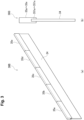
- FIG. 5 is an external perspective view of the workpiece support member 400 that is the fourth configuration example of the workpiece support member in one embodiment.
- the workpiece support member 400 includes a base member 410 formed of a plate-like member made of a metal in a horizontally long shape, and a plurality of supporting members 421 and 422 each formed of a plate-like member of a carbon fiber in a horizontally long shape including a long side shorter than that of the base member 410 and set up in a side-by-side manner at an upper portion of the base member 410.
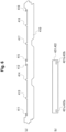
- Figure 6(a) and (b) show the workpiece support member 400 that is the fourth configuration example of the workpiece support member in one embodiment.
- Figure 6(a) is a front view of the base member 410
- Figure 6(b) is a front view of the supporting members 421 and 422.
- the supporting members 421 and 422 of the workpiece support member 400 which is the fourth configuration example, includes insertion holes 421a, 421b, 422a, and 422b at a lower part thereof, and the base member 410 includes hook portions 411, 412, 415, and 416 to be caught in the insertion holes 421a, 421b, 422a and 422b.
- the base member 410 includes, at the upper part thereof, the protruding hook portions 411 and 412 provided at corresponding positions of both ends of the supporting member 421 to be installed, and the hook portions 415 and 416 provided at corresponding positions of both ends of the supporting member 422. Further, the base member 410 includes supporting member attachment parts 413 and 414 provided between the hook portion 411 and the hook portion 412, and supporting member attachment parts 417 and 418 provided between the hook portion 415 and the hook portion 416.
- Figures 5 and 6(a) show a case in which there are two supporting member attachment parts provided between the hook portion 411 and the hook portion 412, and two supporting member attachment parts provided between the hook portion 415 and the hook portion 416.
- the number of the supporting member attachment parts is not limited to this, and may be one, or three or more.
- the supporting member 421 is formed in a horizontally long shape including a long side of about 1/2 of the long side of the base member 410, and includes the insertion holes 421a and 421b at both ends of the lower part thereof as shown in Figure 6(b) .
- the supporting member 422 also includes the insertion holes 422a and 422b at both ends of the lower part thereof. Then, by utilizing the elasticity of the carbon fiber, the hook portions are inserted into the insertion holes at the both ends in a state in which the respective lower sides are caught in the supporting member attachment parts of the base member 410.
- the hook portion 411 of the base member 410 is inserted into the insertion hole 421a at the left end of the lower side of the supporting member 421. Then, the central portion of the lower side is alternately caught in the front surface of the supporting member attachment part 413 and the rear surface of the supporting member attachment part 414. Further, the hook portion 412 is inserted into the insertion hole 421b at the right end of the lower side, so that the supporting member 421 is fitted into the base member 410.
- the hook portion 415 of the base member 410 is inserted into the insertion hole 422a at the left end of the lower side of the supporting member 422. Then, the central portion of the lower side is alternately caught in the rear surface of the supporting member attachment part 417 and the front surface of the supporting member attachment part 418. Further, the hook portion 416 is inserted into the insertion hole 422b at the right end of the lower side, so that the supporting member 422 is fitted into the base member 410.
- the supporting members 421 and 422 are fitted into the base member 410 in this manner, the hook portions 411, 412, 415, and 416 are caught in the insertion holes 421a, 421b, 422a, and 422b, respectively. Further, the supporting member attachment parts 413 and 414 are held by the lower side of the supporting member 421, and the supporting member attachment parts 417 and 418 are held by the lower side of the supporting member 422. As a result, the supporting members 421 and 422 are attached to the base member 410 in a stable state without being detached from the base member 410 even if the supporting members 421 and 422 are pulled upward.
- a plurality of the workpiece support members 400 described above are arranged on the workpiece support table 3, and while the workpiece W to be processed is placed on the workpiece support table 3, the thermal processing is performed to the workpiece W.
- the operator detaches the hook portion of the corresponding supporting member of the corresponding workpiece support member 400 from the insertion hole and pulls the supporting member upward, so that the supporting member is removed. Then, while the new supporting member is being caught in the supporting member attachment part, the hook portion is inserted into the insertion hole at the corresponding location so as to be attached.
- each of the supporting members 421 and 422 is configured to be easily attached to and removed from the base member 410.
Landscapes
- Physics & Mathematics (AREA)
- Optics & Photonics (AREA)
- Engineering & Computer Science (AREA)
- Mechanical Engineering (AREA)
- Plasma & Fusion (AREA)
- Laser Beam Processing (AREA)
- Jigs For Machine Tools (AREA)
Abstract
Description
- The present invention relates to a workpiece support member for a thermal processing machine.
- Conventionally, to a workpiece support table of a thermal processing machine such as a laser processing machine or a plasma processing machine, a plurality of plate-like workpiece support members are provided as supporting members for supporting a bottom surface of a sheet metal (workpiece) to be processed. The plurality of workpiece support members are arranged in a side-by-side manner at predetermined intervals on the workpiece support table with each plate surface thereof being perpendicular to a floor surface.
- When the workpiece to be processed is placed on the workpiece support table on which the plurality of such workpiece support members are arranged, the upper end portion of each workpiece support member comes into contact with the bottom surface of the workpiece so that the workpiece is supported.
- Patent Literature 1:
Japanese Patent Application Laid-Open Publication No. 2001-314998 - It is necessary to replace the above-described workpiece support members as appropriate because damage, which is caused by thermal processing to the supported workpiece, is unavoidable. At this time, if the workpiece support members are each composed of a single member, it is necessary to replace the entire member each time a workpiece support member is replaced, which causes problems that production cost is required and labor for replacement work is required.
- One aspect of the present invention provides a workpiece support member for a thermal processing machine in which a portion that supports a workpiece to be thermally processed can be replaced efficiently and easily.
- One aspect of the present invention is a workpiece support member for a thermal processing machine that is installed on a workpiece support table to support a workpiece to be thermally processed, and includes a base member formed of a plate-like member in a horizontally long shape and provided with a plurality of protruding supporting member attachment parts at predetermined distance intervals on an upper part thereof and a supporting member formed of a plate-like member of a carbon fiber in a horizontally long shape and installed in an attachable and removable state with a lower side thereof fitted alternately to a front surface and a rear surface of each of the adjacent supporting member attachment parts of the base member.
- According to one aspect of the present invention, it is possible to provide a workpiece support member for a thermal processing machine in which a portion that supports a workpiece to be thermally processed can be replaced efficiently and easily.
-
- [
Figure 1] Figure 1 is an external perspective view showing a laser processing machine that uses a workpiece support member for a thermal processing machine according to one embodiment. - [
Figure 2] Figure 2(a) is an external perspective view andFigure 2(b) is a side view of aworkpiece support member 30A, which is a first configuration example of the workpiece support member in one embodiment. - [
Figure 3] Figure 3(a) is an external perspective view andFigure 3(b) is a side view of aworkpiece support member 30B, which is a second configuration example of the workpiece support member in one embodiment. - [
Figure 4] Figure 4 is an external perspective view of aworkpiece support member 300 that is a third configuration example of the workpiece support member in one embodiment. - [
Figure 5] Figure 5 is an external perspective view of aworkpiece support member 400 that is a fourth configuration example of the workpiece support member in one embodiment. - [
Figure 6] Figure 6(a) is a front view of abase member 410 andFigure 6(b) is a front view of supportingmembers workpiece support member 400, which is the fourth configuration example of the workpiece support member in one embodiment. - Hereinafter, a laser processing machine, which is a thermal processing machine, that uses a workpiece support table on which a workpiece support member according to one embodiment is installed will be described with reference to the attached drawings.
-
Figure 1 is an external perspective view showing alaser processing machine 1 that uses aworkpiece support member 30 of a thermal processing machine according to one embodiment. Thelaser processing machine 1 according to the present embodiment performs cutting processing, and as shown inFigure 1 , a workpiece support table 3 for installing a workpiece W to be thermally processed is provided on adevice base 2. On the workpiece support table 3, a plurality ofworkpiece support members 30 that support the workpiece W to be processed are arranged in the X direction. The material and shape of the respectiveworkpiece support members 30 will be described later. - The
laser processing machine 1 includes a gate-type frame 4 arranged in such a manner as to straddle the workpiece support table 3. Theframe 4 includesside frames upper frame 43. - A
carriage 5 that is movable in the Y direction is provided in theupper frame 43. Alaser head 51 that emits a laser is attached to thecarriage 5. Thelaser head 51 is configured to move arbitrarily in the X and Y directions above the workpiece W when theframe 4 is moved in the X direction by a dedicated drive system (not shown) and thecarriage 5 is moved in the Y direction by a dedicated drive system (not shown). - An NC device (numerical control device) 6 for controlling the
laser processing machine 1 is attached to theframe 4. The NC device 6 controls thelaser processing machine 1 according to processing data (NC data: numerical controlling data) for processing the workpiece W. The NC device 6 is a control device that controls thelaser processing machine 1. - The workpiece W is cut when the
laser head 51 irradiates the workpiece W with the laser while moving in the X direction or the Y direction by theframe 4 and thecarriage 5, under the control of the NC device 6. - The
workpiece support member 30 that is installed on the workpiece support table 3 will be described. Since damage caused by thermal processing to the supported workpiece W is unavoidable, it is necessary to replace theworkpiece support member 30 as appropriate. At this time, production cost can be suppressed by configuring theworkpiece support member 30 such that only a member of the damaged portion can be partially replaced. - As first and second configuration examples of the
workpiece support member 30 in which a member can be partially replaced, aworkpiece support member 30A shown inFigure 2 and aworkpiece support member 30B shown inFigure 3 will be described. -
Figure 2 shows theworkpiece support member 30A that is the first configuration example of theworkpiece support member 30 in one embodiment.Figure 2(a) is an external perspective view of theworkpiece support member 30A, andFigure 2(b) is a side view of theworkpiece support member 30A. Theworkpiece support member 30A is formed of abase member 31 composed of a plate-like member made of a metal in a horizontally long shape, and a plate-like member of a carbon fiber. Theworkpiece support member 30A includes a plurality of supportingmembers base member 31 by connectingmembers 32. The carbon fiber constituting thebase member 31 will be described later.Figure 2(a) shows a case in which the number of supporting members connected to thebase member 31 is five, but the number is not limited to this. The number of supporting members may be two or more, and may be one if partial replacement is not performed. - Each of the supporting
members 33a to 33e is composed of a long plate-like member including a long side shorter than that of thebase member 31, and as shown inFigure 2(a) , is installed continuously along the upper side of thebase member 31 in the lateral direction.Figure 2(a) shows a case in which each of the supportingmembers 33a to 33e is connected to thebase member 31 by three connectingmembers 32, but the number of the connectingmembers 32 is not limited to this. - When the workpiece W to be processed is placed on the workpiece support table 3 on which a plurality of the
workpiece support members 30A described above are arranged, the upper ends of the supportingmembers 33a to 33e of eachworkpiece support member 30A come into contact with the bottom surface of the workpiece W so that the workpiece W is supported. Then, thelaser processing machine 1 executes the thermal processing to the supported workpiece W. - When the thermal processing is executed on the workpiece support table 3, any of the supporting
members 33a to 33e of any of theworkpiece support members 30A may be damaged. In this case, an operator detaches only a damaged supporting member of the correspondingworkpiece support member 30A from the connectingmember 32 and attaches a new supporting member for replacement. As a result, the workpiece support table 3 can be maintained in an appropriate state. - Next, a
workpiece support member 30B will be described.Figure 3 shows theworkpiece support member 30B that is the second configuration example of theworkpiece support member 30 in one embodiment.Figure 3(a) is an external perspective view of the workpiece support member B, andFigure 3(b) is a side view of the workpiece support member B. Theworkpiece support member 30B includes abase member 34 composed of a plate-like member made of a metal in a horizontally long shape and a plurality of supportingmembers base member 34. - Each of the supporting
members 35a to 35e is composed of a long plate-like member including a long side shorter than that of thebase member 34, andgroove portions 351a to 351e into which thebase member 34 can be fitted are respectively formed on the long side at the bottom part. These supportingmembers 35a to 35e are installed continuously in the lateral direction as shown inFigure 3(a) by fitting the upper side of thebase member 34 into therespective groove portions 351a to 351e. - When the workpiece W to be processed is placed on the workpiece support table 3 on which a plurality of the
workpiece support members 30B described above are arranged, the upper ends of the supportingmembers 35a to 35e of eachworkpiece support member 30B come into contact with the bottom surface of the workpiece W so that the workpiece W is supported. Then, the laser processing machine executes the thermal processing to the workpiece W. - When any of the supporting
members 35a to 35e of any of theworkpiece support member 30B is damaged, the operator detaches only a damaged supporting member of the correspondingworkpiece support member 30B from thebase member 34 and attaches a new supporting member for replacement. As a result, the workpiece support table 3 can be maintained in an appropriate state. - By using the
workpiece support member 30A or theworkpiece support member 30B as described above for the workpiece support table 3, it is possible to replace only the damaged supporting member and to regenerate the workpiece support member efficiently. - However, if the
workpiece support member 30A is repeatedly used, the connectingmembers 32 and the supportingmembers 33a to 33e may come into contact with each other and wear or deformation is caused in any of the members, resulting in rattling of a connecting mechanism thereof. In the similar manner, if theworkpiece support member 30B is repeatedly used, rattling may be caused in a connecting mechanism between thegroove portions 351a to 351e and thebase member 34. - Further, since the
workpiece support member 30A uses the connectingmembers 32, the number of constituent members is large, which results in high production cost and high cost required for an attachment work. In addition, theworkpiece support member 30B requires labor and production cost for processing thegroove portions 351a to 351e when the supportingmembers 35a to 35e are produced. - A
workpiece support member 300, which is a third configuration example configured to solve these problems, will be described.Figure 4 is an external perspective view of theworkpiece support member 300 that is the third configuration example of the workpiece support member in one embodiment. Theworkpiece support member 300, which is the third configuration example, is installed on the workpiece support table 3 to support the workpiece W to be thermally processed, and includes abase member 310 formed of a plate-like member in a horizontally long shape and provided with a plurality of protruding supportingmember attachment parts 311 to 317 at predetermined distance intervals on an upper portion thereof, and supportingmembers 321 to 323 formed of a plate-like member in a horizontally long shape and installed in an attachable and removable state with a lower side thereof fitted alternately to a front surface and a rear surface of each of the adjacent supportingmember attachment parts 311 to 317 of thebase member 310. The supportingmembers 321 to 323 are formed of a carbon fiber. The supportingmembers 321 to 323 are each formed in a horizontally long shape including a long side shorter than that of thebase member 310, and are installed in multiple numbers on thebase member 310. - Hereinafter, the
workpiece support member 300, which is the third configuration example, will be described in detail. As shown inFigure 4 , theworkpiece support member 300 includes thebase member 310 formed of a plate-like member made of a metal in a horizontally long shape, and the plurality of supportingmembers base member 310 and set up in a side-by-side manner on an upper part of thebase member 310. - The
base member 310 is provided with the plurality of protruding supportingmember attachment parts 311 to 317 at predetermined distance intervals narrower than those of the long sides of the supportingmembers 321 to 323. - Specifically, the supporting
member attachment part 311 is provided at one end of the upper portion of thebase member 310, and the supportingmember attachment part 312 is provided at a position of the 1/6 length of thebase member 310 from the end portion. Further, the supportingmember attachment part 313 is provided at a position of the 1/3 length of thebase member 310 from the end portion. The supportingmember attachment part 314 is provided at a position of the 1/2 length of thebase member 310 from the end portion. The supportingmember attachment part 315 is provided at a position of the 2/3 length of thebase member 310 from the end portion. The supportingmember attachment part 316 is provided at a position of the 5/6 length of thebase member 310 from the end portion. Further, the supportingmember attachment part 317 is provided at the other end. - The supporting
members 321 to 323 are each formed by cutting out a thin plate, which is obtained by plain weave of a string-shaped carbon fiber, for example, a C/C composite (carbon fiber reinforced carbon composite) material, into a long shape. Plain weave is a method of weaving in which fibers are crossed vertically and horizontally one by one. Note that the method of weaving the carbon fiber may be satin weave, twill weave, crepe weave, or irregular weave, as long as the fiber is woven in any structure. Since the C/C composite material is reinforced by impregnating the woven carbon fiber with various substances, elasticity is generated when the C/C composite material is formed in a thin plate shape. - The supporting
members 321 to 323 are each formed in a horizontally long shape including a long side of about 1/3 of the long side of thebase member 310. Then, by utilizing the elasticity of the carbon fiber, each lower side is fitted so as to be alternately caught in the front surface and the rear surface of the plurality of adjacent supporting member attachment parts of thebase member 310. - Specifically, by the operator for the attachment work, the left end of the lower side of the supporting
member 321 is caught in the front surface of the supportingmember attachment part 311 of thebase member 310, the vicinity of the center thereof is caught in the rear surface of the supportingmember attachment part 312 thereof, and the right end thereof is caught in the front surface of the supportingmember attachment part 313 thereof, so that the supportingmember 321 is fitted into thebase member 310. Further, the left end of the lower side of the supportingmember 322 is caught in the front surface of the supportingmember attachment part 313, the vicinity of the center thereof is caught in the rear surface of the supportingmember attachment part 314 thereof, and the right end thereof is caught in the front surface of the supportingmember attachment part 315 thereof, so that the supportingmember 322 is fitted into thebase member 310. Further, the left end of the lower side of the supportingmember 323 is caught in the front surface of the supportingmember attachment part 315 thereof, the vicinity of the center thereof is caught in the rear surface of the supportingmember attachment part 316 thereof, and the right end thereof is caught in the front surface of the supportingmember attachment part 317 thereof, so that the supportingmember 323 is fitted into thebase member 310. - When the supporting
members 321 to 323 are fitted into thebase member 310 in this manner, the supportingmembers 321 to 323 hold the supportingmember attachment parts 311 to 317 of thebase member 310 by the elastic force, thereby allowing the supportingmember attachment parts 311 to 317 to be attached in a stable state without rattling. Note that the supportingmembers 321 to 323 can be held as long as the supportingmember attachment parts 311 to 317 are made of a material having an elastic property. Therefore, even if the supportingmembers 321 to 323 are formed of a conventional iron-based material or aluminum-based material, or copper-based material that is expensive, it is possible to attach the supportingmember attachment parts 311 to 317 in a stable state. In the above-described embodiment, the string-shaped carbon fiber is used for the supportingmembers 321 to 323 because the string-shaped carbon fiber enables the supportingmembers 321 to 323 to be less likely weld to the workpiece W when the workpiece W is laser-cut and enables a dross generated when the workpiece W is cut to less likely adhere to the workpiece W, and the string-shaped carbon fiber is an elastic body. - A plurality of the
workpiece support members 300 described above are arranged on the workpiece support table 3, and while the workpiece W to be processed is placed on the workpiece support table 3, the thermal processing is performed to the workpiece W. When any of the supporting members is damaged by the thermal processing, the operator pulls the corresponding supporting member of the correspondingworkpiece support member 300 upward and removes the supporting member from thebase member 310. Then, a new supporting member is caught in the supporting member attachment part at the corresponding location to be attached. In this manner, each of the supportingmembers 321 to 323 is configured to be easily attached to and removed from thebase member 310. - By using the
workpiece support member 300 described above for the workpiece support table 3, it is possible to replace only the damaged supporting member and efficiently regenerate the workpiece support member in a stable structure. Since the supporting member to be produced as a replacement member has a simple structure, the supporting member can be easily produced by blanking, which can suppress the production cost. - In the
workpiece support member 300 according to the third configuration example described above, by forming the supportingmembers 321 to 323 with the carbon fiber, it is possible to prevent metal, which is molten from the workpiece W during the thermal processing, from adhering. However, when the workpiece W is thick, the amount of the metal melted from the workpiece W during the processing is large. Therefore, there is a possibility that the dross adheres to a bottom surface of the workpiece W and sandwiches theworkpiece support member 300 from above, resulting in the molten metal adhering to the supportingmembers 321 to 323. - If the molten metal is adhered in this manner, the workpiece W and the supporting
members 321 to 323 are in a state of being connected by the molten metal, and when the processed workpiece W is lifted by a forklift or the like, the corresponding supportingmembers 321 to 323 are also pulled upward. When the supportingmembers 321 to 323 are pulled upward, the supportingmembers 321 to 323 come off from thebase member 310, which causes inconvenience. - A
workpiece support member 400, which is a fourth configuration example configured to avoid this inconvenience, will be described.Figure 5 is an external perspective view of theworkpiece support member 400 that is the fourth configuration example of the workpiece support member in one embodiment. - The
workpiece support member 400 includes abase member 410 formed of a plate-like member made of a metal in a horizontally long shape, and a plurality of supportingmembers base member 410 and set up in a side-by-side manner at an upper portion of thebase member 410.Figure 6(a) and (b) show theworkpiece support member 400 that is the fourth configuration example of the workpiece support member in one embodiment.Figure 6(a) is a front view of thebase member 410, andFigure 6(b) is a front view of the supportingmembers members workpiece support member 400, which is the fourth configuration example, includesinsertion holes base member 410 includeshook portions insertion holes - Hereinafter, the
workpiece support member 400, which is the fourth configuration example, will be described in detail. As shown inFigures 5 and6 , thebase member 410 includes, at the upper part thereof, the protrudinghook portions member 421 to be installed, and thehook portions member 422. Further, thebase member 410 includes supportingmember attachment parts hook portion 411 and thehook portion 412, and supportingmember attachment parts hook portion 415 and thehook portion 416.Figures 5 and6(a) show a case in which there are two supporting member attachment parts provided between thehook portion 411 and thehook portion 412, and two supporting member attachment parts provided between thehook portion 415 and thehook portion 416. However, the number of the supporting member attachment parts is not limited to this, and may be one, or three or more. - The supporting
member 421 is formed in a horizontally long shape including a long side of about 1/2 of the long side of thebase member 410, and includes theinsertion holes Figure 6(b) . In the same manner, the supportingmember 422 also includes theinsertion holes base member 410. - Specifically, by the operator for the attachment work, the
hook portion 411 of thebase member 410 is inserted into theinsertion hole 421a at the left end of the lower side of the supportingmember 421. Then, the central portion of the lower side is alternately caught in the front surface of the supportingmember attachment part 413 and the rear surface of the supportingmember attachment part 414. Further, thehook portion 412 is inserted into theinsertion hole 421b at the right end of the lower side, so that the supportingmember 421 is fitted into thebase member 410. - Further, the
hook portion 415 of thebase member 410 is inserted into theinsertion hole 422a at the left end of the lower side of the supportingmember 422. Then, the central portion of the lower side is alternately caught in the rear surface of the supportingmember attachment part 417 and the front surface of the supportingmember attachment part 418. Further, thehook portion 416 is inserted into theinsertion hole 422b at the right end of the lower side, so that the supportingmember 422 is fitted into thebase member 410. - When the supporting
members base member 410 in this manner, thehook portions insertion holes member attachment parts member 421, and the supportingmember attachment parts member 422. As a result, the supportingmembers base member 410 in a stable state without being detached from thebase member 410 even if the supportingmembers - A plurality of the
workpiece support members 400 described above are arranged on the workpiece support table 3, and while the workpiece W to be processed is placed on the workpiece support table 3, the thermal processing is performed to the workpiece W. When any of the supporting members is damaged by the thermal processing, the operator detaches the hook portion of the corresponding supporting member of the correspondingworkpiece support member 400 from the insertion hole and pulls the supporting member upward, so that the supporting member is removed. Then, while the new supporting member is being caught in the supporting member attachment part, the hook portion is inserted into the insertion hole at the corresponding location so as to be attached. In this manner, each of the supportingmembers base member 410. - By using the
workpiece support member 400 as described above for the workpiece support table 3, it is possible to prevent the supportingmembers members workpiece support member 400 are sandwiched by the molten metal of the workpiece W during the thermal processing. - The present invention is not limited to the present embodiment described above, and various modifications can be made without departing from the summary of the present invention.
- The disclosure of the present application is related to the subject matter described in
Japanese Patent Application No. 2020-077114 filed on April 24, 2020
Claims (4)
- A workpiece support member for a thermal processing machine, the workpiece support member being installed on a workpiece support table to support a workpiece to be thermally processed, comprising:a base member formed of a plate-like member in a horizontally long shape, and provided with a plurality of protruding supporting member attachment parts at predetermined distance intervals on an upper part thereof; anda supporting member formed of a plate-like member in a horizontally long shape, and installed in an attachable and removable state with a lower side thereof fitted alternately to a front surface and a rear surface of each of the adjacent supporting member attachment parts of the base member.
- The workpiece support member for the thermal processing machine according to claim 1, wherein the supporting member is formed of a carbon fiber.
- The workpiece support member for the thermal processing machine according to claim 1 or 2, wherein the supporting member is formed in a horizontally long shape including a long side shorter than a long side of the base member, and installed in multiple numbers on the base member.
- The workpiece support member for the thermal processing machine according to any one of claims 1 to 3, whereinthe supporting member includes an insertion hole at a lower part thereof, andthe base member includes a hook portion to be caught in the insertion hole.
Applications Claiming Priority (2)
| Application Number | Priority Date | Filing Date | Title |
|---|---|---|---|
| JP2020077114A JP7312722B2 (en) | 2020-04-24 | 2020-04-24 | Work support for thermal processing machine |
| PCT/JP2021/015945 WO2021215416A1 (en) | 2020-04-24 | 2021-04-20 | Workpiece support for thermal processing machine |
Publications (3)
| Publication Number | Publication Date |
|---|---|
| EP4140637A1 true EP4140637A1 (en) | 2023-03-01 |
| EP4140637A4 EP4140637A4 (en) | 2023-09-20 |
| EP4140637B1 EP4140637B1 (en) | 2024-10-09 |
Family
ID=78269424
Family Applications (1)
| Application Number | Title | Priority Date | Filing Date |
|---|---|---|---|
| EP21793209.4A Active EP4140637B1 (en) | 2020-04-24 | 2021-04-20 | Workpiece support for thermal processing machine |
Country Status (5)
| Country | Link |
|---|---|
| US (1) | US12496663B2 (en) |
| EP (1) | EP4140637B1 (en) |
| JP (1) | JP7312722B2 (en) |
| CN (1) | CN115427189B (en) |
| WO (1) | WO2021215416A1 (en) |
Families Citing this family (1)
| Publication number | Priority date | Publication date | Assignee | Title |
|---|---|---|---|---|
| CN114641367B (en) * | 2019-10-31 | 2024-04-12 | 株式会社天田集团 | Workpiece support for workpiece support table and thermal processing machine |
Family Cites Families (25)
| Publication number | Priority date | Publication date | Assignee | Title |
|---|---|---|---|---|
| AU430717B2 (en) * | 1966-11-21 | 1972-11-30 | Hyne & Son Pty. Limited | Fencing panels |
| JPH0342177A (en) * | 1987-05-18 | 1991-02-22 | Totsuki Syst Kk | Work table for cutting device |
| JPS6453767A (en) * | 1987-05-18 | 1989-03-01 | Totsuki Syst Kk | Device for cutting duct material |
| JP2001105169A (en) * | 1999-09-30 | 2001-04-17 | Amada Co Ltd | Work-table in laser beam machine |
| JP2001170790A (en) * | 1999-12-10 | 2001-06-26 | Mitsubishi Electric Corp | Workpiece support |
| JP3069655U (en) * | 1999-12-15 | 2000-06-23 | ドリコシステム株式会社 | Carbon cutting surface plate |
| JP4305703B2 (en) * | 2000-03-01 | 2009-07-29 | 株式会社アマダ | Processing table skid |
| JP2001314998A (en) | 2000-05-02 | 2001-11-13 | Toyo Tanso Kk | Support member for heat processing device |
| KR100510958B1 (en) * | 2003-03-12 | 2005-08-30 | 정무수 | Ceramic support for cutter using heat |
| KR200388091Y1 (en) * | 2005-04-01 | 2005-06-29 | 캐스틸금속(주) | Cutting material supporting device |
| CN201103195Y (en) | 2007-08-24 | 2008-08-20 | 朱苏东 | Reinforcing mesh for concrete |
| KR100965050B1 (en) * | 2008-08-01 | 2010-06-21 | 에스티엑스조선해양 주식회사 | Non-ferrous material joining device of support for heating cutter and support for heating cutter using dissimilar materials |
| EP2255914B1 (en) * | 2009-05-28 | 2012-05-23 | BBM Buchmüller Metallwaren GmbH | Support Element for a Work or Cutting Bench for a Cutting Device |
| JP2011235340A (en) * | 2010-05-13 | 2011-11-24 | Ashfield:Kk | Surface plate for cutting |
| NL2008731C2 (en) * | 2012-04-27 | 2013-10-29 | Therp Holding B V | Work piece support with improved supporting elements. |
| JP2013244535A (en) * | 2012-05-30 | 2013-12-09 | Amada Co Ltd | Skid table for finishing machine |
| KR101269598B1 (en) * | 2013-01-29 | 2013-06-05 | (주)메가텍코리아 | Supporting apparatus for metal sheet cutting |
| KR101418538B1 (en) * | 2014-03-19 | 2014-07-11 | 최충호 | Workpiece support plates for laser cutting apparatus |
| US10124446B2 (en) * | 2015-02-11 | 2018-11-13 | M&R Printing Equipment, Inc. | Reversible workbed support members for laser cutting machine |
| KR101811683B1 (en) * | 2016-03-30 | 2017-12-22 | 강호경 | Worktable for laser cutting apparatus |
| CN206299132U (en) * | 2016-11-24 | 2017-07-04 | 中铁五局集团建筑工程有限责任公司 | A kind of reinforcing bar braiding structure |
| CN208329317U (en) * | 2018-05-23 | 2019-01-04 | 阳程(佛山)科技有限公司 | Cement plate reinforcement component, half prefabricated cement board and prefabricated cement board using it |
| JP2020077114A (en) | 2018-11-06 | 2020-05-21 | 大日本印刷株式会社 | Case and reading device |
| KR101987109B1 (en) * | 2018-11-09 | 2019-09-27 | 윤재훈 | Laser processing apparatus and processing method using the same |
| CN210046164U (en) * | 2019-03-01 | 2020-02-11 | 大族激光科技产业集团股份有限公司 | workbench |
-
2020
- 2020-04-24 JP JP2020077114A patent/JP7312722B2/en active Active
-
2021
- 2021-04-20 CN CN202180029259.7A patent/CN115427189B/en active Active
- 2021-04-20 US US17/919,893 patent/US12496663B2/en active Active
- 2021-04-20 WO PCT/JP2021/015945 patent/WO2021215416A1/en not_active Ceased
- 2021-04-20 EP EP21793209.4A patent/EP4140637B1/en active Active
Also Published As
| Publication number | Publication date |
|---|---|
| WO2021215416A1 (en) | 2021-10-28 |
| JP7312722B2 (en) | 2023-07-21 |
| CN115427189B (en) | 2025-12-12 |
| EP4140637A4 (en) | 2023-09-20 |
| US20230145893A1 (en) | 2023-05-11 |
| JP2021171792A (en) | 2021-11-01 |
| EP4140637B1 (en) | 2024-10-09 |
| CN115427189A (en) | 2022-12-02 |
| US12496663B2 (en) | 2025-12-16 |
Similar Documents
| Publication | Publication Date | Title |
|---|---|---|
| CN108367450B (en) | Workpiece conveying system and work piece conveying method | |
| EP2131997B1 (en) | Cutting machine, particularly for leather and similar materials | |
| EP4140637B1 (en) | Workpiece support for thermal processing machine | |
| TWI719011B (en) | Stencil printer and conveyor system therefor | |
| JP7351964B2 (en) | Component mounting system | |
| JP2019202868A (en) | Counterweight receiving tool for elevator and method of mounting counterweight receiving tool | |
| JP2021008031A (en) | Cutting system, adjustable sorting equipment and methods | |
| CN110582193B (en) | Optimization device and optimization method for component mounting line | |
| US12036599B2 (en) | Press brake | |
| JP7591440B2 (en) | Workpiece support for thermal cutting machine | |
| CN101992995A (en) | Elevator car | |
| CN214641095U (en) | Panel beating laser cutting machine's board | |
| US20240238916A1 (en) | Slat system and method for a laser cutter work surface | |
| EP4052838B1 (en) | Workpiece support member for use with workpiece support table, and thermal processing machine | |
| JP5216988B2 (en) | Frame | |
| JP2006312213A (en) | Press cutting apparatus and press cutting method | |
| JP2018024303A (en) | Vehicular seat | |
| JP7734081B2 (en) | laser processing machine | |
| EP4628229A1 (en) | Machining position layout method, and sheet metal machining method | |
| JP2021070046A (en) | Workpiece support body used for workpiece support table, and thermal processing machine | |
| JP2017109283A (en) | Suction device and work support device | |
| CN213764452U (en) | Machine tool for laser cutting | |
| JP2021171782A (en) | Workpiece support of thermal processing machine | |
| KR20120117082A (en) | Method for support member assembling and support member for ship | |
| CN216180579U (en) | Industrial robot |
Legal Events
| Date | Code | Title | Description |
|---|---|---|---|
| STAA | Information on the status of an ep patent application or granted ep patent |
Free format text: STATUS: THE INTERNATIONAL PUBLICATION HAS BEEN MADE |
|
| PUAI | Public reference made under article 153(3) epc to a published international application that has entered the european phase |
Free format text: ORIGINAL CODE: 0009012 |
|
| STAA | Information on the status of an ep patent application or granted ep patent |
Free format text: STATUS: REQUEST FOR EXAMINATION WAS MADE |
|
| 17P | Request for examination filed |
Effective date: 20221019 |
|
| AK | Designated contracting states |
Kind code of ref document: A1 Designated state(s): AL AT BE BG CH CY CZ DE DK EE ES FI FR GB GR HR HU IE IS IT LI LT LU LV MC MK MT NL NO PL PT RO RS SE SI SK SM TR |
|
| DAV | Request for validation of the european patent (deleted) | ||
| DAX | Request for extension of the european patent (deleted) | ||
| A4 | Supplementary search report drawn up and despatched |
Effective date: 20230821 |
|
| RIC1 | Information provided on ipc code assigned before grant |
Ipc: B23Q 3/02 20060101ALI20230814BHEP Ipc: B23K 26/10 20060101ALI20230814BHEP Ipc: B23K 37/04 20060101AFI20230814BHEP |
|
| GRAP | Despatch of communication of intention to grant a patent |
Free format text: ORIGINAL CODE: EPIDOSNIGR1 |
|
| STAA | Information on the status of an ep patent application or granted ep patent |
Free format text: STATUS: GRANT OF PATENT IS INTENDED |
|
| INTG | Intention to grant announced |
Effective date: 20240516 |
|
| GRAS | Grant fee paid |
Free format text: ORIGINAL CODE: EPIDOSNIGR3 |
|
| GRAA | (expected) grant |
Free format text: ORIGINAL CODE: 0009210 |
|
| STAA | Information on the status of an ep patent application or granted ep patent |
Free format text: STATUS: THE PATENT HAS BEEN GRANTED |
|
| AK | Designated contracting states |
Kind code of ref document: B1 Designated state(s): AL AT BE BG CH CY CZ DE DK EE ES FI FR GB GR HR HU IE IS IT LI LT LU LV MC MK MT NL NO PL PT RO RS SE SI SK SM TR |
|
| REG | Reference to a national code |
Ref country code: CH Ref legal event code: EP |
|
| REG | Reference to a national code |
Ref country code: DE Ref legal event code: R096 Ref document number: 602021020058 Country of ref document: DE |
|
| REG | Reference to a national code |
Ref country code: IE Ref legal event code: FG4D |
|
| P01 | Opt-out of the competence of the unified patent court (upc) registered |
Free format text: CASE NUMBER: APP_60707/2024 Effective date: 20241112 |
|
| REG | Reference to a national code |
Ref country code: LT Ref legal event code: MG9D |
|
| REG | Reference to a national code |
Ref country code: NL Ref legal event code: MP Effective date: 20241009 |
|
| REG | Reference to a national code |
Ref country code: AT Ref legal event code: MK05 Ref document number: 1730063 Country of ref document: AT Kind code of ref document: T Effective date: 20241009 |
|
| PG25 | Lapsed in a contracting state [announced via postgrant information from national office to epo] |
Ref country code: NL Free format text: LAPSE BECAUSE OF FAILURE TO SUBMIT A TRANSLATION OF THE DESCRIPTION OR TO PAY THE FEE WITHIN THE PRESCRIBED TIME-LIMIT Effective date: 20241009 |
|
| PG25 | Lapsed in a contracting state [announced via postgrant information from national office to epo] |
Ref country code: NL Free format text: LAPSE BECAUSE OF FAILURE TO SUBMIT A TRANSLATION OF THE DESCRIPTION OR TO PAY THE FEE WITHIN THE PRESCRIBED TIME-LIMIT Effective date: 20241009 |
|
| PG25 | Lapsed in a contracting state [announced via postgrant information from national office to epo] |
Ref country code: HR Free format text: LAPSE BECAUSE OF FAILURE TO SUBMIT A TRANSLATION OF THE DESCRIPTION OR TO PAY THE FEE WITHIN THE PRESCRIBED TIME-LIMIT Effective date: 20241009 Ref country code: PT Free format text: LAPSE BECAUSE OF FAILURE TO SUBMIT A TRANSLATION OF THE DESCRIPTION OR TO PAY THE FEE WITHIN THE PRESCRIBED TIME-LIMIT Effective date: 20250210 Ref country code: IS Free format text: LAPSE BECAUSE OF FAILURE TO SUBMIT A TRANSLATION OF THE DESCRIPTION OR TO PAY THE FEE WITHIN THE PRESCRIBED TIME-LIMIT Effective date: 20250209 |
|
| PG25 | Lapsed in a contracting state [announced via postgrant information from national office to epo] |
Ref country code: FI Free format text: LAPSE BECAUSE OF FAILURE TO SUBMIT A TRANSLATION OF THE DESCRIPTION OR TO PAY THE FEE WITHIN THE PRESCRIBED TIME-LIMIT Effective date: 20241009 |
|
| PG25 | Lapsed in a contracting state [announced via postgrant information from national office to epo] |
Ref country code: BG Free format text: LAPSE BECAUSE OF FAILURE TO SUBMIT A TRANSLATION OF THE DESCRIPTION OR TO PAY THE FEE WITHIN THE PRESCRIBED TIME-LIMIT Effective date: 20241009 |
|
| PG25 | Lapsed in a contracting state [announced via postgrant information from national office to epo] |
Ref country code: ES Free format text: LAPSE BECAUSE OF FAILURE TO SUBMIT A TRANSLATION OF THE DESCRIPTION OR TO PAY THE FEE WITHIN THE PRESCRIBED TIME-LIMIT Effective date: 20241009 |
|
| PG25 | Lapsed in a contracting state [announced via postgrant information from national office to epo] |
Ref country code: NO Free format text: LAPSE BECAUSE OF FAILURE TO SUBMIT A TRANSLATION OF THE DESCRIPTION OR TO PAY THE FEE WITHIN THE PRESCRIBED TIME-LIMIT Effective date: 20250109 |
|
| PG25 | Lapsed in a contracting state [announced via postgrant information from national office to epo] |
Ref country code: LV Free format text: LAPSE BECAUSE OF FAILURE TO SUBMIT A TRANSLATION OF THE DESCRIPTION OR TO PAY THE FEE WITHIN THE PRESCRIBED TIME-LIMIT Effective date: 20241009 Ref country code: GR Free format text: LAPSE BECAUSE OF FAILURE TO SUBMIT A TRANSLATION OF THE DESCRIPTION OR TO PAY THE FEE WITHIN THE PRESCRIBED TIME-LIMIT Effective date: 20250110 Ref country code: AT Free format text: LAPSE BECAUSE OF FAILURE TO SUBMIT A TRANSLATION OF THE DESCRIPTION OR TO PAY THE FEE WITHIN THE PRESCRIBED TIME-LIMIT Effective date: 20241009 |
|
| PG25 | Lapsed in a contracting state [announced via postgrant information from national office to epo] |
Ref country code: PL Free format text: LAPSE BECAUSE OF FAILURE TO SUBMIT A TRANSLATION OF THE DESCRIPTION OR TO PAY THE FEE WITHIN THE PRESCRIBED TIME-LIMIT Effective date: 20241009 |
|
| PG25 | Lapsed in a contracting state [announced via postgrant information from national office to epo] |
Ref country code: RS Free format text: LAPSE BECAUSE OF FAILURE TO SUBMIT A TRANSLATION OF THE DESCRIPTION OR TO PAY THE FEE WITHIN THE PRESCRIBED TIME-LIMIT Effective date: 20250109 |
|
| PG25 | Lapsed in a contracting state [announced via postgrant information from national office to epo] |
Ref country code: SM Free format text: LAPSE BECAUSE OF FAILURE TO SUBMIT A TRANSLATION OF THE DESCRIPTION OR TO PAY THE FEE WITHIN THE PRESCRIBED TIME-LIMIT Effective date: 20241009 |
|
| PGFP | Annual fee paid to national office [announced via postgrant information from national office to epo] |
Ref country code: DE Payment date: 20250422 Year of fee payment: 5 |
|
| PG25 | Lapsed in a contracting state [announced via postgrant information from national office to epo] |
Ref country code: DK Free format text: LAPSE BECAUSE OF FAILURE TO SUBMIT A TRANSLATION OF THE DESCRIPTION OR TO PAY THE FEE WITHIN THE PRESCRIBED TIME-LIMIT Effective date: 20241009 |
|
| REG | Reference to a national code |
Ref country code: DE Ref legal event code: R097 Ref document number: 602021020058 Country of ref document: DE |
|
| PG25 | Lapsed in a contracting state [announced via postgrant information from national office to epo] |
Ref country code: EE Free format text: LAPSE BECAUSE OF FAILURE TO SUBMIT A TRANSLATION OF THE DESCRIPTION OR TO PAY THE FEE WITHIN THE PRESCRIBED TIME-LIMIT Effective date: 20241009 |
|
| PG25 | Lapsed in a contracting state [announced via postgrant information from national office to epo] |
Ref country code: RO Free format text: LAPSE BECAUSE OF FAILURE TO SUBMIT A TRANSLATION OF THE DESCRIPTION OR TO PAY THE FEE WITHIN THE PRESCRIBED TIME-LIMIT Effective date: 20241009 |
|
| PG25 | Lapsed in a contracting state [announced via postgrant information from national office to epo] |
Ref country code: SK Free format text: LAPSE BECAUSE OF FAILURE TO SUBMIT A TRANSLATION OF THE DESCRIPTION OR TO PAY THE FEE WITHIN THE PRESCRIBED TIME-LIMIT Effective date: 20241009 |
|
| PG25 | Lapsed in a contracting state [announced via postgrant information from national office to epo] |
Ref country code: CZ Free format text: LAPSE BECAUSE OF FAILURE TO SUBMIT A TRANSLATION OF THE DESCRIPTION OR TO PAY THE FEE WITHIN THE PRESCRIBED TIME-LIMIT Effective date: 20241009 |
|
| PG25 | Lapsed in a contracting state [announced via postgrant information from national office to epo] |
Ref country code: IT Free format text: LAPSE BECAUSE OF FAILURE TO SUBMIT A TRANSLATION OF THE DESCRIPTION OR TO PAY THE FEE WITHIN THE PRESCRIBED TIME-LIMIT Effective date: 20241009 |
|
| PLBE | No opposition filed within time limit |
Free format text: ORIGINAL CODE: 0009261 |
|
| STAA | Information on the status of an ep patent application or granted ep patent |
Free format text: STATUS: NO OPPOSITION FILED WITHIN TIME LIMIT |
|
| PG25 | Lapsed in a contracting state [announced via postgrant information from national office to epo] |
Ref country code: SE Free format text: LAPSE BECAUSE OF FAILURE TO SUBMIT A TRANSLATION OF THE DESCRIPTION OR TO PAY THE FEE WITHIN THE PRESCRIBED TIME-LIMIT Effective date: 20241009 |
|
| 26N | No opposition filed |
Effective date: 20250710 |
|
| REG | Reference to a national code |
Ref country code: CH Ref legal event code: H13 Free format text: ST27 STATUS EVENT CODE: U-0-0-H10-H13 (AS PROVIDED BY THE NATIONAL OFFICE) Effective date: 20251125 |
|
| PG25 | Lapsed in a contracting state [announced via postgrant information from national office to epo] |
Ref country code: LU Free format text: LAPSE BECAUSE OF NON-PAYMENT OF DUE FEES Effective date: 20250420 |
|
| PG25 | Lapsed in a contracting state [announced via postgrant information from national office to epo] |
Ref country code: MC Free format text: LAPSE BECAUSE OF FAILURE TO SUBMIT A TRANSLATION OF THE DESCRIPTION OR TO PAY THE FEE WITHIN THE PRESCRIBED TIME-LIMIT Effective date: 20241009 |
|
| GBPC | Gb: european patent ceased through non-payment of renewal fee |
Effective date: 20250420 |
|
| REG | Reference to a national code |
Ref country code: BE Ref legal event code: MM Effective date: 20250430 |
|
| PG25 | Lapsed in a contracting state [announced via postgrant information from national office to epo] |
Ref country code: GB Free format text: LAPSE BECAUSE OF NON-PAYMENT OF DUE FEES Effective date: 20250420 |
|
| PG25 | Lapsed in a contracting state [announced via postgrant information from national office to epo] |
Ref country code: FR Free format text: LAPSE BECAUSE OF NON-PAYMENT OF DUE FEES Effective date: 20250430 |
|
| PG25 | Lapsed in a contracting state [announced via postgrant information from national office to epo] |
Ref country code: BE Free format text: LAPSE BECAUSE OF NON-PAYMENT OF DUE FEES Effective date: 20250430 |
|
| PG25 | Lapsed in a contracting state [announced via postgrant information from national office to epo] |
Ref country code: CH Free format text: LAPSE BECAUSE OF NON-PAYMENT OF DUE FEES Effective date: 20250430 |
|
| PG25 | Lapsed in a contracting state [announced via postgrant information from national office to epo] |
Ref country code: IE Free format text: LAPSE BECAUSE OF NON-PAYMENT OF DUE FEES Effective date: 20250420 |