EP4140288B1 - Mobiles autonomes landwirtschaftliches system und verfahren - Google Patents
Mobiles autonomes landwirtschaftliches system und verfahren Download PDFInfo
- Publication number
- EP4140288B1 EP4140288B1 EP22191424.5A EP22191424A EP4140288B1 EP 4140288 B1 EP4140288 B1 EP 4140288B1 EP 22191424 A EP22191424 A EP 22191424A EP 4140288 B1 EP4140288 B1 EP 4140288B1
- Authority
- EP
- European Patent Office
- Prior art keywords
- laser curtain
- mobile unit
- mode
- row
- laser
- Prior art date
- Legal status (The legal status is an assumption and is not a legal conclusion. Google has not performed a legal analysis and makes no representation as to the accuracy of the status listed.)
- Active
Links
Images


Classifications
-
- G—PHYSICS
- G05—CONTROLLING; REGULATING
- G05D—SYSTEMS FOR CONTROLLING OR REGULATING NON-ELECTRIC VARIABLES
- G05D1/00—Control of position, course, altitude or attitude of land, water, air or space vehicles, e.g. using automatic pilots
- G05D1/60—Intended control result
- G05D1/617—Safety or protection, e.g. defining protection zones around obstacles or avoiding hazards
- G05D1/622—Obstacle avoidance
- G05D1/637—Obstacle avoidance using safety zones of adjustable size or shape
-
- A—HUMAN NECESSITIES
- A01—AGRICULTURE; FORESTRY; ANIMAL HUSBANDRY; HUNTING; TRAPPING; FISHING
- A01D—HARVESTING; MOWING
- A01D75/00—Accessories for harvesters or mowers
- A01D75/18—Safety devices for parts of the machines
- A01D75/185—Avoiding collisions with obstacles
-
- A—HUMAN NECESSITIES
- A01—AGRICULTURE; FORESTRY; ANIMAL HUSBANDRY; HUNTING; TRAPPING; FISHING
- A01D—HARVESTING; MOWING
- A01D46/00—Picking of fruits, vegetables, hops, or the like; Devices for shaking trees or shrubs
- A01D46/30—Robotic devices for individually picking crops
-
- A—HUMAN NECESSITIES
- A01—AGRICULTURE; FORESTRY; ANIMAL HUSBANDRY; HUNTING; TRAPPING; FISHING
- A01D—HARVESTING; MOWING
- A01D75/00—Accessories for harvesters or mowers
- A01D75/20—Devices for protecting men or animals
-
- G—PHYSICS
- G01—MEASURING; TESTING
- G01S—RADIO DIRECTION-FINDING; RADIO NAVIGATION; DETERMINING DISTANCE OR VELOCITY BY USE OF RADIO WAVES; LOCATING OR PRESENCE-DETECTING BY USE OF THE REFLECTION OR RERADIATION OF RADIO WAVES; ANALOGOUS ARRANGEMENTS USING OTHER WAVES
- G01S17/00—Systems using the reflection or reradiation of electromagnetic waves other than radio waves, e.g. lidar systems
- G01S17/88—Lidar systems specially adapted for specific applications
-
- G—PHYSICS
- G05—CONTROLLING; REGULATING
- G05D—SYSTEMS FOR CONTROLLING OR REGULATING NON-ELECTRIC VARIABLES
- G05D1/00—Control of position, course, altitude or attitude of land, water, air or space vehicles, e.g. using automatic pilots
- G05D1/20—Control system inputs
- G05D1/24—Arrangements for determining position or orientation
- G05D1/246—Arrangements for determining position or orientation using environment maps, e.g. simultaneous localisation and mapping [SLAM]
-
- G—PHYSICS
- G05—CONTROLLING; REGULATING
- G05D—SYSTEMS FOR CONTROLLING OR REGULATING NON-ELECTRIC VARIABLES
- G05D1/00—Control of position, course, altitude or attitude of land, water, air or space vehicles, e.g. using automatic pilots
- G05D1/20—Control system inputs
- G05D1/24—Arrangements for determining position or orientation
- G05D1/247—Arrangements for determining position or orientation using signals provided by artificial sources external to the vehicle, e.g. navigation beacons
- G05D1/249—Arrangements for determining position or orientation using signals provided by artificial sources external to the vehicle, e.g. navigation beacons from positioning sensors located off-board the vehicle, e.g. from cameras
-
- G—PHYSICS
- G05—CONTROLLING; REGULATING
- G05D—SYSTEMS FOR CONTROLLING OR REGULATING NON-ELECTRIC VARIABLES
- G05D1/00—Control of position, course, altitude or attitude of land, water, air or space vehicles, e.g. using automatic pilots
- G05D1/60—Intended control result
- G05D1/617—Safety or protection, e.g. defining protection zones around obstacles or avoiding hazards
- G05D1/622—Obstacle avoidance
-
- A—HUMAN NECESSITIES
- A01—AGRICULTURE; FORESTRY; ANIMAL HUSBANDRY; HUNTING; TRAPPING; FISHING
- A01B—SOIL WORKING IN AGRICULTURE OR FORESTRY; PARTS, DETAILS, OR ACCESSORIES OF AGRICULTURAL MACHINES OR IMPLEMENTS, IN GENERAL
- A01B79/00—Methods for working soil
- A01B79/005—Precision agriculture
-
- A—HUMAN NECESSITIES
- A01—AGRICULTURE; FORESTRY; ANIMAL HUSBANDRY; HUNTING; TRAPPING; FISHING
- A01D—HARVESTING; MOWING
- A01D34/00—Mowers; Mowing apparatus of harvesters
- A01D34/006—Control or measuring arrangements
- A01D34/008—Control or measuring arrangements for automated or remotely controlled operation
-
- A—HUMAN NECESSITIES
- A01—AGRICULTURE; FORESTRY; ANIMAL HUSBANDRY; HUNTING; TRAPPING; FISHING
- A01D—HARVESTING; MOWING
- A01D41/00—Combines, i.e. harvesters or mowers combined with threshing devices
- A01D41/12—Details of combines
- A01D41/127—Control or measuring arrangements specially adapted for combines
- A01D41/1278—Control or measuring arrangements specially adapted for combines for automatic steering
-
- G—PHYSICS
- G01—MEASURING; TESTING
- G01S—RADIO DIRECTION-FINDING; RADIO NAVIGATION; DETERMINING DISTANCE OR VELOCITY BY USE OF RADIO WAVES; LOCATING OR PRESENCE-DETECTING BY USE OF THE REFLECTION OR RERADIATION OF RADIO WAVES; ANALOGOUS ARRANGEMENTS USING OTHER WAVES
- G01S17/00—Systems using the reflection or reradiation of electromagnetic waves other than radio waves, e.g. lidar systems
- G01S17/88—Lidar systems specially adapted for specific applications
- G01S17/93—Lidar systems specially adapted for specific applications for anti-collision purposes
- G01S17/931—Lidar systems specially adapted for specific applications for anti-collision purposes of land vehicles
Definitions
- the present invention relates to a mobile autonomous agricultural system and a method of controlling a powered mobile unit.
- EP 3 572 897 discloses a work vehicle including an electronic control system for automated driving that automatically drives the vehicle body.
- the electronic control system includes an obstacle detection module configured to detect presence or absence of an obstacle, and a contact avoidance control unit configured to perform, upon the obstacle detection module detecting an obstacle, contact avoidance control to keep the vehicle body from coming into contact with the obstacle.
- the obstacle detection module includes a plurality of obstacle searchers that are distributed on the front end portion and the right and left end portions of the vehicle body such that the front side and the right and left lateral sides of the vehicle body are search-target areas.
- a mobile autonomous agricultural system comprising: a powered mobile unit for carrying agricultural equipment, and configured to move along rows of crops; at least one laser curtain sensor configured to project a laser curtain away from the mobile unit; a location module configured to monitor a location of the mobile unit relative to a row; a controller configured to control the travel of the mobile unit; a safety module configured to: receive a location signal from the location module related to the location of the mobile unit relative to a row, select a mode of operation to process the laser curtain in a predefined laser curtain pattern, based on the received location signal, each mode of operation corresponding to a different predefined laser curtain pattern, and to generate a safety output in response to determining that the laser curtain is interrupted within the laser curtain pattern.
- the safety output may be a signal to control the mobile unit to slow or to stop.
- the mobile unit may comprise an arch profile extending along an axial direction.
- the mobile autonomous agricultural system may comprise a plurality of laser curtain sensors distributed around the mobile unit configured together to form the laser curtain.
- Each laser curtain sensor may be configured to project a respective laser plane which overlaps with at least one other laser plane to form the laser curtain.
- the safety module may be configured to select a default mode of operation unless any deviating criteria are met.
- the default mode may comprise processing the laser curtain in a laser curtain pattern which extends from the mobile unit in an axial direction up to a maximum axial distance from the mobile unit, and in a width direction, perpendicular to the axial direction, up to a maximum width distance from the mobile unit.
- the deviating criteria may comprise a first deviating criterion comprising the mobile unit being controlled to move from one row to another row, wherein when the first deviating criterion is met, the safety mode is configured to select a crabbing mode.
- the crabbing mode may comprise processing the laser curtain in a laser curtain pattern which extends from the mobile unit along the axial direction up to a minimum axial distance, and in a width direction, perpendicular to the axial direction, up to a maximum width distance.
- the deviating criteria may comprise a second deviating criterion comprising the mobile unit being controlled to approach a row, and the determining that the mobile unit is within a first threshold distance from an end of the row, such that when the mobile unit is determined to be within the first threshold distance from an end of a row, the safety module is configured to select an entry mode.
- the entry mode may comprise processing the laser curtain to the same extent as the default mode or a crabbing mode, but excluding from processing a channel in the laser curtain corresponding to the position of the row.
- the deviating criteria may comprise a third deviating criterion comprising the mobile unit being within a second threshold distance from an end of a row or within the row, such that when the third deviating criterion is met, the safety module is configured to select a row mode.
- the row mode may comprise processing the laser curtain to form a laser curtain pattern which extends from the mobile unit along the axial direction up to a maximum axial distance, and in a width direction, perpendicular to the axial direction, up to a minimum width distance.
- the mobile autonomous agricultural system may comprise at least one robot arm configured to perform agricultural tasks, and the safety output may be a signal to control the robot arms to stop.
- each predefined laser curtain pattern which the safety module is configured to process, may extend downwards from the laser curtain sensors, up to a threshold ground distance from the ground.
- the threshold distance may be 10-50cm from the ground.
- the laser curtain sensor may be configured to monitor and map the ground surface.
- the safety module may be configured to dynamically alter the predefined laser curtain pattern for each mode of operation based on the mapped ground surface.
- the safety module may be configured to dynamically alter the laser curtain pattern which is processed, by making an axial extent of the laser curtain pattern or a width extent, perpendicular to the axial direction, shorter.
- a method of controlling a powered mobile unit of a mobile autonomous agricultural system comprising: projecting a laser curtain away from the mobile unit; determining a location of the mobile unit relative to a row; selecting a mode of operation, to process the laser curtain in a predefined laser curtain pattern, based on the determined location of the mobile unit relative to the row, wherein each mode of operation comprises processing a different predefined laser curtain pattern; generating a safety output in response to determining that the laser curtain is interrupted within the laser curtain pattern.
- the safety output may be a signal to control the mobile unit to slow or stop.
- the mobile unit may comprise an arch profile extending along an axial direction.
- the laser curtain may be projected to surround the mobile unit.
- the method may comprise selecting a default mode unless any deviating criteria is met.
- the default mode may comprise processing the laser curtain in a laser curtain pattern which extends from the mobile unit in an axial direction up to a maximum axial distance from the mobile unit, and in a width direction, perpendicular to the axial direction, up to a maximum width distance from the mobile unit.
- the deviating criteria may comprise a first deviating criterion comprising the mobile unit being controlled to move from one row to another row, and determining that the mobile unit is within a first threshold distance from an end of a row, wherein when the first deviating criterion is met the method comprises selecting a crabbing mode.
- the crabbing mode may comprise processing the laser curtain in a laser curtain pattern which extends from the mobile unit along the axial direction up to a minimum axial distance, and in a width direction, perpendicular to the axial direction, up to a maximum width distance.
- the deviating criteria may comprise a second deviating criterion comprising the mobile unit being controlled to approach a row, and determining that the mobile unit is within a first threshold distance from an end of a row, such that when the second deviating criterion is met, the method comprises selecting an entry mode.
- the entry mode may comprise processing the laser curtain to the same extent as a default mode or a crabbing mode, but excluding from processing a channel in the laser curtain corresponding to the location of the row.
- the deviating criteria may comprise a third deviating criterion comprising the mobile unit being within a second threshold distance from an end of a row, such that when the third deviating criterion is met, the method comprises selecting a row mode.
- the row mode may comprise processing the laser curtain to form a laser curtain pattern which extends from the mobile unit along the axial direction up to a maximum axial distance, and in a width direction, perpendicular to the axial direction, up to a minimum width distance.
- the safety output may be a signal to control robot arms on the mobile unit to stop.
- each predefined laser curtain pattern which the safety module is configured to process, may extend up to a threshold ground distance off the ground.
- the threshold ground distance may be 10-50cm from the ground.
- the method may comprise monitoring and mapping the ground surface and dynamically altering the predefined laser curtain pattern for each mode of operation based on the monitored ground surface.
- the method may comprise determining that there is an inclination in the ground surface above an inclination threshold, based on the mapped ground surface, and dynamically altering the laser curtain pattern by making an axial extent of the laser curtain pattern or a width extent, perpendicular to the axial direction, shorter.
- a computer program comprising computer-readable instructions that, when read by the controller of the above defined mobile autonomous agricultural system, causes the performance of the above defined method.
- a non-transitory computer-readable storage medium comprising the above defined computer program.
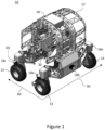
- Figures 1 and 2 show a mobile autonomous agricultural system 10 comprising a powered mobile unit 12.
- the mobile autonomous agricultural system 10 is configured to operate along rows 40 of crops (best shown in Figure 2 , with each row 40 shown extending into the page) to perform agricultural tasks, such as harvesting, husbandry, or monitoring the crops.
- the mobile unit 12 comprises an arch profile extending along an axial direction 50.
- a cross section of the mobile unit 12 comprises an arch profile.
- distal ends of arms of the arch are fixed to powered wheels 14 (which are pivotable with respect to the mobile unit 12 for steering) and extend away from the wheels 14 to an apex of the arch.
- each distal end of the arch is attached to two wheels 14, such that the whole arch is supported on the ground by a total of four wheels 14. It will be appreciated that in other examples, any suitable number of wheels may be used, or any other suitable device for propelling the mobile unit 12 may be used.
- the arch profile of the mobile unit 12 defines an inner zone 16, in the form of a tunnel extending along the axial direction 50, within which agricultural equipment 22 is disposed such that it is protected from damage.
- the agricultural equipment 22 in this example comprises robot arms. In other examples, it may include UV tubes or any other suitable equipment for carrying out agricultural tasks.
- the arch profile further allows the mobile unit 12 to traverse along rows 40 of crops, which are raised above the ground on posts (for ease of accessibility), with a single row 40 of crops extending through the inner zone 16 along the axial direction 50, and simultaneously accessible by the agricultural equipment from two sides of the row 40.
- the crops may be disposed on the ground, and the mobile unit may comprise any suitable profile to access the crops on the ground.
- the mobile autonomous agricultural system 10 comprises a controller 20 which is configured to control the travel of the mobile unit 12.
- the controller 20 in an autonomous mode, is configured to autonomously move the mobile unit 12 along the rows 40 of crops, and between the rows 40, where the rows may comprise a straight line of crops, or any other line of crops with a non-linear profile.
- the controller 20 is configured to align the axial direction 50 of the inner zone 16 of the mobile unit 12 with a first row 40 of crops such that the arch profile is centred and aligned with the row 40 of crops, and to move the mobile unit 12 to approach the first row 40, and continue to move the mobile unit 12 along the row 40, with the first row 40 received in the inner zone 16 until it reaches an end of the row 40.
- the controller 20 is configured to control the mobile unit 12 to exit the row 40, travel a predetermined distance away from the row 40, and traverse towards an adjacent row 40 to begin the process again with the adjacent row 40.
- the mobile autonomous agricultural system 10 may also be operated in a manual mode, in which a user can manually control the movement of the mobile unit 12, for example up to a first row 40, at which point the user may activate the autonomous mode.
- the autonomous mode of the mobile autonomous agricultural system 10 provides for autonomous movement between adjacent rows 40 of crops, in a single polytunnel of plants, and also from one polytunnel to another.
- the agricultural system 10 comprises a plurality of laser curtain sensors 18 distributed around the mobile unit 12.
- the laser curtain sensors 18 are each configured to project a respective laser plane towards the ground, and each laser plane overlaps with at least one other laser plane, so as together to form a laser curtain surrounding the mobile unit 12.
- Each laser curtain sensor 18 can detect when its respective laser plane is interrupted by sensing reflected waves of emitted laser beam light.
- the two side laser curtain sensors 18b project a laser plane close to vertically downwards such that the respective laser planes are not interrupted by the wheels 14 if the wheels are rotated by 90 degrees, and so that the respective laser planes are not interrupted by adjacent rows 40 when the mobile unit 12 is moving along a row 40. As is explained in more detail below, this helps to reduce the risk of erroneous generation of a safety output.
- the side laser curtains may be angled away from the mobile unit, or when the distance between the rows is narrow and constraining, and the wheels are smaller or do not rotate, then the side laser curtains may be angled towards the mobile unit.
- Each corner laser curtain sensor 18a is configured to project a laser plane angled downwards with respect to the horizontal to project away from the mobile unit 12, such that each laser plane from the corner laser curtain sensors 18a overlaps with the laser plane from an adjacent corner laser curtain sensor 18a, and so that the laser plane from each side laser curtain sensor 18b overlaps (or meets) with the laser planes from the adjacent corner laser curtain sensors 18a.
- laser curtain sensors 18 ensures that the mobile unit 12 is wholly surrounded by the laser curtain such that the presence of an object such as a person can be detected anywhere around the mobile unit 12. It will be appreciated that there may be any suitable number of laser sensors for the particular application of the mobile autonomous agricultural system, such as one laser curtain sensor, or more than one laser curtain sensor.
- the mobile autonomous agricultural system 10 further comprises a location module 24 which is configured to monitor a location of the mobile unit 12 relative to a row 40.
- the location module 24 may comprise GPS or any other suitable sensor which can be used to identify the location of the mobile unit relative to a row.
- the mobile autonomous agricultural system 10 further comprises a safety module 26 which is configured to receive a location signal from the location module 24, related to the location of the mobile unit 12 relative to a row 40, and to select a mode of operation based on the received location signal.
- Each mode of operation comprises processing the laser curtain in a different predefined laser curtain pattern to monitor interruptions to the laser curtain within the laser curtain pattern, as explained below with reference to Figures 3-7 .
- the safety module 26 is configured to generate a safety output in response to determining that the laser curtain is interrupted within the laser curtain pattern of the respective mode of operation. Therefore, any interruptions of the laser curtain outside the laser curtain pattern are ignored by the safety module.
- the safety output includes sending a signal to the controller to control the mobile unit 12 to stop, and to control the robot arms 22 to stop.
- the safety output bringing the mobile unit to instant halt when the laser curtain pattern is interrupted, and the laser curtain patterns changing between modes, provides the compliance to regulation legislated for use of an autonomous system where there are likely to be people in the vicinity, whilst improving operation capability for the mobile unit not to be erroneously halted by anything not related to people straying too close to the mobile unit.
- the safety output signal may be to slow the mobile unit or to slow the robot arms.
- the safety output may alternatively or additionally comprise producing an alarm, such as actuating an audible alarm on the mobile unit, or an alarm remote from the mobile unit to an operator, to alert the operator to the potential threat to safety of a person, or to alert the operator to the immobilising of the mobile unit or robot arms, such that they can restart the mobile unit or robot arms when it is determined to be safe again.
- an alarm such as actuating an audible alarm on the mobile unit, or an alarm remote from the mobile unit to an operator, to alert the operator to the potential threat to safety of a person, or to alert the operator to the immobilising of the mobile unit or robot arms, such that they can restart the mobile unit or robot arms when it is determined to be safe again.
- the location module, the safety module and the controller have been described as separate components, it will be appreciated that they can be incorporated into a single unit.
- the mobile unit may have any suitable profile, or the arch profile may be inverted so that a portion of the arch at the apex is fixed to wheels and the distal ends extend upwards, away from the wheels and the ground.
- This can be used in situations where the crops are suspended from above, such that an inner zone between arms of the arch receives the suspended crop, and the crop is accessible to agricultural equipment in the arch from two sides simultaneously.
- the axial direction may be the direction on the mobile unit which is configured to be parallel to a row while the controller controls the mobile unit to move along the row.
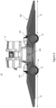
- Figures 3 and 4 show the mobile autonomous agricultural system 10 with a laser curtain pattern 100 in a default mode.
- the default mode is selected by the safety module 26 unless any deviating criteria are met.
- the default mode in this example is selected when the mobile unit 12 is outside the rows 40 of crops and is moving from a location at which it has been switched from the manual mode to the autonomous mode, and when the mobile unit 12 is moving from one polytunnel comprising rows 40 of crops to another polytunnel comprising rows 40 of crops. During these periods, no deviating criteria are met.
- the laser curtain pattern 100 in the default mode extends from each of the wheels 14, away from the mobile unit 12, in the axial direction 50 up to a maximum axial distance 30, which in this example is 2m.
- the laser curtain pattern 100 in the default mode also extends from each of the wheels 14, away from the mobile unit 12, in a width direction 60, which is perpendicular to the axial direction 50, up to a maximum width distance 32, which in this example is 2m.
- the safety module 26 determines that the laser curtain is interrupted within the laser curtain pattern 100 for the default mode, and generates the safety output.
- the maximum axial distance and the maximum width distance may be any suitable distance, such as between 1-3m.
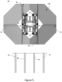
- Figure 5 shows the mobile autonomous agricultural system 10 with a laser curtain pattern 200 in a crabbing mode.
- the crabbing mode is selected by the safety module 26 when a first deviating criterion is met.
- the first deviating criterion comprises the mobile unit 12 being controlled to move, outside the rows 40 of crops, from one row 40 to align with another row 40.
- the laser curtain pattern 200 in the crabbing mode extends from the wheels 14 of the mobile unit 12, along the axial direction 50 up to a minimum axial distance 36, and in the width direction 60 up to the maximum width distance 32.
- the minimum axial distance 36 is 0.8m.
- the maximum width distance 32 is the same as for the default mode. Therefore, the laser curtain pattern 200 for the crabbing mode in this example is similar to the default mode except that the axial distance is shorter.
- the mobile unit 12 would only be moving in the width direction 60 (as shown in Figure 1 ) such that this direction is more critical, and requires a larger distance for the laser curtain pattern 200, whereas, there is no movement in the axial direction 50 (as shown in Figure 1 ) in the crabbing mode, such that the important safety feature is merely preventing entry to the inner zone 16 of the mobile unit 12 while it is operating.
- the axial and width extents may be different to suit other agricultural applications.
- Figure 6 shows the mobile autonomous agricultural system 10 with a laser curtain pattern 300 in an entry mode.
- the entry mode is selected by the safety module 26 when a second deviating criterion is met.
- the second deviating criterion comprising the mobile unit 12 being controlled to approach the rows 40, from outside the rows 40, and the signal from the location module 24 indicating that the mobile unit 12 is within a first threshold distance from an end of a row 40.
- the first threshold distance is the same as the maximum axial distance 30. In other examples, it will be appreciated that the threshold distance may be any suitable distance.
- the laser curtain pattern 300 in the entry mode extends from the wheels 14 of the mobile unit 12, along the axial direction 50 up to the maximum axial distance 30, and in the width direction 60 up to the maximum width distance 32 (i.e., with a similar pattern to the default mode).
- the laser curtain pattern 300 in the entry mode differs from that in the default mode by the laser curtain pattern 300 excluding at least one channel 38 from processing by the safety module 26, which channel 38 corresponds to the position of the row 40.
- This channel 38 ensures that the safety output from the safety module 26 is not erroneously generated by the posts and crops in the rows 40, whilst maintaining the laser curtain pattern 300 to surround the rest of the mobile unit 12, particularly between the mobile unit 12 and the rows 40, where there remains a risk of crushing a person therebetween.
- the channel 38 may be configured to grow dynamically based on the location of the mobile unit 12 relative to the row 40. For example, as the mobile unit 12 is entering a row 40, the channel is configured to grow to accommodate the row 40 whilst ensuring that the rest of the space between the end of the row 40 and the mobile unit 12 remains covered by the laser curtain pattern.
- the laser curtain pattern for the entry mode may be similar to the crabbing mode, and the first threshold distance may be the same as the minimum axial distance.
- the laser curtain pattern may have any suitable extents, whilst excluding at least one channel corresponding to the row.
- the entry mode may be similar to the default mode excluding the channel when the deviating criterion is met directly after the default mode has been active, and the entry mode may be similar to the crabbing mode excluding the channel when the deviating criterion is met directly after the crabbing mode has been active.
- Figure 7 shows the mobile autonomous agricultural system 10 with a laser curtain pattern 400 in a row mode.
- the row mode is selected by the safety module 26 when a third deviating criterion is met, the third deviating criterion comprising the mobile unit 12 being within a second threshold distance from an end of a row 40 or within the row 40 (i.e., with a row 40 received within the inner zone 16 of the mobile unit 12).
- the laser curtain pattern 400 in the row mode extends from the wheels 14 of the mobile unit 12, along the axial direction 50 up to the maximum axial distance 30, and in the width direction 60 up to a minimum width distance 42.
- the minimum width distance 42 takes the laser curtain pattern 400 up to the side laser curtain sensor 18b.
- the row mode therefore ensures that the safety output from the safety module 26 is not erroneously generated by the posts and crops in the rows 40, whilst maintaining the laser curtain pattern 300 to surround the rest of the mobile unit 12, in any direction in which a person could approach the mobile unit 12.
- the rows may be non-linear, and the modes may be configured to take account of this, and to dynamically change based on the configuration of the rows.
- the laser curtain patterns may be dependent on the specific shape of the mobile carrier, which may have different angles of approach for a person, and therefore different potential vulnerabilities in use.
- the laser curtain pattern also extends downwards from each of the laser curtain sensors 18 towards the ground (best shown in Figure 4 ) up to a threshold ground distance 34 from the ground.
- the threshold ground distance 34 is 20cm. Limiting the laser curtain pattern for each mode of operation up to the threshold ground distance 34 means that the mobile autonomous agricultural system 10 can be used on uneven ground, as the safety module 26 will not erroneously detect an interruption in the laser curtain pattern due to an uneven surface, whilst still triggering a safety output for a person who may attempt to crawl under, or may be lying prone on the ground.
- the threshold ground distance may be any distance between 10cm and 50cm. In other examples, there may be no threshold ground distance, such that the laser curtain pattern extends all the way to the ground.
- the laser curtain sensors 18 are also configured to monitor and map the ground surface, which may be uneven, undulating, or inclined.
- the laser curtain pattern for each mode of operation may be dynamically altered based on the mapped ground surface, for example, if it is determined that the inclination of the ground is above an inclination threshold, the laser curtain pattern may be dynamically altered to make the axial distance or the width distance for the respective mode of operation shorter.
- the laser curtain sensors are described as projecting a laser plane, it will be appreciated that the laser plane may be a single linear laser which is moved rapidly back and forth through a plane or about a pivot axis to form an effective laser plane. Further, although it is described that there are six laser curtain sensors, there may be any suitable number of laser curtain sensors, such as a single laser curtain sensor or more than one laser curtain sensor which are configured to project a laser curtain away from the mobile unit.
- the laser curtain patterns are described in specific examples above, it will be appreciated that any suitable laser curtain pattern may be used for each of the different modes of operation, and the laser curtain sensors can be angled at any suitable angle to ensure that the safety output is not erroneously generated.
- Figure 8 is a flow chart showing steps of a method 500 of controlling the powered mobile unit 12 of the mobile autonomous agricultural system 10.
- the method 500 comprises projecting the laser curtain away from the mobile unit 12 with the laser curtain sensors 18 to surround the mobile unit 12.
- the laser curtain may not surround the mobile unit, but may be placed, for example, in strategic positions.
- the method 500 comprises determining the location of the mobile unit 12 relative to a row 40, based on the signal from the location module 24.
- the safety module 26 may determine the mobile unit 12 to be in one of the following five locations, based on the location signal received from the location module 24 and optionally also a signal from the controller 20:
- the method 500 comprises determining whether any deviating criteria are met.
- the deviating criteria may include, for example, any of the first deviating criterion, the second deviating criterion and/or the third deviating criterion described with reference to Figures 5-7 . It will be appreciated that other deviating criteria may be applied.
- the method 500 proceeds to block 508, in which the default mode is selected, for example, as described with reference to Figures 3 and 4 .
- the method 500 proceeds to block 510 in which a mode other than the default mode is selected.
- a mode other than the default mode is selected depending on the deviating criterion which is met.
- the method 500 may select a crabbing mode as described with reference to Figure 5 , an entry mode as described with reference to Figure 6 , or a row mode as described with reference to Figure 7 .
- each mode of operation comprises a different laser curtain pattern which is configured to be processed.
- blocks 506-510 may comprise any suitable method for selecting different modes of operation based on the location of the mobile unit relative to a row. From both blocks 508 and 510 the method 500 proceeds to block 512, in which it is determined whether the laser curtain has been interrupted within the respective laser curtain pattern for the selected mode of operation.
- the method proceeds to block 514 which comprises generating a safety output such as sending a signal to control the mobile unit 12 to stop, or to control the robot arms to stop, or any other suitable safety output such as described above.
- a safety output such as sending a signal to control the mobile unit 12 to stop, or to control the robot arms to stop, or any other suitable safety output such as described above.
- the method 500 returns back to block 502 to start again. This method 500 is carried out continually to ensure the safety of users around the mobile unit 12.
Landscapes
- Engineering & Computer Science (AREA)
- Physics & Mathematics (AREA)
- Life Sciences & Earth Sciences (AREA)
- Environmental Sciences (AREA)
- Radar, Positioning & Navigation (AREA)
- Remote Sensing (AREA)
- General Physics & Mathematics (AREA)
- Automation & Control Theory (AREA)
- Aviation & Aerospace Engineering (AREA)
- Electromagnetism (AREA)
- Robotics (AREA)
- Computer Networks & Wireless Communication (AREA)
- Control Of Position, Course, Altitude, Or Attitude Of Moving Bodies (AREA)
- Guiding Agricultural Machines (AREA)
Claims (16)
- Mobiles autonomes landwirtschaftliches System (10), das Folgendes umfasst:eine angetriebene Mobileinheit (12) zum Tragen von landwirtschaftlicher Ausrüstung (22), die dazu ausgelegt ist, sich entlang von Reihen (40) von Erntegut zu bewegen;mindestens einen Laservorhangssensor (18), der dazu ausgelegt ist, einen Laservorhang von der Mobileinheit (12) weg zu projizieren;ein Standortmodul (24), das dazu ausgelegt ist, einen Standort der Mobileinheit (12) relativ zu einer Reihe (40) zu überwachen;eine Steuerung (20), die dazu ausgelegt ist, die Fahrt der Mobileinheit (12) zu steuern;ein Sicherheitsmodul (26), das zu Folgendem ausgelegt ist:Erzeugen eines Sicherheitsausgangs in Reaktion auf das Bestimmen, dass der Laservorhang innerhalb eines Laservorhangsmusters (100, 200, 300, 400) unterbrochen ist;dadurch gekennzeichnet, dass das Sicherheitsmodul zu Folgendem ausgelegt ist:Empfangen eines Standortsignals vom Standortmodul (24), das sich auf den Standort der Mobileinheit (12) relativ zu einer Reihe (40) bezieht, undAuswählen eines Betriebsmodus auf Basis des empfangenen Standortsignals, um den Laservorhang in einem vordefinierten Laservorhangsmuster (100, 200, 300, 400) zu verarbeiten, wobei jeder Betriebsmodus einem anderen vordefinierten Laservorhangsmuster (100, 200, 300, 400) entspricht.
- Mobiles autonomes landwirtschaftliches System (10) nach Anspruch 1, das eine Vielzahl von Laservorhangssensoren (18) umfasst, die um die Mobileinheit (12) verteilt und zusammen dazu ausgelegt sind, den Laservorhang zu bilden, und wahlweise wobei jeder Laservorhangssensor (18) dazu ausgelegt ist, eine jeweilige Laserebene zu projizieren, die sich mindestens mit einer weiteren Laserebene überlappt, um den Laservorhang zu bilden.
- Mobiles autonomes landwirtschaftliches System (10) nach Anspruch 2, wobei das Sicherheitsmodul (26) dazu ausgelegt ist, sofern keine abweichenden Kriterien erfüllt sind, einen Standardbetriebsmodus auszuwählen.
- Mobiles autonomes landwirtschaftliches System (10) nach Anspruch 3, wobei der Standardmodus das Verarbeiten des Laservorhangs in einem Laservorhangsmuster (100) umfasst, der sich von der Mobileinheit (12) in einer Axialrichtung (50) bis zu einem maximalen axialen Abstand (30) von der Mobileinheit (12) und in einer Breitenrichtung (60) senkrecht zur Axialrichtung (50) bis zu einem maximalen Breitenabstand (32) von der Mobileinheit (12) erstreckt.
- Mobiles autonomes landwirtschaftliches System (10) nach Anspruch 3 oder 4, wobei die abweichenden Kriterien ein erstes abweichendes Kriterium umfassen, das umfasst, dass die Mobileinheit (12) gesteuert wird, um sich von einer Reihe (40) zu einer anderen Reihe (40) zu bewegen, wobei, wenn das erste abweichende Kriterium erfüllt ist, der Sicherheitsmodus dazu ausgelegt ist, einen Krabbenmodus auszuwählen, und wahlweise
wobei der Krabbenmodus das Verarbeiten des Laservorhangs in einem Laservorhangsmuster (200) umfasst, der sich von der Mobileinheit (12) entlang der Axialrichtung (50) bis zu einem minimalen axialen Abstand (36) und in einer Breitenrichtung (60) senkrecht zur Axialrichtung (50) bis zu einem maximalen Breitenabstand (32) erstreckt. - Mobiles autonomes landwirtschaftliches System (10) nach einem der Ansprüche 3-5, wobei die abweichenden Kriterien ein zweites abweichendes Kriterium umfassen, das umfasst, dass die Mobileinheit (12) gesteuert wird, um sich einer Reihe (40) zu nähern, und das Bestimmen, dass sich die Mobileinheit (12) innerhalb eines ersten Schwellwertabstands von einem Ende der Reihe (40) befindet, derart, dass, wenn bestimmt wird, dass sich die Mobileinheit (12) innerhalb des ersten Schwellwertabstands von einem Ende einer Reihe (40) befindet, das Sicherheitsmodul (26) dazu ausgelegt ist, einen Eintrittsmodus auszuwählen, und wahlweise wobei der Eintrittsmodus das Verarbeiten des Laservorhangs im selben Maß wie der Standardmodus oder ein Krabbenmodus umfasst, das Verarbeiten eines Kanals (38) im Laservorhang, der der Position der Reihe (40) entspricht, aber ausschließt.
- Mobiles autonomes landwirtschaftliches System (10) nach einem der Ansprüche 3-6, wobei die abweichenden Kriterien ein drittes abweichendes Kriterium umfassen, das umfasst, dass sich die Mobileinheit (12) innerhalb eines zweiten Schwellwertabstands von einem Ende einer Reihe (40) oder innerhalb der Reihe (40) befindet, derart, dass, wenn das dritte abweichende Kriterium erfüllt ist, das Sicherheitsmodul (26) dazu ausgelegt ist, einen Reihen(40)-Modus auszuwählen, und wahlweise wobei der Reihen(40)-Modus das Verarbeiten des Laservorhangs zum Bilden eines Laservorhangsmusters (400) umfasst, der sich von der Mobileinheit (12) entlang der Axialrichtung (50) bis zu einem maximalen axialen Abstand (30) und in einer Breitenrichtung (60) senkrecht zur Axialrichtung (50) bis zu einem minimalen Breitenabstand (42) erstreckt.
- Mobiles autonomes landwirtschaftliches System (10) nach einem der vorhergehenden Ansprüche, wobei der Laservorhangssensor (18) dazu ausgelegt ist, die Bodenfläche zu überwachen und zu kartieren.
- Mobiles autonomes landwirtschaftliches System (10) nach Anspruch 8, wobei das Sicherheitsmodul (26) dazu ausgelegt ist, für jeden Betriebsmodus auf Basis der kartierten Bodenfläche das vordefinierte Laservorhangsmuster (100, 200, 300, 400) dynamisch zu ändern, und wahlweise
wobei, wenn der Laservorhangssensor (18) bestimmt, dass sich in der lokalen Bodenfläche um die Mobileinheit (12) eine über eine Schwellwertneigung hinausgehende Neigung befindet, das Sicherheitsmodul (26) dazu ausgelegt ist, das Laservorhangsmuster (100, 200, 300, 400), das durch Verkürzen einer axialen Erstreckung des Laservorhangsmusters (100, 200, 300, 400) oder einer Breitenerstreckung senkrecht zur Axialrichtung (50) verarbeitet wird, dynamisch zu ändern. - Verfahren (500) zum Steuern einer angetriebenen Mobileinheit (12) eines mobilen autonomen landwirtschaftlichen Systems (10) nach einem der vorhergehenden Ansprüche, wobei die Mobileinheit (12) dazu ausgelegt ist, landwirtschaftliche Ausrüstung (22) zu tragen, und dazu ausgelegt ist, sich entlang von Reihen (40) von Erntegut zu bewegen, wobei das Verfahren (500) Folgendes umfasst:Projizieren eines Laservorhangs von der Mobileinheit (12) weg;Bestimmen eines Standortes der Mobileinheit (12) relativ zu einer Reihe (40);Auswählen eines Betriebsmodus auf Basis des bestimmten Standortes der Mobileinheit (12) relativ zu der Reihe (40), um den Laservorhang in einem vordefinierten Laservorhangsmuster (100, 200, 300, 400) zu verarbeiten, wobei jeder Betriebsmodus das Verarbeiten eines anderen vordefinierten Laservorhangsmusters (100, 200, 300, 400) umfasst;Erzeugen eines Sicherheitsausgangs in Reaktion auf das Bestimmen, dass der Laservorhang innerhalb des Laservorhangsmusters (100, 200, 300, 400) unterbrochen ist.
- Verfahren (500) nach Anspruch 10, wobei der Laservorhang derart projiziert wird, dass er die Mobileinheit (12) umgibt.
- Verfahren (500) nach Anspruch 11, das das Auswählen eines Standardmodus umfasst, sofern keine abweichenden Kriterien erfüllt sind, und wahlweise
wobei der Standardmodus das Verarbeiten des Laservorhangs in einem Laservorhangsmuster (100) umfasst, der sich von der Mobileinheit (12) in einer Axialrichtung (50) bis zu einem maximalen axialen Abstand (30) von der Mobileinheit (12) und in einer Breitenrichtung (60) senkrecht zur Axialrichtung (50) bis zu einem maximalen Breitenabstand (32) von der Mobileinheit (12) erstreckt. - Verfahren (500) nach einem der Ansprüche 10-12, wobei sich für jeden Betriebsmodus jedes vordefinierte Laservorhangsmuster (100, 200, 300, 400), zu dessen Verarbeitung das Sicherheitsmodul (26) ausgelegt ist, bis zu einem Schwellwertbodenabstand (34) vom Boden erstreckt, wahlweise
wobei der Schwellwertabstand 10-50 cm vom Boden beträgt. - Verfahren (500) nach einem der Ansprüche 10-13, das das Überwachen und Kartieren der Bodenfläche und das dynamische Ändern des vordefinierten Laservorhangsmusters (100, 200, 300, 400) für jeden Betriebsmodus auf Basis der überwachten Bodenfläche umfasst und wahlweise
das Bestimmen auf Basis der kartierten Bodenfläche, dass sich in der Bodenfläche eine über einem Neigungsschwellwert liegende Neigung befindet und das dynamische Ändern des Laservorhangsmusters (100, 200, 300, 400) durch Verkürzen einer axialen Erstreckung des Laservorhangsmusters (100, 200, 300, 400) oder einer Breitenerstreckung senkrecht zur Axialrichtung (50) umfasst. - Computerprogramm, das computerlesbare Anweisungen umfasst, die, wenn sie von einer Steuerung eines mobilen autonomen landwirtschaftlichen Systems (10) gemäß den Ansprüchen 1-9 gelesen werden, die Durchführung eines Verfahrens (500) gemäß einem der Ansprüche 10-14 veranlassen.
- Nichttransitorisches computerlesbares Speichermedium, das das Computerprogramm nach Anspruch 15 umfasst.
Applications Claiming Priority (1)
| Application Number | Priority Date | Filing Date | Title |
|---|---|---|---|
| GB2112083.7A GB2610184B (en) | 2021-08-23 | 2021-08-23 | A mobile autonomous agricultural system and method |
Publications (3)
| Publication Number | Publication Date |
|---|---|
| EP4140288A1 EP4140288A1 (de) | 2023-03-01 |
| EP4140288B1 true EP4140288B1 (de) | 2024-10-02 |
| EP4140288C0 EP4140288C0 (de) | 2024-10-02 |
Family
ID=77914051
Family Applications (1)
| Application Number | Title | Priority Date | Filing Date |
|---|---|---|---|
| EP22191424.5A Active EP4140288B1 (de) | 2021-08-23 | 2022-08-22 | Mobiles autonomes landwirtschaftliches system und verfahren |
Country Status (6)
| Country | Link |
|---|---|
| US (2) | US12204339B2 (de) |
| EP (1) | EP4140288B1 (de) |
| AU (1) | AU2022221411B2 (de) |
| CA (1) | CA3171578C (de) |
| ES (1) | ES3009102T3 (de) |
| GB (1) | GB2610184B (de) |
Families Citing this family (6)
| Publication number | Priority date | Publication date | Assignee | Title |
|---|---|---|---|---|
| GB2616680A (en) * | 2022-03-18 | 2023-09-20 | S&A Group Holdings Ltd | A mobile autonomous agricultural system |
| CA225903S (en) * | 2023-05-31 | 2024-11-08 | S&A Group Holdings Ltd | An agricultural robot |
| GB2622459B (en) * | 2023-06-02 | 2024-10-30 | S&A Group Holdings Ltd | A mobile autonomous agricultural system |
| CA227607S (en) * | 2023-07-21 | 2024-12-16 | S&A Group Holdings Ltd | Shielding for an agricultural robot |
| EP4516089A1 (de) | 2023-08-29 | 2025-03-05 | S&A Group Holdings Limited | Ultraviolett-beleuchtung für ein mobiles autonomes landwirtschaftliches system |
| USD1096856S1 (en) * | 2024-10-04 | 2025-10-07 | Moray Tecnologia Ltda. | Agricultural vehicle |
Family Cites Families (10)
| Publication number | Priority date | Publication date | Assignee | Title |
|---|---|---|---|---|
| BR112016011577B1 (pt) * | 2013-11-20 | 2021-01-12 | Rowbot Systems Llc | plataforma de veículo autônomo, sistema de plataforma de veículo autônomo, robô agrícola e método para a navegação autônoma de um robô agrícola |
| CN120295312A (zh) * | 2016-08-26 | 2025-07-11 | 克朗设备公司 | 物料搬运车辆障碍物扫描工具 |
| KR102493698B1 (ko) * | 2017-01-20 | 2023-02-01 | 가부시끼 가이샤 구보다 | 작업차 |
| US10884115B2 (en) * | 2018-03-09 | 2021-01-05 | Waymo Llc | Tailoring sensor emission power to map, vehicle state, and environment |
| US12004451B2 (en) * | 2018-10-08 | 2024-06-11 | Advanced Farm Technologies, Inc. | Autonomous crop harvester |
| NL2022048B1 (en) * | 2018-11-22 | 2020-06-05 | Agxeed B V | Autonomous tractor and method to cultivate farmland using this tractor |
| JP7161976B2 (ja) * | 2019-06-20 | 2022-10-27 | ヤンマーパワーテクノロジー株式会社 | 作業車両用の自動走行システム |
| JP7356829B2 (ja) * | 2019-07-10 | 2023-10-05 | ヤンマーパワーテクノロジー株式会社 | 自動走行システム |
| FR3119964B1 (fr) * | 2021-02-22 | 2023-06-16 | Naio Tech | Robot agricole autonome |
| EP4108055B1 (de) * | 2021-06-22 | 2023-07-19 | Kubota Corporation | Landwirtschaftliche maschine |
-
2021
- 2021-08-23 GB GB2112083.7A patent/GB2610184B/en active Active
-
2022
- 2022-08-22 CA CA3171578A patent/CA3171578C/en active Active
- 2022-08-22 ES ES22191424T patent/ES3009102T3/es active Active
- 2022-08-22 EP EP22191424.5A patent/EP4140288B1/de active Active
- 2022-08-23 AU AU2022221411A patent/AU2022221411B2/en active Active
- 2022-08-23 US US17/893,758 patent/US12204339B2/en active Active
-
2024
- 2024-12-12 US US18/978,268 patent/US20250110498A1/en active Pending
Also Published As
| Publication number | Publication date |
|---|---|
| GB2610184B (en) | 2024-01-17 |
| AU2022221411B2 (en) | 2025-01-23 |
| EP4140288C0 (de) | 2024-10-02 |
| GB202112083D0 (en) | 2021-10-06 |
| CA3171578C (en) | 2026-02-24 |
| US20250110498A1 (en) | 2025-04-03 |
| US20230059246A1 (en) | 2023-02-23 |
| US12204339B2 (en) | 2025-01-21 |
| ES3009102T3 (en) | 2025-03-26 |
| EP4140288A1 (de) | 2023-03-01 |
| AU2022221411A1 (en) | 2023-03-09 |
| GB2610184A (en) | 2023-03-01 |
| CA3171578A1 (en) | 2023-02-23 |
Similar Documents
| Publication | Publication Date | Title |
|---|---|---|
| EP4140288B1 (de) | Mobiles autonomes landwirtschaftliches system und verfahren | |
| EP4114165B1 (de) | Führungssysteme und -verfahren | |
| US10231374B2 (en) | Travel support system, travel support method, and work vehicle | |
| JP7619527B2 (ja) | 自走式作業ロボット | |
| US11122740B2 (en) | Surroundings detection device for agricultural work machines | |
| US20190338492A1 (en) | Object Detection System and Method | |
| KR101573027B1 (ko) | 지능형 무인 제초 로봇 | |
| JP6411434B2 (ja) | 組み合わされた作業プラットフォーム/システム | |
| EP3165406B1 (de) | Traktor mit sichtsystem | |
| EP3794921A1 (de) | Rasenmäherroboter und entsprechendes verfahren | |
| US12582019B2 (en) | Mobile autonomous agricultural system | |
| US20240276909A1 (en) | Automatic lawn mower | |
| JP2016187305A (ja) | 移動農機 | |
| JP7191147B2 (ja) | 走行支援システム及び作業車 | |
| GB2497577A (en) | Linkage control systems for agricultural tractor | |
| JP2000023507A (ja) | 走行作業車 | |
| WO2025234273A1 (ja) | 切断箇所決定プログラム、切断箇所決定装置、及び収穫装置 | |
| WO2025234269A1 (ja) | 収穫ロボット | |
| WO2025234268A1 (ja) | 連結システムおよび連結プログラム | |
| KR20230171703A (ko) | 자율이동 무인 방제기와 그 운용방법, 그리고 자율 레일전환 이동 제어방법 | |
| CN121219113A (zh) | 自动化工作空间监测的机器人装置和方法 | |
| WO2025234267A1 (ja) | 位置特定システムおよび位置特定プログラム | |
| WO2025234270A1 (ja) | 農作物収穫システムおよび農作物収穫プログラム | |
| JP2009078336A (ja) | 複数ロボットの干渉防止制御装置および干渉防止制御方法 |
Legal Events
| Date | Code | Title | Description |
|---|---|---|---|
| PUAI | Public reference made under article 153(3) epc to a published international application that has entered the european phase |
Free format text: ORIGINAL CODE: 0009012 |
|
| STAA | Information on the status of an ep patent application or granted ep patent |
Free format text: STATUS: THE APPLICATION HAS BEEN PUBLISHED |
|
| AK | Designated contracting states |
Kind code of ref document: A1 Designated state(s): AL AT BE BG CH CY CZ DE DK EE ES FI FR GB GR HR HU IE IS IT LI LT LU LV MC MK MT NL NO PL PT RO RS SE SI SK SM TR |
|
| STAA | Information on the status of an ep patent application or granted ep patent |
Free format text: STATUS: REQUEST FOR EXAMINATION WAS MADE |
|
| 17P | Request for examination filed |
Effective date: 20230313 |
|
| RBV | Designated contracting states (corrected) |
Designated state(s): AL AT BE BG CH CY CZ DE DK EE ES FI FR GB GR HR HU IE IS IT LI LT LU LV MC MK MT NL NO PL PT RO RS SE SI SK SM TR |
|
| GRAP | Despatch of communication of intention to grant a patent |
Free format text: ORIGINAL CODE: EPIDOSNIGR1 |
|
| STAA | Information on the status of an ep patent application or granted ep patent |
Free format text: STATUS: GRANT OF PATENT IS INTENDED |
|
| INTG | Intention to grant announced |
Effective date: 20231016 |
|
| GRAJ | Information related to disapproval of communication of intention to grant by the applicant or resumption of examination proceedings by the epo deleted |
Free format text: ORIGINAL CODE: EPIDOSDIGR1 |
|
| STAA | Information on the status of an ep patent application or granted ep patent |
Free format text: STATUS: REQUEST FOR EXAMINATION WAS MADE |
|
| INTC | Intention to grant announced (deleted) | ||
| GRAP | Despatch of communication of intention to grant a patent |
Free format text: ORIGINAL CODE: EPIDOSNIGR1 |
|
| STAA | Information on the status of an ep patent application or granted ep patent |
Free format text: STATUS: GRANT OF PATENT IS INTENDED |
|
| INTG | Intention to grant announced |
Effective date: 20240328 |
|
| GRAS | Grant fee paid |
Free format text: ORIGINAL CODE: EPIDOSNIGR3 |
|
| GRAA | (expected) grant |
Free format text: ORIGINAL CODE: 0009210 |
|
| STAA | Information on the status of an ep patent application or granted ep patent |
Free format text: STATUS: THE PATENT HAS BEEN GRANTED |
|
| RBV | Designated contracting states (corrected) |
Designated state(s): AL AT BE BG CH CY CZ DE DK EE ES FI FR GR HR HU IE IS IT LI LT LU LV MC MK MT NL NO PL PT RO RS SE SI SK SM TR |
|
| AK | Designated contracting states |
Kind code of ref document: B1 Designated state(s): AL AT BE BG CH CY CZ DE DK EE ES FI FR GR HR HU IE IS IT LI LT LU LV MC MK MT NL NO PL PT RO RS SE SI SK SM TR |
|
| REG | Reference to a national code |
Ref country code: CH Ref legal event code: EP |
|
| REG | Reference to a national code |
Ref country code: IE Ref legal event code: FG4D |
|
| REG | Reference to a national code |
Ref country code: DE Ref legal event code: R096 Ref document number: 602022006485 Country of ref document: DE |
|
| U01 | Request for unitary effect filed |
Effective date: 20241022 |
|
| U07 | Unitary effect registered |
Designated state(s): AT BE BG DE DK EE FI FR IT LT LU LV MT NL PT RO SE SI Effective date: 20241106 |
|
| REG | Reference to a national code |
Ref country code: ES Ref legal event code: FG2A Ref document number: 3009102 Country of ref document: ES Kind code of ref document: T3 Effective date: 20250326 |
|
| PG25 | Lapsed in a contracting state [announced via postgrant information from national office to epo] |
Ref country code: IS Free format text: LAPSE BECAUSE OF FAILURE TO SUBMIT A TRANSLATION OF THE DESCRIPTION OR TO PAY THE FEE WITHIN THE PRESCRIBED TIME-LIMIT Effective date: 20250202 Ref country code: HR Free format text: LAPSE BECAUSE OF FAILURE TO SUBMIT A TRANSLATION OF THE DESCRIPTION OR TO PAY THE FEE WITHIN THE PRESCRIBED TIME-LIMIT Effective date: 20241002 |
|
| PG25 | Lapsed in a contracting state [announced via postgrant information from national office to epo] |
Ref country code: GR Free format text: LAPSE BECAUSE OF FAILURE TO SUBMIT A TRANSLATION OF THE DESCRIPTION OR TO PAY THE FEE WITHIN THE PRESCRIBED TIME-LIMIT Effective date: 20250103 |
|
| PG25 | Lapsed in a contracting state [announced via postgrant information from national office to epo] |
Ref country code: PL Free format text: LAPSE BECAUSE OF FAILURE TO SUBMIT A TRANSLATION OF THE DESCRIPTION OR TO PAY THE FEE WITHIN THE PRESCRIBED TIME-LIMIT Effective date: 20241002 Ref country code: CZ Free format text: LAPSE BECAUSE OF FAILURE TO SUBMIT A TRANSLATION OF THE DESCRIPTION OR TO PAY THE FEE WITHIN THE PRESCRIBED TIME-LIMIT Effective date: 20241002 |
|
| PG25 | Lapsed in a contracting state [announced via postgrant information from national office to epo] |
Ref country code: RS Free format text: LAPSE BECAUSE OF FAILURE TO SUBMIT A TRANSLATION OF THE DESCRIPTION OR TO PAY THE FEE WITHIN THE PRESCRIBED TIME-LIMIT Effective date: 20250102 |
|
| PG25 | Lapsed in a contracting state [announced via postgrant information from national office to epo] |
Ref country code: SM Free format text: LAPSE BECAUSE OF FAILURE TO SUBMIT A TRANSLATION OF THE DESCRIPTION OR TO PAY THE FEE WITHIN THE PRESCRIBED TIME-LIMIT Effective date: 20241002 |
|
| PG25 | Lapsed in a contracting state [announced via postgrant information from national office to epo] |
Ref country code: SK Free format text: LAPSE BECAUSE OF FAILURE TO SUBMIT A TRANSLATION OF THE DESCRIPTION OR TO PAY THE FEE WITHIN THE PRESCRIBED TIME-LIMIT Effective date: 20241002 |
|
| PLBE | No opposition filed within time limit |
Free format text: ORIGINAL CODE: 0009261 |
|
| STAA | Information on the status of an ep patent application or granted ep patent |
Free format text: STATUS: NO OPPOSITION FILED WITHIN TIME LIMIT |
|
| 26N | No opposition filed |
Effective date: 20250703 |
|
| U20 | Renewal fee for the european patent with unitary effect paid |
Year of fee payment: 4 Effective date: 20250827 |
|
| PGFP | Annual fee paid to national office [announced via postgrant information from national office to epo] |
Ref country code: ES Payment date: 20250903 Year of fee payment: 4 |
|
| PGFP | Annual fee paid to national office [announced via postgrant information from national office to epo] |
Ref country code: NO Payment date: 20250814 Year of fee payment: 4 |
|
| PGFP | Annual fee paid to national office [announced via postgrant information from national office to epo] |
Ref country code: IE Payment date: 20250815 Year of fee payment: 4 |
|
| REG | Reference to a national code |
Ref country code: CH Ref legal event code: H13 Free format text: ST27 STATUS EVENT CODE: U-0-0-H10-H13 (AS PROVIDED BY THE NATIONAL OFFICE) Effective date: 20260324 |