EP4139625B1 - Vorrichtung zum abfeuern einer pistole - Google Patents
Vorrichtung zum abfeuern einer pistole Download PDFInfo
- Publication number
- EP4139625B1 EP4139625B1 EP21720263.9A EP21720263A EP4139625B1 EP 4139625 B1 EP4139625 B1 EP 4139625B1 EP 21720263 A EP21720263 A EP 21720263A EP 4139625 B1 EP4139625 B1 EP 4139625B1
- Authority
- EP
- European Patent Office
- Prior art keywords
- striker
- springs
- slide
- pistol according
- axis
- Prior art date
- Legal status (The legal status is an assumption and is not a legal conclusion. Google has not performed a legal analysis and makes no representation as to the accuracy of the status listed.)
- Active
Links
Images
Classifications
-
- F—MECHANICAL ENGINEERING; LIGHTING; HEATING; WEAPONS; BLASTING
- F41—WEAPONS
- F41A—FUNCTIONAL FEATURES OR DETAILS COMMON TO BOTH SMALLARMS AND ORDNANCE, e.g. CANNONS; MOUNTINGS FOR SMALLARMS OR ORDNANCE
- F41A19/00—Firing or trigger mechanisms; Cocking mechanisms
- F41A19/06—Mechanical firing mechanisms, e.g. counterrecoil firing, recoil actuated firing mechanisms
- F41A19/13—Percussion or firing pins, i.e. fixed or slidably-mounted striker elements; Mountings therefor
-
- F—MECHANICAL ENGINEERING; LIGHTING; HEATING; WEAPONS; BLASTING
- F41—WEAPONS
- F41A—FUNCTIONAL FEATURES OR DETAILS COMMON TO BOTH SMALLARMS AND ORDNANCE, e.g. CANNONS; MOUNTINGS FOR SMALLARMS OR ORDNANCE
- F41A19/00—Firing or trigger mechanisms; Cocking mechanisms
- F41A19/06—Mechanical firing mechanisms, e.g. counterrecoil firing, recoil actuated firing mechanisms
- F41A19/25—Mechanical firing mechanisms, e.g. counterrecoil firing, recoil actuated firing mechanisms having only slidably-mounted striker elements, i.e. percussion or firing pins
- F41A19/27—Mechanical firing mechanisms, e.g. counterrecoil firing, recoil actuated firing mechanisms having only slidably-mounted striker elements, i.e. percussion or firing pins the percussion or firing pin being movable relative to the breech-block
- F41A19/29—Mechanical firing mechanisms, e.g. counterrecoil firing, recoil actuated firing mechanisms having only slidably-mounted striker elements, i.e. percussion or firing pins the percussion or firing pin being movable relative to the breech-block propelled by a spring under tension
- F41A19/30—Mechanical firing mechanisms, e.g. counterrecoil firing, recoil actuated firing mechanisms having only slidably-mounted striker elements, i.e. percussion or firing pins the percussion or firing pin being movable relative to the breech-block propelled by a spring under tension in bolt-action guns
-
- F—MECHANICAL ENGINEERING; LIGHTING; HEATING; WEAPONS; BLASTING
- F41—WEAPONS
- F41C—SMALLARMS, e.g. PISTOLS, RIFLES; ACCESSORIES THEREFOR
- F41C3/00—Pistols, e.g. revolvers
Definitions
- the present invention relates to a pistol percussion device.
- pistol firing devices consist of either a hammer producing a shock at the rear of a firing pin whose front end strikes the primer of a chambered round, or a pre-cocked firing pin set in motion by a compressed spring when the weapon is loaded.
- the spring In the case of pre-cocked firing pins, the spring must be able to store enough energy to ensure a safe strike, while occupying a reduced space, particularly in relation to the longitudinal axis of the pistol.
- the percussion spring In order to allow a balanced movement of the firing pin, the percussion spring is generally arranged concentrically to the axis of the firing pin, either around it or inside it. The firing pin then serves as a guide for the spring to reduce the risk of buckling during compression.
- the reliability of the firing device is directly linked to the amount of energy stored in the firing pin spring, and given the constraints mentioned above it is difficult to increase this in the devices of the prior art except to the detriment of the size of the device.
- WO03/081160 discloses a striker actuated by a single spring arranged laterally and parallel to the striker.
- the invention relates to a gun according to claim 1.
- lateral we mean that the axes of the springs are parallel and arranged either above or below, or to the left or right.
- the at least two springs and the corresponding support surfaces are arranged symmetrically around the axis of the striker.
- symmetrical we mean in this description any type of symmetry, including rotational symmetries, so that the torques applied by the at least two springs cancel each other out: it may be two springs arranged symmetrically on either side of the axis or rotational symmetry of order 3 (3 springs located on a circle at angles separated by 120°).
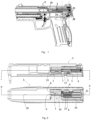
- the present invention relates to a pistol comprising a firing device in which the percussion energy is provided by at least two firing pin springs 4, 6 arranged symmetrically on either side of the axis of the firing pin 20, unlike the prior art where a single spring arranged concentrically to the axis is used.
- the use of several springs adapted in length and working in parallel allows the use of a lower stiffness to guarantee the same level energy. This is to also reduce the energy required to provide for the "racking" of the weapon (manual recocking).
- the stiffness of the percussion springs being lower, it is therefore possible to reduce the effort of the recoil spring sized so as to put the slide in battery and tension the percussion springs.
- the invention thus also allows an improvement in the general ergonomics of the weapon and its service life.
- the mass of the firing pin is between 1.5 and 6g, preferably between 2 and 3g.
- the striker comprises at least two symmetrical recesses 13 on either side of its axis 20 to accommodate the at least two springs 4, 6. These recesses make it possible to reduce the total weight of the striker and to reduce the torque generated by each spring by bringing it closer to the axis of the striker.
- the thrust of the spring is only exerted on part of the stroke of the firing pin.
- the end of its forward stroke is then carried out without contact with the spring.
- a weak return spring makes it possible to push the firing pin out of the bottom of the cup.
- the vertical movement of the cartridge during unlocking can then be done without rubbing on the firing pin and therefore without risking breaking it.
- the free stroke of the firing pin is generally achieved by adding components, which goes in the direction of increased complexity and an increase in the price of the weapon.
- the percussion springs 4, 6 after an initial stroke pushed by the springs, the percussion springs 4, 6 no longer press on the firing pin but against a stop surface 22 of a housing in the slide 5 accommodating the firing device of the invention.
- the firing pin then travels freely from this point.
- a lightweight firing pin then allows the use of a very weak firing pin return spring and therefore having little impact on the percussion energy stored in the system, the return spring being placed in opposition to the percussion springs.
- the slide is the most expensive component of the pistol.
- a significant reduction in its price can be achieved by using a plastic housing that eliminates costly machining operations in the slide.
- said housing is provided in a casing 24 fixed to the slide 5.
- said casing 24 is made of polymer while the remainder of the slide is essentially metallic.
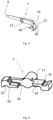
- said striker 1 and said at least two springs 4, 6 are pre-assembled in said housing 24, said springs being held in position by a spring support 21 comprising at least two spring guides inserted inside said springs 4, 6.
- the striker 1 is preferably guided over its entire travel in a channel 29 formed in the metal part of the slide 5 opening into the bottom of the bowl 23. The guidance is then done via a shaft or rod supporting the striker head 9 in a bore opening into the bottom of the bowl 23.
- the slide is essentially metallic and the striker 1 comprises a rod supporting the striker head 9 sliding in a cylindrical guide duct for the striker 1 formed in the metal of the slide 5.
- the pistol further comprises a firing pin safety device integrated into the slide 5, the firing pin 1 comprising a lateral extension 25 comprising two safety lugs 10, 11 and a firing pin safety butterfly 2 arranged on an axis of rotation 27 fixed to the slide and parallel to the axis of translation of the firing pin 20, said safety butterfly 2 being able to rotate in a vertical plane between a firing position and a blocking position, said butterfly 25 comprising two bearing surfaces 17, 18 on which said lugs 10, 11 rest when said butterfly is in the blocking position and two recesses 14 being able to allow said lugs 10, 11 to pass when said butterfly is in the firing position, the center of mass of said butterfly 2 being on its axis of rotation 27 and the axis of rotation 27 being a main axis of inertia of said butterfly.
- butterfly 2 comprising a lateral extension 25 comprising two safety lugs 10, 11 and a firing pin safety butterfly 2 arranged on an axis of rotation 27 fixed to the slide and parallel to the axis of translation of the firing pin 20, said safety butterfly
- the butterfly 2 is actuated in rotation by a safety control trigger 30, itself actuated by the firing control chain controlled by a trigger tail.
Landscapes
- Engineering & Computer Science (AREA)
- General Engineering & Computer Science (AREA)
- Toys (AREA)
- Portable Nailing Machines And Staplers (AREA)
Claims (13)
- Pistole, umfassend eine Zündvorrichtung, die in einer Gleitführung (5) angeordnet ist, die besagte Vorrichtung umfassend einen Schlagbolzen (1), umfassend einen Schlagbolzenkopf (9), dadurch gekennzeichnet, dass der besagte Schlagbolzen (1) mindestens zwei Anlageflächen (12) umfasst, die senkrecht zu der Achse (20) des Schlagbolzens (1) angeordnet sind, und dass die besagte Vorrichtung mindestens zwei Schlagbolzenfedern (4,6) , die parallel und seitlich auf der Seite der Schlagbolzenachse (20) angeordnet sind und an den mindestens zwei Anlageflächen (12) anliegen, umfasst.
- Pistole nach Anspruch 1, wobei die mindestens zwei Federn und die entsprechenden Anlageflächen symmetrisch um die Achse des Schlagbolzens angeordnet sind.
- Pistole nach Anspruch 1 oder 2, wobei der Schlagbolzen (1) mindestens zwei Aussparungen (13), die um seine Achse (20) angeordnet sind, um die mindestens zwei Federn (4, 6) aufzunehmen umfasst.
- Pistole nach einem der vorherigen Ansprüche, wobei die mindestens zwei Schlagbolzenfedern (4, 6) zwei Schlagbolzenfedern (4, 6) sind, die auf beiden Seiten der Schlagbolzenachse (20) angeordnet sind.
- Pistole nach einem der vorherigen Ansprüche, wobei die besagte Schlagbolzenfedern (4, 6) und der besagte Schlagbolzen (1) in einer Aufnahme einer Gleitführung (5) angeordnet sind, die besagte Aufnahme umfassend eine Anschlagfläche (22) der Schlagbolzenfedern (4, 6), die es ermöglicht, den Druck der Federn (4,6) auf die Anlageflächen (12) des Schlagbolzens (1) vor dem Auftauchen des Schlagbolzenkopfs (9) aus einem Wannenboden (23) der Gleitschiene zu ermöglichen, um einen freien Lauf des Schlagbolzens (1) am Ende der Schlagbewegung und eine Rückkehr in eine hintere Ruheposition des ruhenden Schlagbolzens ohne Auftauchen aus dem Wannenboden zu ermöglichen.
- Pistole nach Anspruch 5, wobei in der besagten Aufnahme der Gleitführung (5) eine Rückholfeder (19), die an der Gleitführung (5) anliegt und eine nach hinten gerichtete Kraft auf den Schlagbolzen (1) ausübt angeordnet ist.
- Pistole nach irgendeinem der vorherigen Ansprüche, wobei die Masse des Schlagbolzens zwischen 1,5 und 6g, vorzugsweise zwischen 2 und 3g, liegt.
- Pistole nach einem der Ansprüche 5 oder 6, wobei die besagte Aufnahme in einem Gehäuse (24) ausgebildet ist, das an der Gleitführung (5) befestigt ist.
- Pistole nach Anspruch 8, wobei das besagte Gehäuse (24) aus Polymer ist.
- Pistole nach einem der Ansprüche 8 oder 9, wobei der besagte Schlagbolzen (1) und die besagten mindestens zwei Federn (4, 6) in dem Gehäuse (24) vormontiert sind, wobei die besagte Federn durch einen Federhalter (21), umfassend mindestens zwei Federführungen, die in das Innere der Federn (4, 6) eingreifen, in Position gehalten werden.
- Pistole nach irgendeinem der vorherigen Ansprüche, wobei die Gleitführung im Wesentlichen aus Metall ist und der Schlagbolzen (1) eine Haltestange des Schlagbolzenkopfs (9), die in einem Führungskanal des Schlagbolzen (1), der in dem Metall der Gleitführung (5) ausgebildet ist, gleitet, umfasst.
- Pistole nach einem der vorherigen Ansprüche, wobei die besagte mindestens zwei Federn (4, 6), deren jeweilige Achsen parallel zueinander sind, Federn vom Kompressionstyp sind.
- Pistole nach Anspruch 12, wobei die jeweiligen Achsen der besagten mindestens zwei Federn und die Achse des Schlagbolzens koplanair sind.
Priority Applications (1)
| Application Number | Priority Date | Filing Date | Title |
|---|---|---|---|
| HRP20241664TT HRP20241664T1 (hr) | 2020-04-23 | 2021-04-21 | Naprava za opaljivanje za pištolj |
Applications Claiming Priority (2)
| Application Number | Priority Date | Filing Date | Title |
|---|---|---|---|
| EP20171208.0A EP3901556A1 (de) | 2020-04-23 | 2020-04-23 | Vorrichtung zum abfeuern einer pistole |
| PCT/EP2021/060339 WO2021214118A1 (fr) | 2020-04-23 | 2021-04-21 | Dispositif de mise à feu d'un pistolet |
Publications (2)
| Publication Number | Publication Date |
|---|---|
| EP4139625A1 EP4139625A1 (de) | 2023-03-01 |
| EP4139625B1 true EP4139625B1 (de) | 2024-09-18 |
Family
ID=70470809
Family Applications (2)
| Application Number | Title | Priority Date | Filing Date |
|---|---|---|---|
| EP20171208.0A Withdrawn EP3901556A1 (de) | 2020-04-23 | 2020-04-23 | Vorrichtung zum abfeuern einer pistole |
| EP21720263.9A Active EP4139625B1 (de) | 2020-04-23 | 2021-04-21 | Vorrichtung zum abfeuern einer pistole |
Family Applications Before (1)
| Application Number | Title | Priority Date | Filing Date |
|---|---|---|---|
| EP20171208.0A Withdrawn EP3901556A1 (de) | 2020-04-23 | 2020-04-23 | Vorrichtung zum abfeuern einer pistole |
Country Status (8)
| Country | Link |
|---|---|
| US (1) | US11913743B2 (de) |
| EP (2) | EP3901556A1 (de) |
| BR (1) | BR112022021403A2 (de) |
| FI (1) | FI4139625T3 (de) |
| HR (1) | HRP20241664T1 (de) |
| IL (1) | IL297516B1 (de) |
| PL (1) | PL4139625T3 (de) |
| WO (1) | WO2021214118A1 (de) |
Family Cites Families (10)
| Publication number | Priority date | Publication date | Assignee | Title |
|---|---|---|---|---|
| NL77664C (de) * | 1945-07-14 | |||
| US5081780A (en) * | 1990-12-14 | 1992-01-21 | Colt's Manufacturing Company Inc. | Firing pin positioning system |
| US5517896A (en) * | 1994-11-07 | 1996-05-21 | Perrine; Walter E. | Semi-automatic handgun with independent firing spring |
| US6688210B2 (en) * | 2002-03-27 | 2004-02-10 | Wilhelm Bubits | Pistol with a firing bolt firing mechanism |
| EP2228616B1 (de) * | 2009-03-12 | 2011-06-29 | SIG SAUER GmbH | Abzugsmechanismus für Handfeuerwaffen |
| US8356543B2 (en) * | 2009-10-02 | 2013-01-22 | Defense Deisigns, LLC | Firearm firing mechanism |
| US9546843B2 (en) * | 2013-11-06 | 2017-01-17 | Taurus International Manufacturing, Inc. | Extendable slide member for pistol slide |
| US9303936B2 (en) * | 2014-01-13 | 2016-04-05 | Sig Sauer, Inc. | Frame assembly for striker-fired pistol |
| US10739095B2 (en) * | 2015-12-01 | 2020-08-11 | Mean L.L.C. | Firearm operating system |
| DE102019000301B4 (de) * | 2019-01-18 | 2022-12-22 | Gerhard Kirstein | Halbautomatische oder vollautomatische Feuerwaffe |
-
2020
- 2020-04-23 EP EP20171208.0A patent/EP3901556A1/de not_active Withdrawn
-
2021
- 2021-04-21 WO PCT/EP2021/060339 patent/WO2021214118A1/fr not_active Ceased
- 2021-04-21 HR HRP20241664TT patent/HRP20241664T1/hr unknown
- 2021-04-21 BR BR112022021403A patent/BR112022021403A2/pt active Search and Examination
- 2021-04-21 PL PL21720263.9T patent/PL4139625T3/pl unknown
- 2021-04-21 US US17/996,918 patent/US11913743B2/en active Active
- 2021-04-21 FI FIEP21720263.9T patent/FI4139625T3/fi active
- 2021-04-21 EP EP21720263.9A patent/EP4139625B1/de active Active
-
2022
- 2022-10-22 IL IL297516A patent/IL297516B1/en unknown
Also Published As
| Publication number | Publication date |
|---|---|
| US20230175799A1 (en) | 2023-06-08 |
| FI4139625T3 (fi) | 2024-12-11 |
| BR112022021403A2 (pt) | 2022-12-13 |
| IL297516A (en) | 2022-12-01 |
| EP4139625A1 (de) | 2023-03-01 |
| EP3901556A1 (de) | 2021-10-27 |
| PL4139625T3 (pl) | 2025-02-17 |
| HRP20241664T1 (hr) | 2025-02-14 |
| WO2021214118A1 (fr) | 2021-10-28 |
| IL297516B1 (en) | 2026-01-01 |
| US11913743B2 (en) | 2024-02-27 |
Similar Documents
| Publication | Publication Date | Title |
|---|---|---|
| EP0274957B1 (de) | Setzgerät mit Treibkolben | |
| EP0573093B1 (de) | Vorrichtung zum Bremsen des Rückstossschlittens einer Feuerwaffe | |
| EP3722544A1 (de) | Griffsystem mit sicherheitsvorrichtung | |
| EP2285534B1 (de) | Werzeug zum anbringen von drahtgewindeeinsätzen mit verriegelungskeil und kit mit diesem werkzeug | |
| EP2402706A1 (de) | Sicherheits- und Zündvorrichtung mit Trägheitsschloss in MEMS-Technologien | |
| EP3901554B1 (de) | Abzugssicherung einer pistole | |
| EP4139625B1 (de) | Vorrichtung zum abfeuern einer pistole | |
| EP2482027B1 (de) | Sicherheits- und Zündvorrichtung für eine pyrotechnische Kette eines Geschosses | |
| FR2535045A1 (fr) | Projectile declencheur d'avalanches | |
| EP0018870B1 (de) | Setzgerät mit einem Schlagbolzen | |
| FR2989014A1 (fr) | Dispositif de montage de fixations a forte interference | |
| EP1559638A2 (de) | Scharniere für eine Motorhaube und dazu gehörende Hebevorrichtung | |
| EP2445684B1 (de) | Bolzensetzwerkzeug, im besonderen für unterwasserarbeiten | |
| FR2622495A1 (fr) | Appareil de scellement a extracteur perfectionne | |
| EP0633449B1 (de) | Sicherungs- und Scharfsvorrichtung für explosive Gegenständen | |
| FR2783598A1 (fr) | Arme a tube de gros calibre | |
| EP3901555A1 (de) | Schlagbolzensicherung einer pistole | |
| EP1557341A1 (de) | Vorrichtung zum Festhalten einer Fahrzeugmotorhaube | |
| EP0260204A1 (de) | Gasdruckbetätigtes automatisches Gewehr, z.B. Kipplaufgewehr | |
| BE527942A (de) | ||
| FR2778976A1 (fr) | Dispositif de percussion d'une carabine a culasse fixe | |
| BE420605A (de) | ||
| BE334396A (de) | ||
| BE510865A (de) | ||
| BE549417A (de) |
Legal Events
| Date | Code | Title | Description |
|---|---|---|---|
| REG | Reference to a national code |
Ref country code: HR Ref legal event code: TUEP Ref document number: P20241664T Country of ref document: HR |
|
| STAA | Information on the status of an ep patent application or granted ep patent |
Free format text: STATUS: UNKNOWN |
|
| STAA | Information on the status of an ep patent application or granted ep patent |
Free format text: STATUS: THE INTERNATIONAL PUBLICATION HAS BEEN MADE |
|
| PUAI | Public reference made under article 153(3) epc to a published international application that has entered the european phase |
Free format text: ORIGINAL CODE: 0009012 |
|
| STAA | Information on the status of an ep patent application or granted ep patent |
Free format text: STATUS: REQUEST FOR EXAMINATION WAS MADE |
|
| 17P | Request for examination filed |
Effective date: 20221114 |
|
| AK | Designated contracting states |
Kind code of ref document: A1 Designated state(s): AL AT BE BG CH CY CZ DE DK EE ES FI FR GB GR HR HU IE IS IT LI LT LU LV MC MK MT NL NO PL PT RO RS SE SI SK SM TR |
|
| DAV | Request for validation of the european patent (deleted) | ||
| DAX | Request for extension of the european patent (deleted) | ||
| STAA | Information on the status of an ep patent application or granted ep patent |
Free format text: STATUS: EXAMINATION IS IN PROGRESS |
|
| 17Q | First examination report despatched |
Effective date: 20231006 |
|
| GRAP | Despatch of communication of intention to grant a patent |
Free format text: ORIGINAL CODE: EPIDOSNIGR1 |
|
| STAA | Information on the status of an ep patent application or granted ep patent |
Free format text: STATUS: GRANT OF PATENT IS INTENDED |
|
| INTG | Intention to grant announced |
Effective date: 20240418 |
|
| GRAS | Grant fee paid |
Free format text: ORIGINAL CODE: EPIDOSNIGR3 |
|
| P01 | Opt-out of the competence of the unified patent court (upc) registered |
Free format text: CASE NUMBER: APP_40099/2024 Effective date: 20240705 |
|
| GRAA | (expected) grant |
Free format text: ORIGINAL CODE: 0009210 |
|
| STAA | Information on the status of an ep patent application or granted ep patent |
Free format text: STATUS: THE PATENT HAS BEEN GRANTED |
|
| AK | Designated contracting states |
Kind code of ref document: B1 Designated state(s): AL AT BE BG CH CY CZ DE DK EE ES FI FR GB GR HR HU IE IS IT LI LT LU LV MC MK MT NL NO PL PT RO RS SE SI SK SM TR |
|
| REG | Reference to a national code |
Ref country code: GB Ref legal event code: FG4D Free format text: NOT ENGLISH |
|
| REG | Reference to a national code |
Ref country code: CH Ref legal event code: EP |
|
| REG | Reference to a national code |
Ref country code: DE Ref legal event code: R096 Ref document number: 602021018975 Country of ref document: DE |
|
| REG | Reference to a national code |
Ref country code: IE Ref legal event code: FG4D Free format text: LANGUAGE OF EP DOCUMENT: FRENCH |
|
| REG | Reference to a national code |
Ref country code: FI Ref legal event code: FGE |
|
| REG | Reference to a national code |
Ref country code: LT Ref legal event code: MG9D |
|
| PG25 | Lapsed in a contracting state [announced via postgrant information from national office to epo] |
Ref country code: NO Free format text: LAPSE BECAUSE OF FAILURE TO SUBMIT A TRANSLATION OF THE DESCRIPTION OR TO PAY THE FEE WITHIN THE PRESCRIBED TIME-LIMIT Effective date: 20241218 |
|
| PG25 | Lapsed in a contracting state [announced via postgrant information from national office to epo] |
Ref country code: GR Free format text: LAPSE BECAUSE OF FAILURE TO SUBMIT A TRANSLATION OF THE DESCRIPTION OR TO PAY THE FEE WITHIN THE PRESCRIBED TIME-LIMIT Effective date: 20241219 |
|
| PG25 | Lapsed in a contracting state [announced via postgrant information from national office to epo] |
Ref country code: BG Free format text: LAPSE BECAUSE OF FAILURE TO SUBMIT A TRANSLATION OF THE DESCRIPTION OR TO PAY THE FEE WITHIN THE PRESCRIBED TIME-LIMIT Effective date: 20240918 |
|
| PG25 | Lapsed in a contracting state [announced via postgrant information from national office to epo] |
Ref country code: LV Free format text: LAPSE BECAUSE OF FAILURE TO SUBMIT A TRANSLATION OF THE DESCRIPTION OR TO PAY THE FEE WITHIN THE PRESCRIBED TIME-LIMIT Effective date: 20240918 |
|
| REG | Reference to a national code |
Ref country code: NL Ref legal event code: MP Effective date: 20240918 |
|
| PG25 | Lapsed in a contracting state [announced via postgrant information from national office to epo] |
Ref country code: RS Free format text: LAPSE BECAUSE OF FAILURE TO SUBMIT A TRANSLATION OF THE DESCRIPTION OR TO PAY THE FEE WITHIN THE PRESCRIBED TIME-LIMIT Effective date: 20241218 |
|
| PG25 | Lapsed in a contracting state [announced via postgrant information from national office to epo] |
Ref country code: RS Free format text: LAPSE BECAUSE OF FAILURE TO SUBMIT A TRANSLATION OF THE DESCRIPTION OR TO PAY THE FEE WITHIN THE PRESCRIBED TIME-LIMIT Effective date: 20241218 Ref country code: NO Free format text: LAPSE BECAUSE OF FAILURE TO SUBMIT A TRANSLATION OF THE DESCRIPTION OR TO PAY THE FEE WITHIN THE PRESCRIBED TIME-LIMIT Effective date: 20241218 Ref country code: LV Free format text: LAPSE BECAUSE OF FAILURE TO SUBMIT A TRANSLATION OF THE DESCRIPTION OR TO PAY THE FEE WITHIN THE PRESCRIBED TIME-LIMIT Effective date: 20240918 Ref country code: GR Free format text: LAPSE BECAUSE OF FAILURE TO SUBMIT A TRANSLATION OF THE DESCRIPTION OR TO PAY THE FEE WITHIN THE PRESCRIBED TIME-LIMIT Effective date: 20241219 Ref country code: BG Free format text: LAPSE BECAUSE OF FAILURE TO SUBMIT A TRANSLATION OF THE DESCRIPTION OR TO PAY THE FEE WITHIN THE PRESCRIBED TIME-LIMIT Effective date: 20240918 |
|
| REG | Reference to a national code |
Ref country code: HR Ref legal event code: T1PR Ref document number: P20241664 Country of ref document: HR |
|
| PG25 | Lapsed in a contracting state [announced via postgrant information from national office to epo] |
Ref country code: NL Free format text: LAPSE BECAUSE OF FAILURE TO SUBMIT A TRANSLATION OF THE DESCRIPTION OR TO PAY THE FEE WITHIN THE PRESCRIBED TIME-LIMIT Effective date: 20240918 |
|
| PG25 | Lapsed in a contracting state [announced via postgrant information from national office to epo] |
Ref country code: IS Free format text: LAPSE BECAUSE OF FAILURE TO SUBMIT A TRANSLATION OF THE DESCRIPTION OR TO PAY THE FEE WITHIN THE PRESCRIBED TIME-LIMIT Effective date: 20250118 Ref country code: PT Free format text: LAPSE BECAUSE OF FAILURE TO SUBMIT A TRANSLATION OF THE DESCRIPTION OR TO PAY THE FEE WITHIN THE PRESCRIBED TIME-LIMIT Effective date: 20250120 |
|
| PG25 | Lapsed in a contracting state [announced via postgrant information from national office to epo] |
Ref country code: RO Free format text: LAPSE BECAUSE OF FAILURE TO SUBMIT A TRANSLATION OF THE DESCRIPTION OR TO PAY THE FEE WITHIN THE PRESCRIBED TIME-LIMIT Effective date: 20240918 Ref country code: SM Free format text: LAPSE BECAUSE OF FAILURE TO SUBMIT A TRANSLATION OF THE DESCRIPTION OR TO PAY THE FEE WITHIN THE PRESCRIBED TIME-LIMIT Effective date: 20240918 |
|
| PG25 | Lapsed in a contracting state [announced via postgrant information from national office to epo] |
Ref country code: ES Free format text: LAPSE BECAUSE OF FAILURE TO SUBMIT A TRANSLATION OF THE DESCRIPTION OR TO PAY THE FEE WITHIN THE PRESCRIBED TIME-LIMIT Effective date: 20240918 |
|
| PG25 | Lapsed in a contracting state [announced via postgrant information from national office to epo] |
Ref country code: EE Free format text: LAPSE BECAUSE OF FAILURE TO SUBMIT A TRANSLATION OF THE DESCRIPTION OR TO PAY THE FEE WITHIN THE PRESCRIBED TIME-LIMIT Effective date: 20240918 |
|
| PG25 | Lapsed in a contracting state [announced via postgrant information from national office to epo] |
Ref country code: SK Free format text: LAPSE BECAUSE OF FAILURE TO SUBMIT A TRANSLATION OF THE DESCRIPTION OR TO PAY THE FEE WITHIN THE PRESCRIBED TIME-LIMIT Effective date: 20240918 |
|
| REG | Reference to a national code |
Ref country code: HR Ref legal event code: ODRP Ref document number: P20241664 Country of ref document: HR Payment date: 20250414 Year of fee payment: 5 |
|
| REG | Reference to a national code |
Ref country code: DE Ref legal event code: R097 Ref document number: 602021018975 Country of ref document: DE |
|
| PGFP | Annual fee paid to national office [announced via postgrant information from national office to epo] |
Ref country code: FI Payment date: 20250425 Year of fee payment: 5 |
|
| PGFP | Annual fee paid to national office [announced via postgrant information from national office to epo] |
Ref country code: DE Payment date: 20250429 Year of fee payment: 5 |
|
| PG25 | Lapsed in a contracting state [announced via postgrant information from national office to epo] |
Ref country code: DK Free format text: LAPSE BECAUSE OF FAILURE TO SUBMIT A TRANSLATION OF THE DESCRIPTION OR TO PAY THE FEE WITHIN THE PRESCRIBED TIME-LIMIT Effective date: 20240918 |
|
| PGFP | Annual fee paid to national office [announced via postgrant information from national office to epo] |
Ref country code: GB Payment date: 20250428 Year of fee payment: 5 |
|
| PGFP | Annual fee paid to national office [announced via postgrant information from national office to epo] |
Ref country code: BE Payment date: 20250428 Year of fee payment: 5 Ref country code: IT Payment date: 20250422 Year of fee payment: 5 |
|
| PGFP | Annual fee paid to national office [announced via postgrant information from national office to epo] |
Ref country code: HR Payment date: 20250414 Year of fee payment: 5 |
|
| PGFP | Annual fee paid to national office [announced via postgrant information from national office to epo] |
Ref country code: FR Payment date: 20250425 Year of fee payment: 5 |
|
| PGFP | Annual fee paid to national office [announced via postgrant information from national office to epo] |
Ref country code: CH Payment date: 20250501 Year of fee payment: 5 |
|
| PGFP | Annual fee paid to national office [announced via postgrant information from national office to epo] |
Ref country code: AT Payment date: 20250721 Year of fee payment: 5 |
|
| PLBE | No opposition filed within time limit |
Free format text: ORIGINAL CODE: 0009261 |
|
| STAA | Information on the status of an ep patent application or granted ep patent |
Free format text: STATUS: NO OPPOSITION FILED WITHIN TIME LIMIT |
|
| PGFP | Annual fee paid to national office [announced via postgrant information from national office to epo] |
Ref country code: CZ Payment date: 20250407 Year of fee payment: 5 |
|
| 26N | No opposition filed |
Effective date: 20250619 |
|
| PG25 | Lapsed in a contracting state [announced via postgrant information from national office to epo] |
Ref country code: SE Free format text: LAPSE BECAUSE OF FAILURE TO SUBMIT A TRANSLATION OF THE DESCRIPTION OR TO PAY THE FEE WITHIN THE PRESCRIBED TIME-LIMIT Effective date: 20240918 |
|
| PG25 | Lapsed in a contracting state [announced via postgrant information from national office to epo] |
Ref country code: LU Free format text: LAPSE BECAUSE OF NON-PAYMENT OF DUE FEES Effective date: 20250421 |
|
| PG25 | Lapsed in a contracting state [announced via postgrant information from national office to epo] |
Ref country code: MC Free format text: LAPSE BECAUSE OF FAILURE TO SUBMIT A TRANSLATION OF THE DESCRIPTION OR TO PAY THE FEE WITHIN THE PRESCRIBED TIME-LIMIT Effective date: 20240918 |