EP4137892B1 - Blendenartige auslösevorrichtung, insbesondere für uhrwerke - Google Patents
Blendenartige auslösevorrichtung, insbesondere für uhrwerke Download PDFInfo
- Publication number
- EP4137892B1 EP4137892B1 EP21192337.0A EP21192337A EP4137892B1 EP 4137892 B1 EP4137892 B1 EP 4137892B1 EP 21192337 A EP21192337 A EP 21192337A EP 4137892 B1 EP4137892 B1 EP 4137892B1
- Authority
- EP
- European Patent Office
- Prior art keywords
- rigid
- armature
- deformable
- configuration
- portions
- Prior art date
- Legal status (The legal status is an assumption and is not a legal conclusion. Google has not performed a legal analysis and makes no representation as to the accuracy of the status listed.)
- Active
Links
Images


Classifications
-
- G—PHYSICS
- G04—HOROLOGY
- G04B—MECHANICALLY-DRIVEN CLOCKS OR WATCHES; MECHANICAL PARTS OF CLOCKS OR WATCHES IN GENERAL; TIME PIECES USING THE POSITION OF THE SUN, MOON OR STARS
- G04B45/00—Time pieces of which the indicating means or cases provoke special effects, e.g. aesthetic effects
- G04B45/02—Time pieces of which the clockwork is visible partly or wholly
-
- G—PHYSICS
- G02—OPTICS
- G02B—OPTICAL ELEMENTS, SYSTEMS OR APPARATUS
- G02B5/00—Optical elements other than lenses
- G02B5/005—Diaphragms
-
- G—PHYSICS
- G04—HOROLOGY
- G04B—MECHANICALLY-DRIVEN CLOCKS OR WATCHES; MECHANICAL PARTS OF CLOCKS OR WATCHES IN GENERAL; TIME PIECES USING THE POSITION OF THE SUN, MOON OR STARS
- G04B17/00—Mechanisms for stabilising frequency
- G04B17/20—Compensation of mechanisms for stabilising frequency
- G04B17/28—Compensation of mechanisms for stabilising frequency for the effect of imbalance of the weights, e.g. tourbillon
- G04B17/285—Tourbillons or carrousels
-
- G—PHYSICS
- G04—HOROLOGY
- G04B—MECHANICALLY-DRIVEN CLOCKS OR WATCHES; MECHANICAL PARTS OF CLOCKS OR WATCHES IN GENERAL; TIME PIECES USING THE POSITION OF THE SUN, MOON OR STARS
- G04B27/00—Mechanical devices for setting the time indicating means
- G04B27/004—Mechanical devices for setting the time indicating means having several simultaneous functions, e.g. stopping or starting the clockwork or the hands
-
- G—PHYSICS
- G03—PHOTOGRAPHY; CINEMATOGRAPHY; ANALOGOUS TECHNIQUES USING WAVES OTHER THAN OPTICAL WAVES; ELECTROGRAPHY; HOLOGRAPHY
- G03B—APPARATUS OR ARRANGEMENTS FOR TAKING PHOTOGRAPHS OR FOR PROJECTING OR VIEWING THEM; APPARATUS OR ARRANGEMENTS EMPLOYING ANALOGOUS TECHNIQUES USING WAVES OTHER THAN OPTICAL WAVES; ACCESSORIES THEREFOR
- G03B9/00—Exposure-making shutters; Diaphragms
- G03B9/02—Diaphragms
- G03B9/06—Two or more co-operating pivoted blades, e.g. iris type
-
- G—PHYSICS
- G04—HOROLOGY
- G04B—MECHANICALLY-DRIVEN CLOCKS OR WATCHES; MECHANICAL PARTS OF CLOCKS OR WATCHES IN GENERAL; TIME PIECES USING THE POSITION OF THE SUN, MOON OR STARS
- G04B19/00—Indicating the time by visual means
- G04B19/06—Dials
- G04B19/16—Shiftable dials, e.g. indicating alternately from 1 to 12 and from 13 to 24
-
- G—PHYSICS
- G04—HOROLOGY
- G04F—TIME-INTERVAL MEASURING
- G04F7/00—Apparatus for measuring unknown time intervals by non-electric means
- G04F7/04—Apparatus for measuring unknown time intervals by non-electric means using a mechanical oscillator
- G04F7/08—Watches or clocks with stop devices, e.g. chronograph
- G04F7/0823—Watches or clocks with stop devices, e.g. chronograph with couplings between the chronograph mechanism and the base movement
- G04F7/0828—Watches or clocks with stop devices, e.g. chronograph with couplings between the chronograph mechanism and the base movement acting in the plane of the movement
Definitions
- the invention relates to a diaphragm-type deployment device, particularly for watchmaking.
- the invention also relates to a timepiece comprising such a deployment device.
- Diaphragm-type deployment devices are elements having a frame that can transform from a compact configuration, in which the device has a reduced volume or geometry, to an expanded configuration, in which the device has a larger volume or geometry.
- These devices are often used in watchmaking, particularly in display devices or in drive devices, or even for locking the rotation axis of a wheel.
- display devices they may serve as a removable screen to conceal a portion or all of information presented by the display device.
- the information In the compact configuration, the information is uncovered so as to be visible, for example, by the wearer of a watch comprising the display device, while in the extended configuration, the device covers the information.
- Examples of display devices are shown in the documents CH46061 , CH711228 , DE29521914 , DE1985554 Or EP1842112 .
- the document EP3671370 shows a deployment device for coupling two superimposed rotating elements.
- the two elements are coupled by the deployment device in contact with the two elements so that one of the elements drives the other element in rotation.
- the two elements are decoupled, so that the rotation of one no longer drives the rotation of the other.
- the invention aims to remedy the aforementioned drawbacks, and aims to provide a diaphragm-type deployment device, the manufacture of which is simplified and less expensive.
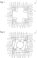
- the invention relates to a diaphragm-type deployment device, in particular for watchmaking, the deployment device comprising a first rigid frame and a second deformable frame, the first rigid frame and the second deformable frame being connected to each other, so that the second deformable frame passes from a first extended configuration to a second compact configuration, and vice versa, the device defining a first geometry when the second frame is in the first extended configuration, and defining a second geometry smaller than the first geometry, when the second frame is in the second configuration compact, the device extending substantially in the same plane when the second frame is in the first or second configuration.
- the deployment device is remarkable in that at least a first part of the first rigid frame and at least a first part of the second deformable frame form a first single-piece assembly, preferably made from the same material.
- the device according to the invention manufacturing costs are reduced, and diaphragm-type deployment devices can be manufactured more quickly, and which can be smaller.
- the entirety of the first rigid frame and the entirety of the second deformable frame form the first single-piece assembly.
- a second part of the first rigid frame and a second part of the second deformable frame form a second single-piece assembly.
- the first set and the second set are superimposed on each other.
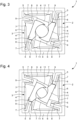
- the second deformable frame comprises at least two movable flaps, preferably four movable flaps, the flaps being distributed by angular symmetry.
- the shutters delimit the first opening of the first configuration and the second opening of the second configuration.
- the material of the device is to be chosen from silicon, a nickel-phosphorus alloy of the Ni/P type, a steel alloy of the Fe/Ni/Co/Mo type.
- the second deformable frame comprises first deformable portions and rigid portions assembled alternately.
- a first deformable portion connects a rigid portion to a following rigid portion.
- the second deformable frame comprises second deformable portions connecting one rigid portion out of two to the first rigid frame.
- the rigid portions connected to the first rigid frame have different shapes from the other rigid portions.
- each deformable portion comprises a flexible blade connecting by its ends two rigid portions, or a rigid portion and the first rigid frame.
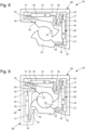
- the device comprises means for moving at least one rigid portion, preferably several rigid portions, in order to pass the second frame from the extended configuration to the compact configuration and vice versa.
- the rigid portion(s) moved by the moving means are rigid portions connected to the first rigid frame.
- the rigid portion(s) moved by the moving means are rigid portions which are not connected to the first rigid frame.
- the displacement means are configured to produce a substantially rectilinear displacement of the rigid portion(s).
- the displacement means are configured to produce a rotary displacement of the rigid portion(s).
- the rigid portions connected to the first rigid frame undergo a rotary movement around a pivot point when the second frame passes from the extended configuration to the compact configuration and vice versa.
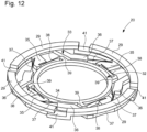
- the second deformable frame delimits the external perimeter of the diaphragm, the first rigid frame being arranged inside said perimeter.
- the first rigid frame delimits the external perimeter of the diaphragm, the second frame being arranged inside said perimeter.
- the first geometry defines a first opening when the second deformable frame is in the first extended configuration
- the second geometry defines a second opening, when the second deformable frame is in the second compact configuration, the first opening being narrower than the second opening
- each flap is arranged on a different rigid portion of the second deformable frame.
- the present invention is defined by the appended claim 1 and is not limited to the illustrated examples but is susceptible to various variants and modifications which will appear to those skilled in the art.
- the diaphragm forms for example a cam whose geometry is variable.
- the flexible blades can also have a bar shape with flexible necks, or be replaced by a combination of blades, which can be crossed or straight, or even be replaced by a flexible element.
Landscapes
- Physics & Mathematics (AREA)
- General Physics & Mathematics (AREA)
- Optics & Photonics (AREA)
- Micromachines (AREA)
- Electric Clocks (AREA)
- Tents Or Canopies (AREA)
Claims (24)
- Entfaltungsvorrichtung (1, 10, 20) vom Typ Blende, insbesondere für die Uhrmacherei, wobei die Vorrichtung ein erstes starres Gerüst (2, 12, 32) und ein zweites verformbares Gerüst (3, 13, 33) beinhaltet, wobei das erste starre Gerüst (2, 12, 32) und das zweite verformbare Gerüst (3, 13, 33) miteinander verbunden sind, sodass das zweite verformbare Gerüst (3, 13, 33) von einer ersten ausgebreiteten Konfiguration in eine zweite kompakte Konfiguration übergeht und umgekehrt, wobei die Vorrichtung (1, 10, 20) eine erste Geometrie definiert, wenn das zweite verformbare Gerüst (3, 13, 33) in der ersten ausgebreiteten Konfiguration ist, und eine zweite, kleinere Geometrie als die erste Geometrie definiert, wenn das zweite verformbare Gerüst (3, 13, 33) in der zweiten kompakten Konfiguration ist, wobei sich die Vorrichtung (1, 10, 20) im Wesentlichen in einer gleichen Ebene erstreckt, wenn das zweite Gerüst in der ersten oder in der zweiten Konfiguration ist, dadurch gekennzeichnet, dass mindestens ein erster Teil des ersten starren Gerüstes (2, 12, 32) und mindestens ein erster Teil des zweiten verformbaren Gerüstes (3, 13, 33) eine erste einteilige Baugruppe, vorzugsweise aus einem gleichen Material, bilden.
- Vorrichtung nach Anspruch 1, dadurch gekennzeichnet, dass die Gesamtheit des ersten starren Gerüstes (2, 12, 32) und die Gesamtheit des zweiten verformbaren Gerüstes (3, 13, 33) die erste einteilige Baugruppe bilden.
- Vorrichtung nach Anspruch 1, dadurch gekennzeichnet, dass ein zweiter Teil des ersten starren Gerüstes (2, 12, 32) und ein zweiter Teil des zweiten verformbaren Gerüstes (3, 13, 33) eine zweite einteilige Baugruppe bilden.
- Vorrichtung nach Anspruch 3, dadurch gekennzeichnet, dass die erste Baugruppe und die zweite Baugruppe übereinander liegen.
- Vorrichtung nach einem der Ansprüche 1 bis 4, dadurch gekennzeichnet, dass das erste starre Gerüst (2, 12) den äußeren Umfang der Blende begrenzt, wobei das zweite verformbare Gerüst (3, 13) innerhalb des Umfangs angeordnet ist.
- Vorrichtung nach Anspruch 5, dadurch gekennzeichnet, dass die erste Geometrie eine erste Öffnung definiert, wenn das zweite verformbare Gerüst (3, 13) in der ersten ausgebreiteten Konfiguration ist, und die zweite Geometrie eine zweite Öffnung definiert, wenn das zweite verformbare Gerüst (3, 13) in der zweiten kompakten Konfiguration ist, wobei die erste Öffnung enger als die zweite Öffnung ist.
- Vorrichtung nach Anspruch 5 oder 6, dadurch gekennzeichnet, dass das zweite verformbare Gerüst (3, 13, 33) mindestens zwei bewegliche Klappen, vorzugsweise vier bewegliche Klappen, umfasst, wobei die Klappen winkelsymmetrisch verteilt sind.
- Vorrichtung nach den Ansprüchen 6 und 7, dadurch gekennzeichnet, dass die Klappen (11, 21) die erste Öffnung der ersten Konfiguration und die zweite Öffnung der zweiten Konfiguration begrenzen.
- Vorrichtung nach einem der Ansprüche 1 bis 4, dadurch gekennzeichnet, dass das zweite verformbare Gerüst (33) den äußeren Umfang der Blende begrenzt, wobei das erste starre Gerüst (32) innerhalb des Umfangs angeordnet ist.
- Vorrichtung nach Anspruch 9, dadurch gekennzeichnet, dass die erste Geometrie einen ersten Umfang definiert, wenn das zweite verformbare Gerüst (33) in der ersten ausgebreiteten Konfiguration ist, und die zweite Geometrie einen zweiten Umfang definiert, wenn das zweite verformbare Gerüst (33) in der zweiten kompakten Konfiguration ist, wobei der erste Umfang größer als der zweite Umfang ist.
- Vorrichtung nach Anspruch 10, dadurch gekennzeichnet, dass das zweite verformbare Gerüst (33) mindestens einen Schuh (29), vorzugsweise vier Schuhe (29) umfasst, die es ermöglichen, den variablen Umfang der Vorrichtung (20) zu begrenzen, wobei jeder Schuh (29) auf einem anderen starren Abschnitt (35) des zweiten verformbaren Gerüstes (33) angeordnet ist.
- Vorrichtung nach einem der vorstehenden Ansprüche, dadurch gekennzeichnet, dass das zweite verformbare Gerüst (3, 13, 33) erste verformbare Abschnitte (7, 17, 37) und starre Abschnitte (5, 6, 15, 16, 35, 36) umfasst, die abwechselnd zusammengesetzt sind, wobei ein erster verformbarer Abschnitt einen starren Abschnitt (5, 6, 15, 16, 35, 36) mit einem nachfolgenden starren Abschnitt (5, 6, 15, 16, 35, 36) verbindet.
- Vorrichtung nach Anspruch 12, dadurch gekennzeichnet, dass das zweite verformbare Gerüst (3, 13, 33) zweite verformbare Abschnitte (8, 18, 38) umfasst, die jeden zweiten starren Abschnitt (5, 15, 35) mit dem ersten starren Gerüst (2, 12, 32) verbinden.
- Vorrichtung nach Anspruch 13, dadurch gekennzeichnet, dass die starren Abschnitte (5, 15, 35), die mit dem ersten starren Gerüst (2, 12, 32) verbunden sind, andere Formen als die anderen starren Abschnitte (6, 16, 36) aufweisen.
- Vorrichtung nach einem der Ansprüche 12 bis 14, dadurch gekennzeichnet, dass jeder verformbare Abschnitt (7, 8, 17, 18, 37, 38) eine flexible Klinge umfasst, die an ihren Enden zwei starre Abschnitte (5, 6, 15, 16, 35, 36) oder einen starren Abschnitt (5, 15, 35) und das erste starre Gerüst (2, 12, 32) verbindet.
- Vorrichtung nach einem der Ansprüche 12 bis 15, dadurch gekennzeichnet, dass sie Mittel zum Verschieben mindestens eines starren Abschnitts (6, 16, 35), vorzugsweise mehrerer starrer Abschnitte (6, 16, 35), umfasst, um das zweite verformbare Gerüst (3, 13, 33) von der ausgebreiteten Konfiguration in die kompakte Konfiguration übergehen zu lassen, und umgekehrt.
- Vorrichtung nach Anspruch 16, dadurch gekennzeichnet, dass der oder die starren Abschnitte (35), die von den Mitteln zum Verschieben verschoben werden, starre Abschnitte (35) sind, die mit dem ersten starren Gerüst (32) verbunden sind.
- Vorrichtung Anspruch 16, dadurch gekennzeichnet, dass der oder die starren Abschnitte (6, 16), die von den Mittel zum Verschieben verschoben werden, starre Abschnitte (6, 16) sind, die nicht mit dem ersten starren Gerüst (32) verbunden sind.
- Vorrichtung nach Anspruch 18, dadurch gekennzeichnet, dass die Mittel zum Verschieben konfiguriert sind, um eine im Wesentlichen geradlinige Verschiebung des oder der starren Abschnitte (6, 16) zu erzeugen.
- Vorrichtung nach Anspruch 17, dadurch gekennzeichnet, dass die Mittel zum Verschieben konfiguriert sind, um eine Drehverschiebung des oder der starren Abschnitte (35) zu erzeugen.
- Vorrichtung nach einem der Ansprüche 16 bis 20, dadurch gekennzeichnet, dass die starren Abschnitte (5, 15, 35), die mit dem ersten starren Gerüst (2, 12, 32) verbunden sind, einer Drehverschiebung um einen Schwenkpunkt herum unterliegen, wenn das zweite verformbare Gerüst (3, 13, 33) von der ausgebreiteten Konfiguration in die kompakte Konfiguration übergeht und umgekehrt.
- Vorrichtung nach Anspruch 7 und einem der Ansprüche 12 bis 21, wobei jede Klappe (11, 21) auf einem anderen starren Abschnitt (5, 15) des zweiten verformbaren Gerüstes (3, 13) angeordnet ist.
- Vorrichtung nach einem der vorstehenden Ansprüche, wobei das Material der Vorrichtung (1, 10, 20) aus Silizium, einer Nickel-Phosphor-Legierung vom Typ Ni/P oder einer Stahllegierung vom Typ Fe/Ni/Co/Mo auszuwählen ist.
- Uhrmachereistück, dadurch gekennzeichnet, dass es eine Entfaltungsvorrichtung (1, 10, 20) vom Typ Blende nach einem der vorstehenden Ansprüche umfasst.
Priority Applications (4)
| Application Number | Priority Date | Filing Date | Title |
|---|---|---|---|
| EP21192337.0A EP4137892B1 (de) | 2021-08-20 | 2021-08-20 | Blendenartige auslösevorrichtung, insbesondere für uhrwerke |
| US17/815,708 US20230057054A1 (en) | 2021-08-20 | 2022-07-28 | Diaphragm type deployment device, particularly for watchmaking |
| JP2022129168A JP7515542B2 (ja) | 2021-08-20 | 2022-08-15 | 特に腕時計製造用のダイヤフラムタイプの展開デバイス |
| CN202210999705.3A CN115903431B (zh) | 2021-08-20 | 2022-08-19 | 用于制表的膜片型展开装置 |
Applications Claiming Priority (1)
| Application Number | Priority Date | Filing Date | Title |
|---|---|---|---|
| EP21192337.0A EP4137892B1 (de) | 2021-08-20 | 2021-08-20 | Blendenartige auslösevorrichtung, insbesondere für uhrwerke |
Publications (2)
| Publication Number | Publication Date |
|---|---|
| EP4137892A1 EP4137892A1 (de) | 2023-02-22 |
| EP4137892B1 true EP4137892B1 (de) | 2025-04-02 |
Family
ID=77431185
Family Applications (1)
| Application Number | Title | Priority Date | Filing Date |
|---|---|---|---|
| EP21192337.0A Active EP4137892B1 (de) | 2021-08-20 | 2021-08-20 | Blendenartige auslösevorrichtung, insbesondere für uhrwerke |
Country Status (4)
| Country | Link |
|---|---|
| US (1) | US20230057054A1 (de) |
| EP (1) | EP4137892B1 (de) |
| JP (1) | JP7515542B2 (de) |
| CN (1) | CN115903431B (de) |
Families Citing this family (1)
| Publication number | Priority date | Publication date | Assignee | Title |
|---|---|---|---|---|
| EP4137893A1 (de) * | 2021-08-20 | 2023-02-22 | Montres Breguet S.A. | Blendenartige auslösevorrichtung, insbesondere für uhrwerke |
Family Cites Families (21)
| Publication number | Priority date | Publication date | Assignee | Title |
|---|---|---|---|---|
| CH46061A (fr) | 1909-01-26 | 1910-01-17 | Ulysse Borel | Montre avec diaphragme iris |
| FR1362611A (fr) * | 1963-04-12 | 1964-06-05 | Dispositif électro-mécanique de commande des sonneries pour pendules, horloges et autres mécanismes d'horlogerie et systèmes similaires | |
| JPS636377U (de) * | 1986-06-26 | 1988-01-16 | ||
| CH679969B5 (de) * | 1990-12-11 | 1992-11-30 | Ebauchesfabrik Eta Ag | |
| DE29521914U1 (de) | 1995-01-18 | 1998-11-26 | Tönjes, Günter, 49205 Hasbergen | Uhr |
| CH698500B1 (fr) | 2005-01-24 | 2009-08-31 | Christophe Claret Sa | Pièce d'horlogerie à cadran muni d'une ouverture. |
| WO2012010408A1 (fr) * | 2010-07-19 | 2012-01-26 | Nivarox-Far S.A. | Mecanisme oscillant a pivot elastique et mobile de transmission d'energie |
| CH703464B1 (fr) * | 2010-07-19 | 2013-11-29 | Nivarox Sa | Mécanisme oscillant à pivot élastique. |
| KR20150003182A (ko) * | 2012-03-07 | 2015-01-08 | 내셔널 유니버시티 오브 싱가포르 | 광학 시스템용 mems 아이리스 다이어프램 및 그 애퍼처의 사이즈를 조정하는 방법 |
| WO2015028044A1 (en) * | 2013-08-26 | 2015-03-05 | Fidlock Gmbh | Magnetic band device, in particular wristband |
| WO2015096976A2 (fr) * | 2013-12-23 | 2015-07-02 | Nivarox-Far S.A. | Resonateur magnetique ou electrostatique |
| EP3457221B1 (de) * | 2014-09-16 | 2022-08-10 | Patek Philippe SA Genève | Oszillator einer uhr mit flexiblem zapfen |
| CH711228B1 (fr) | 2015-06-19 | 2019-01-31 | Vaucher Mft Fleurier S A | Dispositif d'affichage pour pièce d'horlogerie. |
| EP3206089B1 (de) * | 2016-02-10 | 2018-12-19 | The Swatch Group Research and Development Ltd. | Resonatormechanismus eines uhrwerks |
| FR3048791B1 (fr) * | 2016-03-14 | 2018-05-18 | Lvmh Swiss Manufactures Sa | Mecanisme pour piece d'horlogerie et piece d'horlogerie comprenant un tel mecanisme |
| CH713288A1 (fr) * | 2016-12-23 | 2018-06-29 | Sa De La Manufacture Dhorlogerie Audemars Piguet & Cie | Composant monolithique flexible pour pièce d'horlogerie. |
| CH713960B1 (fr) * | 2017-07-07 | 2023-08-31 | Eta Sa Mft Horlogere Suisse | Elément sécable pour oscillateur d'horlogerie. |
| FR3069139B1 (fr) * | 2017-07-18 | 2019-07-26 | L'oreal | Dispositif comprenant un diaphragme a iris |
| EP3671370B1 (de) | 2018-12-20 | 2021-08-04 | Patek Philippe SA Genève | Kupplungsvorrichtung und chronographenmechanismus, der eine solche kupplungsvorrichtung umfasst |
| EP3771947B1 (de) * | 2019-07-29 | 2025-01-08 | ETA SA Manufacture Horlogère Suisse | Führungsvorrichtung zum schwenken und resonatormechanismus eines uhrwerks für eine schwenkbare masse |
| EP4137893A1 (de) * | 2021-08-20 | 2023-02-22 | Montres Breguet S.A. | Blendenartige auslösevorrichtung, insbesondere für uhrwerke |
-
2021
- 2021-08-20 EP EP21192337.0A patent/EP4137892B1/de active Active
-
2022
- 2022-07-28 US US17/815,708 patent/US20230057054A1/en active Pending
- 2022-08-15 JP JP2022129168A patent/JP7515542B2/ja active Active
- 2022-08-19 CN CN202210999705.3A patent/CN115903431B/zh active Active
Also Published As
| Publication number | Publication date |
|---|---|
| JP2023029284A (ja) | 2023-03-03 |
| JP7515542B2 (ja) | 2024-07-12 |
| CN115903431A (zh) | 2023-04-04 |
| US20230057054A1 (en) | 2023-02-23 |
| CN115903431B (zh) | 2024-12-10 |
| EP4137892A1 (de) | 2023-02-22 |
Similar Documents
| Publication | Publication Date | Title |
|---|---|---|
| EP4016194B1 (de) | Resonatormechanismus eines uhrwerks mit flexibler führung, die mit mitteln zur einstellung der steifigkeit ausgestattet ist | |
| EP3457221B1 (de) | Oszillator einer uhr mit flexiblem zapfen | |
| EP1875826A1 (de) | Schmuckstück mit eimem beweglichen Element | |
| EP4137892B1 (de) | Blendenartige auslösevorrichtung, insbesondere für uhrwerke | |
| EP3200029A1 (de) | Resonatormechanismus eines uhrwerks | |
| EP2887151B1 (de) | Schwungelement für Uhrwerk | |
| EP0549979A1 (de) | Gliederarmband, insbesondere für Uhren | |
| CH718169A2 (fr) | Mécanisme résonateur d'horlogerie à guidage flexible muni de moyens d'ajustement de la rigidité. | |
| EP4137893A1 (de) | Blendenartige auslösevorrichtung, insbesondere für uhrwerke | |
| CH718912A2 (fr) | Dispositif à déploiement de type diaphragme, notamment pour l'horlogerie. | |
| CH718124A2 (fr) | Ressort-spiral pour mécanisme résonateur d'horlogerie muni de moyens d'ajustement de la rigidité. | |
| EP4047424B1 (de) | Komponente mit flexiblem zapfen, insbesondere für uhrwerk | |
| CH690520A5 (fr) | Dispositif de store mobile pour pièce d'horlogerie. | |
| CH718911A2 (fr) | Dispositif à déploiement de type diaphragme, notamment pour l'horlogerie. | |
| EP4202567A1 (de) | Anordnung von entgegengesetzten flexiblen führungen für ein uhrwerk, insbesondere für eine anzeigevorrichtung | |
| EP3786720B1 (de) | Uhrkomponente zur aufnahme eines organs durch einpressen | |
| WO2023025630A1 (fr) | Pièce d'horlogerie comprenant un cadran présentant au moins une fenêtre et un dispositif d'obturation de ladite fenêtre | |
| EP4020097A1 (de) | Feder für ein rastungssystem und rastungssystem eines uhrwerks | |
| EP3955064A1 (de) | Uhrkomponente, die eine öffnung zum einpressen einer welle umfasst | |
| CH718508A1 (fr) | Module d'animation pour pièce d'horlogerie et pièce d'horlogerie comportant un tel module. | |
| EP3948433B1 (de) | Sphärischer oszillator für ein uhrwerk | |
| EP4020098A1 (de) | Feder für ein rastungssystem und rastungssystem eines uhrwerks | |
| EP3629100B1 (de) | Vorrichtung zur symmetrischen führung von zwei elementen, insbesondere für uhrwerke | |
| WO2017055986A1 (fr) | Mouvement horloger comprenant un système de guidage flexible | |
| CH721040A1 (fr) | Mécanisme horloger pour chronographe à rattrapante |
Legal Events
| Date | Code | Title | Description |
|---|---|---|---|
| PUAI | Public reference made under article 153(3) epc to a published international application that has entered the european phase |
Free format text: ORIGINAL CODE: 0009012 |
|
| STAA | Information on the status of an ep patent application or granted ep patent |
Free format text: STATUS: THE APPLICATION HAS BEEN PUBLISHED |
|
| AK | Designated contracting states |
Kind code of ref document: A1 Designated state(s): AL AT BE BG CH CY CZ DE DK EE ES FI FR GB GR HR HU IE IS IT LI LT LU LV MC MK MT NL NO PL PT RO RS SE SI SK SM TR |
|
| P01 | Opt-out of the competence of the unified patent court (upc) registered |
Effective date: 20230611 |
|
| STAA | Information on the status of an ep patent application or granted ep patent |
Free format text: STATUS: REQUEST FOR EXAMINATION WAS MADE |
|
| 17P | Request for examination filed |
Effective date: 20230822 |
|
| RBV | Designated contracting states (corrected) |
Designated state(s): AL AT BE BG CH CY CZ DE DK EE ES FI FR GB GR HR HU IE IS IT LI LT LU LV MC MK MT NL NO PL PT RO RS SE SI SK SM TR |
|
| GRAP | Despatch of communication of intention to grant a patent |
Free format text: ORIGINAL CODE: EPIDOSNIGR1 |
|
| STAA | Information on the status of an ep patent application or granted ep patent |
Free format text: STATUS: GRANT OF PATENT IS INTENDED |
|
| RIC1 | Information provided on ipc code assigned before grant |
Ipc: G03B 9/06 20210101ALN20241126BHEP Ipc: G04B 19/16 20060101ALN20241126BHEP Ipc: G04F 7/08 20060101ALN20241126BHEP Ipc: G02B 5/00 20060101ALI20241126BHEP Ipc: G04B 45/02 20060101ALI20241126BHEP Ipc: G04B 27/00 20060101ALI20241126BHEP Ipc: G04B 17/28 20060101AFI20241126BHEP |
|
| INTG | Intention to grant announced |
Effective date: 20241209 |
|
| GRAS | Grant fee paid |
Free format text: ORIGINAL CODE: EPIDOSNIGR3 |
|
| GRAA | (expected) grant |
Free format text: ORIGINAL CODE: 0009210 |
|
| STAA | Information on the status of an ep patent application or granted ep patent |
Free format text: STATUS: THE PATENT HAS BEEN GRANTED |
|
| AK | Designated contracting states |
Kind code of ref document: B1 Designated state(s): AL AT BE BG CH CY CZ DE DK EE ES FI FR GB GR HR HU IE IS IT LI LT LU LV MC MK MT NL NO PL PT RO RS SE SI SK SM TR |
|
| REG | Reference to a national code |
Ref country code: GB Ref legal event code: FG4D Free format text: NOT ENGLISH |
|
| REG | Reference to a national code |
Ref country code: CH Ref legal event code: EP |
|
| REG | Reference to a national code |
Ref country code: IE Ref legal event code: FG4D Free format text: LANGUAGE OF EP DOCUMENT: FRENCH |
|
| REG | Reference to a national code |
Ref country code: DE Ref legal event code: R096 Ref document number: 602021028420 Country of ref document: DE |
|
| REG | Reference to a national code |
Ref country code: NL Ref legal event code: MP Effective date: 20250402 |
|
| PG25 | Lapsed in a contracting state [announced via postgrant information from national office to epo] |
Ref country code: NL Free format text: LAPSE BECAUSE OF FAILURE TO SUBMIT A TRANSLATION OF THE DESCRIPTION OR TO PAY THE FEE WITHIN THE PRESCRIBED TIME-LIMIT Effective date: 20250402 |
|
| REG | Reference to a national code |
Ref country code: AT Ref legal event code: MK05 Ref document number: 1781851 Country of ref document: AT Kind code of ref document: T Effective date: 20250402 |
|
| PG25 | Lapsed in a contracting state [announced via postgrant information from national office to epo] |
Ref country code: FI Free format text: LAPSE BECAUSE OF FAILURE TO SUBMIT A TRANSLATION OF THE DESCRIPTION OR TO PAY THE FEE WITHIN THE PRESCRIBED TIME-LIMIT Effective date: 20250402 Ref country code: ES Free format text: LAPSE BECAUSE OF FAILURE TO SUBMIT A TRANSLATION OF THE DESCRIPTION OR TO PAY THE FEE WITHIN THE PRESCRIBED TIME-LIMIT Effective date: 20250402 Ref country code: PT Free format text: LAPSE BECAUSE OF FAILURE TO SUBMIT A TRANSLATION OF THE DESCRIPTION OR TO PAY THE FEE WITHIN THE PRESCRIBED TIME-LIMIT Effective date: 20250804 |
|
| PGFP | Annual fee paid to national office [announced via postgrant information from national office to epo] |
Ref country code: DE Payment date: 20250724 Year of fee payment: 5 |
|
| REG | Reference to a national code |
Ref country code: LT Ref legal event code: MG9D |
|
| PG25 | Lapsed in a contracting state [announced via postgrant information from national office to epo] |
Ref country code: NO Free format text: LAPSE BECAUSE OF FAILURE TO SUBMIT A TRANSLATION OF THE DESCRIPTION OR TO PAY THE FEE WITHIN THE PRESCRIBED TIME-LIMIT Effective date: 20250702 Ref country code: GR Free format text: LAPSE BECAUSE OF FAILURE TO SUBMIT A TRANSLATION OF THE DESCRIPTION OR TO PAY THE FEE WITHIN THE PRESCRIBED TIME-LIMIT Effective date: 20250703 |
|
| PG25 | Lapsed in a contracting state [announced via postgrant information from national office to epo] |
Ref country code: PL Free format text: LAPSE BECAUSE OF FAILURE TO SUBMIT A TRANSLATION OF THE DESCRIPTION OR TO PAY THE FEE WITHIN THE PRESCRIBED TIME-LIMIT Effective date: 20250402 |
|
| PG25 | Lapsed in a contracting state [announced via postgrant information from national office to epo] |
Ref country code: BG Free format text: LAPSE BECAUSE OF FAILURE TO SUBMIT A TRANSLATION OF THE DESCRIPTION OR TO PAY THE FEE WITHIN THE PRESCRIBED TIME-LIMIT Effective date: 20250402 |
|
| PGFP | Annual fee paid to national office [announced via postgrant information from national office to epo] |
Ref country code: GB Payment date: 20250725 Year of fee payment: 5 |
|
| PG25 | Lapsed in a contracting state [announced via postgrant information from national office to epo] |
Ref country code: HR Free format text: LAPSE BECAUSE OF FAILURE TO SUBMIT A TRANSLATION OF THE DESCRIPTION OR TO PAY THE FEE WITHIN THE PRESCRIBED TIME-LIMIT Effective date: 20250402 |
|
| PG25 | Lapsed in a contracting state [announced via postgrant information from national office to epo] |
Ref country code: AT Free format text: LAPSE BECAUSE OF FAILURE TO SUBMIT A TRANSLATION OF THE DESCRIPTION OR TO PAY THE FEE WITHIN THE PRESCRIBED TIME-LIMIT Effective date: 20250402 |
|
| PGFP | Annual fee paid to national office [announced via postgrant information from national office to epo] |
Ref country code: FR Payment date: 20250723 Year of fee payment: 5 |
|
| PGFP | Annual fee paid to national office [announced via postgrant information from national office to epo] |
Ref country code: CH Payment date: 20250901 Year of fee payment: 5 |
|
| PG25 | Lapsed in a contracting state [announced via postgrant information from national office to epo] |
Ref country code: RS Free format text: LAPSE BECAUSE OF FAILURE TO SUBMIT A TRANSLATION OF THE DESCRIPTION OR TO PAY THE FEE WITHIN THE PRESCRIBED TIME-LIMIT Effective date: 20250702 |
|
| PG25 | Lapsed in a contracting state [announced via postgrant information from national office to epo] |
Ref country code: IS Free format text: LAPSE BECAUSE OF FAILURE TO SUBMIT A TRANSLATION OF THE DESCRIPTION OR TO PAY THE FEE WITHIN THE PRESCRIBED TIME-LIMIT Effective date: 20250802 |
|
| PG25 | Lapsed in a contracting state [announced via postgrant information from national office to epo] |
Ref country code: LV Free format text: LAPSE BECAUSE OF FAILURE TO SUBMIT A TRANSLATION OF THE DESCRIPTION OR TO PAY THE FEE WITHIN THE PRESCRIBED TIME-LIMIT Effective date: 20250402 |
|
| REG | Reference to a national code |
Ref country code: DE Ref legal event code: R097 Ref document number: 602021028420 Country of ref document: DE |
|
| PG25 | Lapsed in a contracting state [announced via postgrant information from national office to epo] |
Ref country code: DK Free format text: LAPSE BECAUSE OF FAILURE TO SUBMIT A TRANSLATION OF THE DESCRIPTION OR TO PAY THE FEE WITHIN THE PRESCRIBED TIME-LIMIT Effective date: 20250402 Ref country code: SM Free format text: LAPSE BECAUSE OF FAILURE TO SUBMIT A TRANSLATION OF THE DESCRIPTION OR TO PAY THE FEE WITHIN THE PRESCRIBED TIME-LIMIT Effective date: 20250402 |
|
| PG25 | Lapsed in a contracting state [announced via postgrant information from national office to epo] |
Ref country code: CZ Free format text: LAPSE BECAUSE OF FAILURE TO SUBMIT A TRANSLATION OF THE DESCRIPTION OR TO PAY THE FEE WITHIN THE PRESCRIBED TIME-LIMIT Effective date: 20250402 |
|
| PG25 | Lapsed in a contracting state [announced via postgrant information from national office to epo] |
Ref country code: EE Free format text: LAPSE BECAUSE OF FAILURE TO SUBMIT A TRANSLATION OF THE DESCRIPTION OR TO PAY THE FEE WITHIN THE PRESCRIBED TIME-LIMIT Effective date: 20250402 |
|
| PG25 | Lapsed in a contracting state [announced via postgrant information from national office to epo] |
Ref country code: SK Free format text: LAPSE BECAUSE OF FAILURE TO SUBMIT A TRANSLATION OF THE DESCRIPTION OR TO PAY THE FEE WITHIN THE PRESCRIBED TIME-LIMIT Effective date: 20250402 |
|
| PG25 | Lapsed in a contracting state [announced via postgrant information from national office to epo] |
Ref country code: IT Free format text: LAPSE BECAUSE OF FAILURE TO SUBMIT A TRANSLATION OF THE DESCRIPTION OR TO PAY THE FEE WITHIN THE PRESCRIBED TIME-LIMIT Effective date: 20250402 |
|
| PLBE | No opposition filed within time limit |
Free format text: ORIGINAL CODE: 0009261 |
|
| STAA | Information on the status of an ep patent application or granted ep patent |
Free format text: STATUS: NO OPPOSITION FILED WITHIN TIME LIMIT |
|
| PG25 | Lapsed in a contracting state [announced via postgrant information from national office to epo] |
Ref country code: RO Free format text: LAPSE BECAUSE OF FAILURE TO SUBMIT A TRANSLATION OF THE DESCRIPTION OR TO PAY THE FEE WITHIN THE PRESCRIBED TIME-LIMIT Effective date: 20250402 |
|
| REG | Reference to a national code |
Ref country code: CH Ref legal event code: L10 Free format text: ST27 STATUS EVENT CODE: U-0-0-L10-L00 (AS PROVIDED BY THE NATIONAL OFFICE) Effective date: 20260211 |
|
| 26N | No opposition filed |
Effective date: 20260105 |