EP4047424B1 - Komponente mit flexiblem zapfen, insbesondere für uhrwerk - Google Patents
Komponente mit flexiblem zapfen, insbesondere für uhrwerk Download PDFInfo
- Publication number
- EP4047424B1 EP4047424B1 EP21157794.5A EP21157794A EP4047424B1 EP 4047424 B1 EP4047424 B1 EP 4047424B1 EP 21157794 A EP21157794 A EP 21157794A EP 4047424 B1 EP4047424 B1 EP 4047424B1
- Authority
- EP
- European Patent Office
- Prior art keywords
- elastic
- component
- flexible pivot
- rotation
- flexible
- Prior art date
- Legal status (The legal status is an assumption and is not a legal conclusion. Google has not performed a legal analysis and makes no representation as to the accuracy of the status listed.)
- Active
Links
Images


Classifications
-
- G—PHYSICS
- G04—HOROLOGY
- G04B—MECHANICALLY-DRIVEN CLOCKS OR WATCHES; MECHANICAL PARTS OF CLOCKS OR WATCHES IN GENERAL; TIME PIECES USING THE POSITION OF THE SUN, MOON OR STARS
- G04B17/00—Mechanisms for stabilising frequency
- G04B17/04—Oscillators acting by spring tension
- G04B17/045—Oscillators acting by spring tension with oscillating blade springs
-
- F—MECHANICAL ENGINEERING; LIGHTING; HEATING; WEAPONS; BLASTING
- F16—ENGINEERING ELEMENTS AND UNITS; GENERAL MEASURES FOR PRODUCING AND MAINTAINING EFFECTIVE FUNCTIONING OF MACHINES OR INSTALLATIONS; THERMAL INSULATION IN GENERAL
- F16C—SHAFTS; FLEXIBLE SHAFTS; ELEMENTS OR CRANKSHAFT MECHANISMS; ROTARY BODIES OTHER THAN GEARING ELEMENTS; BEARINGS
- F16C11/00—Pivots; Pivotal connections
- F16C11/04—Pivotal connections
- F16C11/12—Pivotal connections incorporating flexible connections, e.g. leaf springs
-
- F—MECHANICAL ENGINEERING; LIGHTING; HEATING; WEAPONS; BLASTING
- F16—ENGINEERING ELEMENTS AND UNITS; GENERAL MEASURES FOR PRODUCING AND MAINTAINING EFFECTIVE FUNCTIONING OF MACHINES OR INSTALLATIONS; THERMAL INSULATION IN GENERAL
- F16C—SHAFTS; FLEXIBLE SHAFTS; ELEMENTS OR CRANKSHAFT MECHANISMS; ROTARY BODIES OTHER THAN GEARING ELEMENTS; BEARINGS
- F16C2314/00—Personal or domestic articles, e.g. household appliances such as washing machines, dryers
-
- G—PHYSICS
- G04—HOROLOGY
- G04B—MECHANICALLY-DRIVEN CLOCKS OR WATCHES; MECHANICAL PARTS OF CLOCKS OR WATCHES IN GENERAL; TIME PIECES USING THE POSITION OF THE SUN, MOON OR STARS
- G04B31/00—Bearings; Point suspensions or counter-point suspensions; Pivot bearings; Single parts therefor
Definitions
- the present invention relates to a flexible pivot component, in particular for watchmaking, and more particularly to a watch oscillator with a flexible pivot intended to fulfill the function of a sprung balance.
- Flexible pivot components comprise a movable rigid part suspended from a support by an arrangement of elastic parts, this arrangement of elastic parts allowing the movable rigid part to pivot relative to the support without a physical axis of rotation, therefore without dry friction, around a virtual axis of rotation.
- the advantages of these components are numerous. In particular, they do not generate wear, do not produce polluting debris, do not need to be lubricated, do not present a risk of seizure and can be manufactured monolithically.
- the patent application WO 2018/100122 describes a flexible planar pivot component for a timepiece in which an inertial moving part is divided into N rigid portions connected together by N elastic coupling links, the flexible pivot comprising N elastic suspension links respectively connecting the rigid portions to the support.
- the flexible pivot and the N elastic coupling links allow the rigid portions of the inertial part to move both in rotation and in radial translation relative to a virtual central axis.
- This solution minimizes parasitic movements of the rotation axis while avoiding overstresses.
- the elastic nature of the inertial moving part makes it more difficult to manage thermal expansion and the thermal compensation to be provided, and degrades the shock resistance of the component.
- this component can only be used as an oscillator, and not as a generic pivot, and the moving part and the support cannot be reversed.
- the patent application EP 3476748 describes a pivot mechanism comprising a moving part connected to a fixed part by three flexible links.
- the fixed and moving parts are in the form of superimposed rings.
- the flexible links connect the fixed and moving parts in parallel and each comprise, in series, a first main blade, an intermediate rigid junction and a second main blade.
- the intermediate rigid junctions are at the center of the mechanism and are separated from each other by expansion slots which widen when the moving part rotates.
- the intermediate junctions are further connected directly to each other by coupling elements each formed by two parallel blades.
- the present invention aims to remedy, at least in part, the aforementioned drawbacks and proposes for this purpose a flexible pivot component. according to claim 1, particular embodiments being defined in the dependent claims.
- the present invention further provides a clock oscillator and a timepiece, for example a wristwatch, a pocket watch, a pendant watch or a pendulum clock, comprising such a flexible pivot component.
- a clock oscillator and a timepiece for example a wristwatch, a pocket watch, a pendant watch or a pendulum clock, comprising such a flexible pivot component.
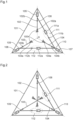
- a mobile rigid part 101 represented by an equilateral triangle, is guided in rotation relative to a support 100 around an axis of rotation. virtual A by a pivot comprising three connecting rods 102, 103, 104.
- the three connecting rods 102, 103, 104 extend along the bisectors of the equilateral triangle which intersect on the axis A.
- Each connecting rod 102, 103, 104 is joined by one of its ends to the support 100 via a hinge-type articulation 102a, 103a, 104a and by its other end to a respective intermediate rigid part 108, 109, 110 via another hinge-type articulation 102b, 103b, 104b.
- the intermediate rigid parts 108, 109, 110 are movable relative to each other and are guided in translation relative to the movable rigid part 101 along the bisectors of the equilateral triangle respectively by slide-type articulations 105, 106, 107.
- the intermediate rigid parts 108 and 110 are further connected directly to each other by an articulation 111 comprising, in series, a slide 111a oriented parallel to the corresponding side of the triangle and a hinge 111b.
- the intermediate rigid parts 109 and 110 are connected directly to each other by an articulation 112 comprising, in series, a slide 112a oriented parallel to the corresponding side of the triangle and a hinge 112b.
- the connecting rods 102, 103, 104 and the slides 105, 106, 107 are arranged around the axis A according to a symmetry of order 3.
- the intermediate rigid parts 108, 109, 110 each have a combined movement of rotation and radial translation relative to the axis A, the assembly that they form contracting or expanding in the manner of the closing and opening of an iris diaphragm depending on the direction of rotation of the mobile rigid part 101 and the sign of the angle of rotation of the mobile rigid part 101 relative to its equilibrium position illustrated in FIG. figure 1 .
- This system is isostatic and has a single degree of freedom (rotation of the mobile rigid part 101 relative to the support 100 around the axis A).
- the presence of the three connecting rods 102, 103, 104 contributes to reducing the parasitic movements of the axis A in comparison with pivots with only two connecting rods.
- the rotation of the mobile rigid part 101 is carried out without over-constraints thanks to the slides 105, 106, 107.
- the articulations 111, 112 between the intermediate rigid parts 108, 109, 110 force the latter to move in the same way and thus eliminate, with respect to the mobile rigid part 101, the degrees of freedom provided by the slides 105, 106, 107.
- This system does not have any internal degrees of freedom which could harm the shock resistance or make the system more sensitive to gravity.
- the connecting rods 102, 103, 104 stop before reaching the axis A, which makes it possible to give the system a flat shape.
- the system can be produced on several levels, as illustrated in figure 2 , so that the connecting rods 102, 103, 104 extend beyond the axis A.
- the connecting rods 102, 103, 104 can then cross (on the axis A) at points located approximately 50% of their length to maximize the travel of the mobile rigid part 101.
- FIG 3 shows a variant which takes up the characteristics of that of the figure 1 but in which the intermediate rigid parts 108 and 109 are connected directly to each other by a joint 113 comprising, in series, a slide 113a oriented parallel to the corresponding side of the triangle and a hinge 113b.
- An additional hinge 113c may be provided to avoid overstresses.
- the joint 113 is not necessary for the kinematics, but it makes it possible to improve the symmetry of the system and, consequently, to make the system less sensitive to gravity, even in the rest position, the collapse of the structure becoming less dependent on the direction of gravity and the mass being better distributed.
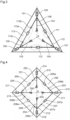
- FIG. 4 shows a variant with four connecting rods 202, 203, 204, 205, four intermediate rigid parts 210, 211, 212, 213 and four slides 214, 215, 216, 217.
- the movable rigid part, 201 is represented by a square. From the vertices of the square extend, in the direction of the axis A, the slides 214, 215, 216, 217 followed by the connecting rods 202, 203, 204, 205.
- a joint 206 comprising a slide 206a oriented parallel to the corresponding side of the square and a hinge 206b in series directly connects the intermediate rigid parts 210 and 211 to each other.
- a hinge 207 comprising a slide 207a oriented parallel to the corresponding side of the square and a hinge 207b in series directly connects the intermediate rigid parts 211 and 212 to each other.
- the connecting rods 202, 203, 204, 205 and the slides 214, 215, 216, 217 are arranged around the axis A according to a symmetry of order 4.
- an articulation 208 comprising, in series, a slide 208a, a hinge 208b and, preferably, an additional hinge 208c to avoid overstressing can directly connect the intermediate rigid parts 212 and 213 to each other, and a similar articulation 209 can directly connect the rigid parts 214 and 217 to each other.
- FIG. 5 To the figure 5 is shown a variant with three connecting rods 102, 103, 104, three intermediate rigid parts 108, 109, 110 and three slides 105, 106, 107 in which the articulations, designated by 115 and 116, which directly connect the intermediate rigid part 110 to the intermediate rigid parts 108 and 109 each comprise two hinges 115a, 115b, 116a, 116b in series rather than a slide and a hinge.
- the intermediate rigid part 108 can also be connected directly to the intermediate rigid part 109 by an articulation 117.
- this articulation 117 can comprise an additional hinge 117c to avoid overstresses.
- the architecture of the figure 5 has the advantage of being particularly simple to implement with elastic elements.
- Figures 1 to 5 are preferred to the extent that they have, at least in large part, a central symmetry around the axis A, which in particular reduces the dependence on gravity, and where their connecting rods 102 to 104 and 202 to 205 are oriented radially, giving the system a symmetrical behavior that is simpler to manage and maximizing the stroke for which the parasitic displacement of the axis A is minimal.
- Many other high-performance configurations are possible, with a lack of symmetry and/or connecting rods inclined relative to the radial direction.
- the figure 6 shows an asymmetrical system in which, in addition, the connecting rods 102, 103, 104 are non-radial.
- the virtual axis of rotation A corresponds to the center of the circle passing through the hinges 102a, 103a, 104a of the connecting rods 102, 103, 104.
- the connecting rods 102, 103, 104 are of equal length.
- the slides 105, 106, 107 are oriented radially with respect to the axis A.
- the connecting rods 102, 103, 104 are oriented such that their axes form the same angle with the axes of the slides 105, 106, 107 which are respectively connected to them.
- the slide 111a (respectively 112a) of the articulation 111 which connects the intermediate rigid parts 108, 110 (respectively 108, 109) extends along an axis which is perpendicular to the bisector of the axes of the slides 105, 107 (respectively 106, 107). It results from this coupling between the three intermediate rigid parts 108, 109, 110 that the movements of the three hinges 102b, 103b, 104b are necessarily concentric with respect to the axis A.
- This system like that of the previous figures, has a single degree of freedom (rotation of the mobile rigid part 101 with respect to the support 100 around the axis A) and is devoid of internal degrees of freedom. It is also devoid of hyperstaticism.
- FIG. 7 Another example of an asymmetric system is shown in figure 7 , where the connecting rods 102, 103, 104 are radial but where the axes of the slides 105, 106, 107 do not cross on the axis A.
- asymmetric systems may be designed with more than three links 202, 203, 204, 205 / intermediate rigid parts 210, 211, 212, 213, as shown in figure 8 .
- each slide 105, 106, 107 of the figure 5 is replaced by an arrangement of hinges 120, 121, 122.
- connecting rods 102, 103, 104 and the slides 105, 106, 107 i.e. to place the connecting rods 102, 103, 104 between the intermediate rigid parts 108, 109, 110 and the movable rigid part 101 and to place the slides 105, 106, 107 between the support 100 and the intermediate rigid parts 108, 109, 110, as illustrated in FIG. figure 10 .
- the slide-type joints 105 to 107 and 214 to 217 may be produced, for example, in the form of two parallel elastic blades or two parallel rigid segments articulated at their ends by elastic collars (two articulated segments such as that illustrated in FIG. figure 11(b) ).
- each flexible joint produces, compared to the ideal joints 102a, 102b, 103a, 103b, 104a, 104b, 105, 106, 107, a torque or an elastic restoring force when it is stressed.
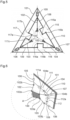
- FIG 12 shows an example of a concrete realization of a flexible pivot component 350 based on the principle of Figures 1 to 10 and more particularly of the figure 5 .
- Component 350 here is a watch oscillator intended to fulfill the function of a sprung balance, but it could be an anchor, a rocker, a lever or other.
- the component 350 has an external mobile rigid part 301, a central support 300 and a flexible pivot 351.
- the external mobile rigid part 301 of annular shape in the example shown, constitutes the inertial part of the oscillator.
- the central support 300 is intended to be fixed on a fixed or mobile frame, typically on the frame of a watch movement.
- the flexible pivot 351 suspends the external mobile rigid part 301 from the central support 300, guides it in rotation relative to the central support 300 around a virtual axis of rotation A and exerts an elastic restoring torque on it as soon as it deviates from an equilibrium position.
- the flexible pivot 351 comprises at least three elastic links 352, 353, 354 connecting, in parallel, the central support 300 and the external movable rigid part 301.
- Each elastic link 352, 353, 354 comprises, in series, an elastic blade 302, 303, 304, an intermediate rigid part 308, 309, 310 and a pair of parallel elastic blades 305, 306, 307.
- each elastic link 352, 353, 354 the elastic blade 302, 303, 304 extends radially with respect to the axis A, between the central support 300 and the intermediate rigid part 308, 309, 310, and the two parallel elastic blades 305, 306, 307 extend tangentially relative to the axis A, therefore perpendicular to the elastic blade 302, 303, 304, and connect the intermediate rigid part 308, 309, 310 to the external movable rigid part 301.
- the flexible pivot 351 further comprises elastic blades 315, 316, 317, oriented radially relative to the axis A, which directly connect the intermediate rigid parts 308, 309, 310 to each other.
- the elastic links 352, 353, 354 and the elastic blades 315, 316, 317 guide the intermediate rigid parts 308, 309, 310 both in rotation and in radial translation relative to the axis A when the external movable rigid part 301 is pivoted relative to the central support 300 about the axis A.
- the flexible pivot 351 preferably has a symmetry of order N relative to the axis A, where N is the number of elastic links 352, 353, 354.
- the elastic blades 302, 303, 304, the pairs of parallel blades 305, 306, 307 and the elastic blades 315, 316, 317 correspond respectively to the connecting rods 102, 103, 104, to the slides 105, 106, 107 and to the hinge joints 115, 116, 117 of the figure 5 .
- the additional degree of freedom provided by the 117c hinge on the figure 5 can be omitted, as component 350 is manufactured monolithically.
- Each of the elastic blades 302 to 307 and 315 to 317 can be replaced by an elastic element of the type shown in any one of the Figures 11(b) to 11(f) .
- the elastic blades 302, 303, 304, 315, 316, 317 could be inclined relative to the radial direction, for example, for the blades 302, 303, 304, to produce an isochronism defect compensating for another defect in the clockwork mechanism to which the component 350 belongs or to protect said blades from buckling.
- the parallel elastic blades 305, 306, 307 could be inclined relative to the tangential direction.
- the elastic blades 302, 303, 304 and the parallel elastic blades 305, 306, 307 could be interchanged according to the model proposed in the figure 10 .
- the component 350 has the dual advantage of having a flat shape and of offering the external mobile rigid part 301 a clean rotation, with little or no parasitic movements of the virtual axis of rotation A.
- the absence of parasitic movements of the virtual axis of rotation A further minimizes the influence of gravity on the frequency of the oscillator and thus improves the chronometry.
- the fact that the outer movable part 301 is rigid, rather than formed of rigid portions coupled by elastic elements facilitates the management of its shock resistance, its thermal expansion and the compensation to be provided (for example by depositing a coating on the flexible pivot 351) between the thermal drift of the stiffness of the flexible pivot 351 and that of the inertia of the outer movable part 301.
- the shock resistance is also improved by the parallel elastic translation guide blades 305, 306, 307 which protect the elastic rotation guide blades 302, 303, 304 from tensile or compressive forces by absorbing radial shocks.
- the parallel elastic blades 305, 306, 307 also reduce the sensitivity of the buckling structure when one of the elastic blades 302, 303, 304 is stressed in compression.
- the isochronism defect (variation of the frequency as a function of the oscillation amplitude) can be adjusted by modifying the non-linearity of the restoring torque of the flexible pivot 351 or the variation in inertia of the oscillator.
- To modify the non-linearity of the restoring torque it is possible to act on the stiffness of the flexible elements whose deformation is of second order relative to the rotation of the external mobile rigid part 301, namely the pairs of parallel blades 305, 306, 307 and the elastic blades 315, 316, 317.
- To modify the variation in inertia of the oscillator it is possible to act on the mass and the position of the center of mass of the intermediate rigid parts 308, 309, 310.
- the component 350 may be made of silicon, silicon dioxide coated silicon, glass, sapphire, quartz, metallic glass, metal or alloy, for example. Depending on the material chosen, the component is produced monolithically by etching (in particular deep reactive ion etching known as DRIE), LIGA, milling, electroerosion, casting or other.
- etching in particular deep reactive ion etching known as DRIE
- LIGA deep reactive ion etching
- milling electroerosion, casting or other.
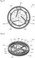
- FIGS. 13 to 15 show another example of a concrete embodiment of a flexible pivot component 450 not covered by the attached set of claims, based on the principle of Figures 1 to 10 and more particularly of the figure 2 .
- Component 450 here is a watch oscillator intended to fulfill the function of a sprung balance, but it could be an anchor, a rocker, a lever or other.
- This component 450 comprises an external movable rigid part 401, an internal support 400 and a flexible pivot 451 fulfilling the same functions, respectively, as the external movable rigid part 301, the central support 300 and the flexible pivot 351 of the component 350 illustrated in the figure. figure 12 .
- This component 450 is made up of at least three stages 460, 461, 462 each of which can be produced monolithically in one of the materials indicated above and by one of the techniques indicated above.
- the stages 460, 461, 462 are assembled together by welding, in particular thermocompression bonding, eutectic bonding or polymer bonding, by brazing, by gluing or otherwise.
- the external mobile rigid part 401, the internal support 400 and the flexible pivot 451 are each distributed over the different stages 460, 461, 462.
- the lines 463 at the figure 15 show where the rigid parts of component 450 are connected to each other.
- the flexible pivot 451 comprises at least three elastic links 452, 453, 454 connecting, in parallel, the inner support 400 and the outer movable rigid part 401 and each comprising, in series, an elastic blade 402, 403, 404, an intermediate rigid part 408, 409, 410 and a pair of parallel elastic blades 405, 406, 407.
- the flexible pivot 451 further comprises three elastic blades 415, 416, 417 directly connecting the intermediate rigid parts 408, 409, 410 to each other.
- These elastic links 452, 453, 454 and these elastic blades 415, 416, 417 minimize the parasitic movements of the virtual axis of rotation A.
- the flexible pivot 451 preferably has a symmetry of order N with respect to the virtual axis of rotation A in orthogonal projection in a plane perpendicular to the axis A, where N is the number of stages/elastic connections, this in order to give uniform radial rigidity to the component and thus to standardize the sagging of the component in the different vertical positions, therefore the differences in step in these positions.
- the construction of the Figures 13 to 15 however allows the elastic blades 402, 403, 404, each located on a respective stage 460, 461, 462, to cross, and advantageously to cross at a point located halfway along their length in order to optimize the travel of the external mobile rigid part 401 relative to the internal support 400.
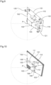
- THE figures 16 And 17 show a 550 clock oscillator comprising a 650 flexible pivot component similar to the 350 component of the figure 12 but in which the outer part, designated by 600, is fixed and constitutes the support and the central part, designated by 601, constitutes the rigid part guided in rotation by the flexible pivot 651 around the virtual axis of rotation A.
- the central part 601 is a hub mounted on a shaft 551 on which a balance 552 is also mounted.
- the shaft 551 and balance 552 assembly is held and guided only by the flexible pivot component 650 and its hub 601.
- the ends of the shaft 551 are therefore not intended to rub against bearings. They can nevertheless cooperate with fixed stops during impacts to protect the flexible pivot 651.
- the balance wheel 552 constitutes the inertial part of the oscillator 550 and the flexible pivot 651 its elastic part. Unlike a conventional flexible pivot oscillator and like a balance-spring oscillator, the oscillator 550 therefore has inertial and elastic parts which are separated. Such a separation allows the balance wheel 552 to be made of a material different from the - generally fragile - material of the flexible pivot 651, in particular in a dense material such as beryllium copper, gold or platinum. The balance wheel 552 can thus have a small diameter for a given moment of inertia. In this way, friction with the air will be reduced and the quality factor will be increased.
- the separation of the inertial part and the flexible pivot further facilitates the adjustment of the frequency of the oscillator 550.
- the moment of inertia and the unbalance of the balance 552 can indeed be measured and corrected easily while the torque of the flexible pivot 651 can be measured without prior assembly with the balance 552 and modified independently of the balance 552.
- Another advantage of the 550 component is that the attachment of the 600 bracket is made easier and more precise by the fact that the 600 bracket is an external part. away from the center. Yet another advantage is the possibility, as already mentioned, of protecting the flexible pivot 651 against permanent deformations or ruptures of its elastic elements due to external shocks or disturbances by using central stops cooperating with the shaft 551. Such central stops reduce the friction torque compared to stops cooperating with an external movable rigid part and thus reduce the risk of strong disturbances or even unexpected stops of the operation of the oscillator.
- the balance wheel 552 may be of the same type as that of traditional sprung balance oscillators and may be fixed to the shaft 551 in a conventional manner by riveting.
- the hub 601 may be fixed to the shaft 551 by gluing, welding, brazing, driving in or clamping by means of elastic arms, for example.
- a hub that is deformed when mounted on the shaft 551 is considered rigid in the present invention, in that it does not deform or hardly deforms during regular operation of the oscillator.
- the center of mass of the inertial part of the oscillator 550 is in the median plane of the flexible pivot to avoid creating an unbalance in the axial direction.
Landscapes
- Engineering & Computer Science (AREA)
- General Engineering & Computer Science (AREA)
- Mechanical Engineering (AREA)
- Physics & Mathematics (AREA)
- General Physics & Mathematics (AREA)
- Pivots And Pivotal Connections (AREA)
Claims (14)
- Komponente mit flexiblem Zapfen, die eine Stütze (300; 600) und einen beweglichen starren Teil (301; 601) umfasst, der an der Spitze (300; 600) durch einen flexiblen Zapfen (351; 651) aufgehängt ist, der dazu gestaltet ist, den beweglichen starren Teil (301; 601) in Bezug auf die Stütze (300; 600) um eine virtuelle Drehachse (A) drehbar zu führen, wobei die Komponente mit flexiblem Zapfen eben und monolithisch ist, wobei der flexible Zapfen (351; 651) mindestens drei elastische Verbindungen (352, 353, 354) umfasst, welche die Stütze (300; 600) und den beweglichen starren Teil (301; 601) parallel verbinden, wobei die Komponente mit flexiblem Zapfen dadurch gekennzeichnet ist, dass jede elastische Verbindung (352, 353, 354) in Reihe ein erstes elastisches Organ (302, 303, 304), einen starren Zwischenteil (308, 309, 310) und ein zweites elastisches Organ (305, 306, 307) umfasst, und dadurch, dass der flexible Zapfen (351; 651) ferner dritte elastische Organe (315, 316, 317) umfasst, die jeweils einen starren Zwischenteil (308, 309, 310) direkt mit einem anderen verbinden.
- Komponente mit flexiblem Zapfen nach Anspruch 1, dadurch gekennzeichnet, dass das erste elastische Organ (302, 303, 304) von jeder elastischen Verbindung (352, 353, 354) aus einer elastischen Klinge oder aus einem starren Segment besteht, das an seinen Enden durch elastische Gelenke drehbar gelenkig gelagert ist.
- Komponente mit flexiblem Zapfen nach Anspruch 1 oder 2, dadurch gekennzeichnet, dass das erste elastische Organ (302, 303, 304) von jeder elastischen Verbindung (352, 353, 354) sich im Wesentlichen radial in Bezug auf die virtuelle Drehachse (A) erstreckt.
- Komponente mit flexiblem Zapfen nach einem der Ansprüche 1 bis 3, dadurch gekennzeichnet, dass das zweite elastische Organ (305, 306, 307) von jeder elastischen Verbindung (352, 353, 354) zwei im Wesentlichen parallele elastische Elemente umfasst.
- Komponente mit flexiblem Zapfen nach einem der Ansprüche 1 bis 4, dadurch gekennzeichnet, dass das zweite elastische Organ (305, 306, 307) von jeder elastischen Verbindung (352, 353, 354) sich im Wesentlichen tangential in Bezug auf die virtuelle Drehachse (A) erstreckt.
- Komponente mit flexiblem Zapfen nach einem der Ansprüche 1 bis 5, dadurch gekennzeichnet, dass das erste und das zweite elastische Organ (302, 303, 304, 305, 306, 307) von jeder elastischen Verbindung (352, 353, 354) sich im Wesentlichen senkrecht zueinander erstrecken.
- Komponente mit flexiblem Zapfen nach einem der Ansprüche 1 bis 6, dadurch gekennzeichnet, dass jedes der dritten elastischen Organe (315, 316, 317) aus einer elastischen Klinge oder aus einem starren Segment besteht, das an seinen Enden durch elastische Gelenke drehbar gelenkig gelagert ist.
- Komponente mit flexiblem Zapfen nach einem der Ansprüche 1 bis 7, dadurch gekennzeichnet, dass die dritten elastischen Organe (315, 316, 317) sich im Wesentlichen radial in Bezug auf die virtuelle Drehachse (A) erstrecken.
- Komponente mit flexiblem Zapfen nach einem der Ansprüche 1 bis 8, dadurch gekennzeichnet, dass die elastischen Verbindungen (352, 353, 354) um die virtuelle Drehachse (A) herum im Wesentlichen gemäß einer Punktsymmetrie der Ordnung N in der Orthogonalprojektion in einer Ebene senkrecht zur virtuellen Drehachse (A) eingerichtet sind, wo N die Anzahl der elastischen Verbindungen (352, 353, 354; 452, 453, 454) ist.
- Komponente mit flexiblem Zapfen nach einem der Ansprüche 1 bis 9, dadurch gekennzeichnet, dass der flexible Zapfen (351; 651) im Wesentlichen eine Punktsymmetrie der Ordnung N in Bezug auf die virtuelle Drehachse (A) in der Orthogonalprojektion in einer Ebene senkrecht zur virtuellen Drehachse (A) aufweist, wo N die Anzahl der elastischen Verbindungen (352, 353, 354) ist.
- Komponente mit flexiblem Zapfen nach einem der Ansprüche 1 bis 10, dadurch gekennzeichnet, dass die Anzahl der elastischen Verbindungen (352, 353, 354) drei beträgt.
- Oszillator einer Uhr, der dazu bestimmt ist, die Funktion einer Unruh-Spiralfeder zu erfüllen und mindestens eine Komponente mit flexiblem Zapfen (350; 650) nach einem der Ansprüche 1 bis 11 umfasst.
- Oszillator einer Uhr nach Anspruch 12, dadurch gekennzeichnet, dass er mindestens eine Unruh (552) umfasst, die fest mit einer Welle (551) verbunden ist, die fest mit einer Nabe verbunden ist, die den beweglichen starren Teil (601) der oder jeder Komponente mit flexiblem Zapfen (650) bildet.
- Uhr, zum Beispiel Armbanduhr, Taschenuhr, Anhängeuhr oder Pendulette, die eine Komponente mit flexiblem Zapfen nach einem der Ansprüche 1 bis 11 oder einen Oszillator einer Uhr nach Anspruch 12 oder 13 umfasst.
Priority Applications (1)
| Application Number | Priority Date | Filing Date | Title |
|---|---|---|---|
| EP21157794.5A EP4047424B1 (de) | 2021-02-18 | 2021-02-18 | Komponente mit flexiblem zapfen, insbesondere für uhrwerk |
Applications Claiming Priority (1)
| Application Number | Priority Date | Filing Date | Title |
|---|---|---|---|
| EP21157794.5A EP4047424B1 (de) | 2021-02-18 | 2021-02-18 | Komponente mit flexiblem zapfen, insbesondere für uhrwerk |
Publications (2)
| Publication Number | Publication Date |
|---|---|
| EP4047424A1 EP4047424A1 (de) | 2022-08-24 |
| EP4047424B1 true EP4047424B1 (de) | 2024-12-04 |
Family
ID=74668651
Family Applications (1)
| Application Number | Title | Priority Date | Filing Date |
|---|---|---|---|
| EP21157794.5A Active EP4047424B1 (de) | 2021-02-18 | 2021-02-18 | Komponente mit flexiblem zapfen, insbesondere für uhrwerk |
Country Status (1)
| Country | Link |
|---|---|
| EP (1) | EP4047424B1 (de) |
Families Citing this family (2)
| Publication number | Priority date | Publication date | Assignee | Title |
|---|---|---|---|---|
| WO2024100597A1 (en) | 2022-11-09 | 2024-05-16 | Ecole Polytechnique Federale De Lausanne (Epfl) | Pivot, process for manufacturing such a pivot, oscillator comprising such a pivot, watch movement and timepiece comprising such an oscillator |
| EP4707946A1 (de) | 2024-09-09 | 2026-03-11 | Ecole Polytechnique Federale De Lausanne (Epfl) | Biegemechanismus mit reduzierter steifigkeit |
Family Cites Families (2)
| Publication number | Priority date | Publication date | Assignee | Title |
|---|---|---|---|---|
| FR3059792B1 (fr) | 2016-12-01 | 2019-05-24 | Lvmh Swiss Manufactures Sa | Dispositif pour piece d'horlogerie, mouvement horloger et piece d'horlogerie comprenant un tel dispositif |
| EP3476748B1 (de) * | 2017-10-24 | 2020-07-15 | CSEM Centre Suisse d'Electronique et de Microtechnique SA - Recherche et Développement | Schwenkmechanismus mit flexiblen elementen |
-
2021
- 2021-02-18 EP EP21157794.5A patent/EP4047424B1/de active Active
Also Published As
| Publication number | Publication date |
|---|---|
| EP4047424A1 (de) | 2022-08-24 |
Similar Documents
| Publication | Publication Date | Title |
|---|---|---|
| EP3054358B1 (de) | Oszillatormechanismus für uhr | |
| EP3548973B1 (de) | Vorrichtung für uhren, uhrmechanismus und uhr mit einer solchen vorrichtung. | |
| EP2998800B1 (de) | Uhrkomponente mit flexiblem zapfenlager | |
| EP3561607B1 (de) | Stossdämpfungsschutz eines resonatormechanismus mit flexibler drehführung | |
| CH709291A2 (fr) | Oscillateur de pièce d'horlogerie. | |
| WO2016124436A1 (fr) | Resonateur isochrone d'horlogerie | |
| EP4179391B1 (de) | Oszillator einer uhr mit flexiblem zapfen | |
| EP4047424B1 (de) | Komponente mit flexiblem zapfen, insbesondere für uhrwerk | |
| EP3792700B1 (de) | Oszillator einer uhr mit flexiblem zapfen | |
| EP3206091B1 (de) | Isochroner resonator für eine uhr | |
| CH715526A2 (fr) | Protection antichoc d'un mécanisme résonateur à guidage flexible rotatif. | |
| EP3561606B1 (de) | Stossdämpfungsschutz eines resonators mit rcc-schwenkfedern | |
| EP3555708B1 (de) | Uhrkomponente mit flexiblem zapfen | |
| EP3839651B1 (de) | Mechanischer oszillator einer uhr mit flexibler führung | |
| CH717996A2 (fr) | Guidage flexible avec table de translation pour mécanisme résonateur rotatif, notamment d'un mouvement d'horlogerie. | |
| EP3037893B1 (de) | Mikromechanische Komponente oder Uhr mit flexiblem Führungsdraht | |
| EP4191346B1 (de) | Stossdämpfungsschutz eines resonatormechanismus mit flexibler drehführung | |
| EP3971655A1 (de) | Stossdämpfungsschutz mit anschlag eines resonatormechanismus mit flexibler drehführung | |
| CH716725A2 (fr) | Dispositif de guidage en pivotement pour une masse pivotante et mécanisme résonateur d'horlogerie. | |
| EP3997525B1 (de) | Einstellverfahren eines uhrwerk-oszillators mit flexiblem zapfen | |
| EP3812842B1 (de) | Schwenkbare führungsvorrichtung für eine schwenkbare masse, und resonatormechanismus einer uhr | |
| EP3707564B1 (de) | Zusammenstellung einer uhrenkomponente und einer vorrichtung zur steuerung in längsrichtung einer beweglichen komponente | |
| EP3572885B1 (de) | Mechanischer oszillator eines isochronen uhrwerks in jeder position | |
| CH717880A2 (fr) | Mécanisme résonateur à guidage flexible rotatif avec protection antichoc à butée. | |
| CH719206A2 (fr) | Mécanisme résonateur d'horlogerie à guidage flexible rotatif. |
Legal Events
| Date | Code | Title | Description |
|---|---|---|---|
| PUAI | Public reference made under article 153(3) epc to a published international application that has entered the european phase |
Free format text: ORIGINAL CODE: 0009012 |
|
| STAA | Information on the status of an ep patent application or granted ep patent |
Free format text: STATUS: THE APPLICATION HAS BEEN PUBLISHED |
|
| AK | Designated contracting states |
Kind code of ref document: A1 Designated state(s): AL AT BE BG CH CY CZ DE DK EE ES FI FR GB GR HR HU IE IS IT LI LT LU LV MC MK MT NL NO PL PT RO RS SE SI SK SM TR |
|
| STAA | Information on the status of an ep patent application or granted ep patent |
Free format text: STATUS: REQUEST FOR EXAMINATION WAS MADE |
|
| 17P | Request for examination filed |
Effective date: 20230120 |
|
| RBV | Designated contracting states (corrected) |
Designated state(s): AL AT BE BG CH CY CZ DE DK EE ES FI FR GB GR HR HU IE IS IT LI LT LU LV MC MK MT NL NO PL PT RO RS SE SI SK SM TR |
|
| P01 | Opt-out of the competence of the unified patent court (upc) registered |
Effective date: 20230521 |
|
| REG | Reference to a national code |
Ref country code: DE Ref legal event code: R079 Free format text: PREVIOUS MAIN CLASS: G04B0017040000 Ipc: F16C0011040000 Ref country code: DE Ref legal event code: R079 Ref document number: 602021022685 Country of ref document: DE Free format text: PREVIOUS MAIN CLASS: G04B0017040000 Ipc: F16C0011040000 |
|
| GRAP | Despatch of communication of intention to grant a patent |
Free format text: ORIGINAL CODE: EPIDOSNIGR1 |
|
| STAA | Information on the status of an ep patent application or granted ep patent |
Free format text: STATUS: GRANT OF PATENT IS INTENDED |
|
| RIC1 | Information provided on ipc code assigned before grant |
Ipc: G04B 17/04 20060101ALI20240711BHEP Ipc: F16C 11/12 20060101ALI20240711BHEP Ipc: G04B 31/00 20060101ALI20240711BHEP Ipc: F16C 11/04 20060101AFI20240711BHEP |
|
| INTG | Intention to grant announced |
Effective date: 20240726 |
|
| GRAS | Grant fee paid |
Free format text: ORIGINAL CODE: EPIDOSNIGR3 |
|
| GRAA | (expected) grant |
Free format text: ORIGINAL CODE: 0009210 |
|
| STAA | Information on the status of an ep patent application or granted ep patent |
Free format text: STATUS: THE PATENT HAS BEEN GRANTED |
|
| AK | Designated contracting states |
Kind code of ref document: B1 Designated state(s): AL AT BE BG CH CY CZ DE DK EE ES FI FR GB GR HR HU IE IS IT LI LT LU LV MC MK MT NL NO PL PT RO RS SE SI SK SM TR |
|
| REG | Reference to a national code |
Ref country code: CH Ref legal event code: EP |
|
| REG | Reference to a national code |
Ref country code: DE Ref legal event code: R096 Ref document number: 602021022685 Country of ref document: DE |
|
| REG | Reference to a national code |
Ref country code: IE Ref legal event code: FG4D Free format text: LANGUAGE OF EP DOCUMENT: FRENCH |
|
| REG | Reference to a national code |
Ref country code: LT Ref legal event code: MG9D |
|
| REG | Reference to a national code |
Ref country code: NL Ref legal event code: MP Effective date: 20241204 |
|
| PG25 | Lapsed in a contracting state [announced via postgrant information from national office to epo] |
Ref country code: HR Free format text: LAPSE BECAUSE OF FAILURE TO SUBMIT A TRANSLATION OF THE DESCRIPTION OR TO PAY THE FEE WITHIN THE PRESCRIBED TIME-LIMIT Effective date: 20241204 |
|
| PG25 | Lapsed in a contracting state [announced via postgrant information from national office to epo] |
Ref country code: FI Free format text: LAPSE BECAUSE OF FAILURE TO SUBMIT A TRANSLATION OF THE DESCRIPTION OR TO PAY THE FEE WITHIN THE PRESCRIBED TIME-LIMIT Effective date: 20241204 |
|
| PG25 | Lapsed in a contracting state [announced via postgrant information from national office to epo] |
Ref country code: BG Free format text: LAPSE BECAUSE OF FAILURE TO SUBMIT A TRANSLATION OF THE DESCRIPTION OR TO PAY THE FEE WITHIN THE PRESCRIBED TIME-LIMIT Effective date: 20241204 |
|
| PG25 | Lapsed in a contracting state [announced via postgrant information from national office to epo] |
Ref country code: ES Free format text: LAPSE BECAUSE OF FAILURE TO SUBMIT A TRANSLATION OF THE DESCRIPTION OR TO PAY THE FEE WITHIN THE PRESCRIBED TIME-LIMIT Effective date: 20241204 |
|
| PG25 | Lapsed in a contracting state [announced via postgrant information from national office to epo] |
Ref country code: NO Free format text: LAPSE BECAUSE OF FAILURE TO SUBMIT A TRANSLATION OF THE DESCRIPTION OR TO PAY THE FEE WITHIN THE PRESCRIBED TIME-LIMIT Effective date: 20250304 |
|
| PG25 | Lapsed in a contracting state [announced via postgrant information from national office to epo] |
Ref country code: LV Free format text: LAPSE BECAUSE OF FAILURE TO SUBMIT A TRANSLATION OF THE DESCRIPTION OR TO PAY THE FEE WITHIN THE PRESCRIBED TIME-LIMIT Effective date: 20241204 Ref country code: GR Free format text: LAPSE BECAUSE OF FAILURE TO SUBMIT A TRANSLATION OF THE DESCRIPTION OR TO PAY THE FEE WITHIN THE PRESCRIBED TIME-LIMIT Effective date: 20250305 |
|
| PGFP | Annual fee paid to national office [announced via postgrant information from national office to epo] |
Ref country code: CH Payment date: 20250301 Year of fee payment: 5 |
|
| PG25 | Lapsed in a contracting state [announced via postgrant information from national office to epo] |
Ref country code: RS Free format text: LAPSE BECAUSE OF FAILURE TO SUBMIT A TRANSLATION OF THE DESCRIPTION OR TO PAY THE FEE WITHIN THE PRESCRIBED TIME-LIMIT Effective date: 20250304 |
|
| PG25 | Lapsed in a contracting state [announced via postgrant information from national office to epo] |
Ref country code: NL Free format text: LAPSE BECAUSE OF FAILURE TO SUBMIT A TRANSLATION OF THE DESCRIPTION OR TO PAY THE FEE WITHIN THE PRESCRIBED TIME-LIMIT Effective date: 20241204 |
|
| REG | Reference to a national code |
Ref country code: AT Ref legal event code: MK05 Ref document number: 1748452 Country of ref document: AT Kind code of ref document: T Effective date: 20241204 |
|
| PG25 | Lapsed in a contracting state [announced via postgrant information from national office to epo] |
Ref country code: SM Free format text: LAPSE BECAUSE OF FAILURE TO SUBMIT A TRANSLATION OF THE DESCRIPTION OR TO PAY THE FEE WITHIN THE PRESCRIBED TIME-LIMIT Effective date: 20241204 |
|
| PG25 | Lapsed in a contracting state [announced via postgrant information from national office to epo] |
Ref country code: PL Free format text: LAPSE BECAUSE OF FAILURE TO SUBMIT A TRANSLATION OF THE DESCRIPTION OR TO PAY THE FEE WITHIN THE PRESCRIBED TIME-LIMIT Effective date: 20241204 |
|
| PG25 | Lapsed in a contracting state [announced via postgrant information from national office to epo] |
Ref country code: IS Free format text: LAPSE BECAUSE OF FAILURE TO SUBMIT A TRANSLATION OF THE DESCRIPTION OR TO PAY THE FEE WITHIN THE PRESCRIBED TIME-LIMIT Effective date: 20250404 |
|
| PG25 | Lapsed in a contracting state [announced via postgrant information from national office to epo] |
Ref country code: PT Free format text: LAPSE BECAUSE OF FAILURE TO SUBMIT A TRANSLATION OF THE DESCRIPTION OR TO PAY THE FEE WITHIN THE PRESCRIBED TIME-LIMIT Effective date: 20250404 |
|
| PG25 | Lapsed in a contracting state [announced via postgrant information from national office to epo] |
Ref country code: EE Free format text: LAPSE BECAUSE OF FAILURE TO SUBMIT A TRANSLATION OF THE DESCRIPTION OR TO PAY THE FEE WITHIN THE PRESCRIBED TIME-LIMIT Effective date: 20241204 |
|
| PG25 | Lapsed in a contracting state [announced via postgrant information from national office to epo] |
Ref country code: AT Free format text: LAPSE BECAUSE OF FAILURE TO SUBMIT A TRANSLATION OF THE DESCRIPTION OR TO PAY THE FEE WITHIN THE PRESCRIBED TIME-LIMIT Effective date: 20241204 Ref country code: RO Free format text: LAPSE BECAUSE OF FAILURE TO SUBMIT A TRANSLATION OF THE DESCRIPTION OR TO PAY THE FEE WITHIN THE PRESCRIBED TIME-LIMIT Effective date: 20241204 |
|
| PG25 | Lapsed in a contracting state [announced via postgrant information from national office to epo] |
Ref country code: SK Free format text: LAPSE BECAUSE OF FAILURE TO SUBMIT A TRANSLATION OF THE DESCRIPTION OR TO PAY THE FEE WITHIN THE PRESCRIBED TIME-LIMIT Effective date: 20241204 |
|
| PG25 | Lapsed in a contracting state [announced via postgrant information from national office to epo] |
Ref country code: CZ Free format text: LAPSE BECAUSE OF FAILURE TO SUBMIT A TRANSLATION OF THE DESCRIPTION OR TO PAY THE FEE WITHIN THE PRESCRIBED TIME-LIMIT Effective date: 20241204 |
|
| PG25 | Lapsed in a contracting state [announced via postgrant information from national office to epo] |
Ref country code: IT Free format text: LAPSE BECAUSE OF FAILURE TO SUBMIT A TRANSLATION OF THE DESCRIPTION OR TO PAY THE FEE WITHIN THE PRESCRIBED TIME-LIMIT Effective date: 20241204 |
|
| REG | Reference to a national code |
Ref country code: DE Ref legal event code: R119 Ref document number: 602021022685 Country of ref document: DE |
|
| PG25 | Lapsed in a contracting state [announced via postgrant information from national office to epo] |
Ref country code: SE Free format text: LAPSE BECAUSE OF FAILURE TO SUBMIT A TRANSLATION OF THE DESCRIPTION OR TO PAY THE FEE WITHIN THE PRESCRIBED TIME-LIMIT Effective date: 20241204 |
|
| PG25 | Lapsed in a contracting state [announced via postgrant information from national office to epo] |
Ref country code: MC Free format text: LAPSE BECAUSE OF FAILURE TO SUBMIT A TRANSLATION OF THE DESCRIPTION OR TO PAY THE FEE WITHIN THE PRESCRIBED TIME-LIMIT Effective date: 20241204 |
|
| PG25 | Lapsed in a contracting state [announced via postgrant information from national office to epo] |
Ref country code: DK Free format text: LAPSE BECAUSE OF FAILURE TO SUBMIT A TRANSLATION OF THE DESCRIPTION OR TO PAY THE FEE WITHIN THE PRESCRIBED TIME-LIMIT Effective date: 20241204 |
|
| PLBE | No opposition filed within time limit |
Free format text: ORIGINAL CODE: 0009261 |
|
| STAA | Information on the status of an ep patent application or granted ep patent |
Free format text: STATUS: NO OPPOSITION FILED WITHIN TIME LIMIT |
|
| PG25 | Lapsed in a contracting state [announced via postgrant information from national office to epo] |
Ref country code: LU Free format text: LAPSE BECAUSE OF NON-PAYMENT OF DUE FEES Effective date: 20250218 |
|
| REG | Reference to a national code |
Ref country code: CH Ref legal event code: L10 Free format text: ST27 STATUS EVENT CODE: U-0-0-L10-L00 (AS PROVIDED BY THE NATIONAL OFFICE) Effective date: 20251015 |
|
| 26N | No opposition filed |
Effective date: 20250905 |
|
| GBPC | Gb: european patent ceased through non-payment of renewal fee |
Effective date: 20250304 |
|
| REG | Reference to a national code |
Ref country code: BE Ref legal event code: MM Effective date: 20250228 |
|
| PG25 | Lapsed in a contracting state [announced via postgrant information from national office to epo] |
Ref country code: DE Free format text: LAPSE BECAUSE OF NON-PAYMENT OF DUE FEES Effective date: 20250902 |
|
| PG25 | Lapsed in a contracting state [announced via postgrant information from national office to epo] |
Ref country code: GB Free format text: LAPSE BECAUSE OF NON-PAYMENT OF DUE FEES Effective date: 20250304 |
|
| PG25 | Lapsed in a contracting state [announced via postgrant information from national office to epo] |
Ref country code: FR Free format text: LAPSE BECAUSE OF NON-PAYMENT OF DUE FEES Effective date: 20250228 |
|
| PG25 | Lapsed in a contracting state [announced via postgrant information from national office to epo] |
Ref country code: BE Free format text: LAPSE BECAUSE OF NON-PAYMENT OF DUE FEES Effective date: 20250228 |
|
| PG25 | Lapsed in a contracting state [announced via postgrant information from national office to epo] |
Ref country code: IE Free format text: LAPSE BECAUSE OF NON-PAYMENT OF DUE FEES Effective date: 20250218 |
|
| REG | Reference to a national code |
Ref country code: CH Ref legal event code: U11 Free format text: ST27 STATUS EVENT CODE: U-0-0-U10-U11 (AS PROVIDED BY THE NATIONAL OFFICE) Effective date: 20260301 |