EP4137873A1 - Système d'affichage tête haute et procédé d'affichage d'image basé sur le système d'affichage tête haute - Google Patents
Système d'affichage tête haute et procédé d'affichage d'image basé sur le système d'affichage tête haute Download PDFInfo
- Publication number
- EP4137873A1 EP4137873A1 EP21804282.8A EP21804282A EP4137873A1 EP 4137873 A1 EP4137873 A1 EP 4137873A1 EP 21804282 A EP21804282 A EP 21804282A EP 4137873 A1 EP4137873 A1 EP 4137873A1
- Authority
- EP
- European Patent Office
- Prior art keywords
- windshield
- windshield surface
- light beam
- optical element
- human eye
- Prior art date
- Legal status (The legal status is an assumption and is not a legal conclusion. Google has not performed a legal analysis and makes no representation as to the accuracy of the status listed.)
- Pending
Links
- 238000000034 method Methods 0.000 title claims abstract description 31
- 230000003287 optical effect Effects 0.000 claims abstract description 102
- 239000011229 interlayer Substances 0.000 claims description 8
- XUIMIQQOPSSXEZ-UHFFFAOYSA-N Silicon Chemical compound [Si] XUIMIQQOPSSXEZ-UHFFFAOYSA-N 0.000 claims description 6
- 239000004973 liquid crystal related substance Substances 0.000 claims description 6
- 229910052710 silicon Inorganic materials 0.000 claims description 6
- 239000010703 silicon Substances 0.000 claims description 6
- 238000003384 imaging method Methods 0.000 claims description 5
- 230000000007 visual effect Effects 0.000 abstract description 7
- 238000010586 diagram Methods 0.000 description 22
- ORQBXQOJMQIAOY-UHFFFAOYSA-N nobelium Chemical compound [No] ORQBXQOJMQIAOY-UHFFFAOYSA-N 0.000 description 19
- 239000000446 fuel Substances 0.000 description 1
- 239000011521 glass Substances 0.000 description 1
- 239000005340 laminated glass Substances 0.000 description 1
- 238000012986 modification Methods 0.000 description 1
- 230000004048 modification Effects 0.000 description 1
- 229920000642 polymer Polymers 0.000 description 1
- 229920006254 polymer film Polymers 0.000 description 1
Images


Classifications
-
- B—PERFORMING OPERATIONS; TRANSPORTING
- B60—VEHICLES IN GENERAL
- B60K—ARRANGEMENT OR MOUNTING OF PROPULSION UNITS OR OF TRANSMISSIONS IN VEHICLES; ARRANGEMENT OR MOUNTING OF PLURAL DIVERSE PRIME-MOVERS IN VEHICLES; AUXILIARY DRIVES FOR VEHICLES; INSTRUMENTATION OR DASHBOARDS FOR VEHICLES; ARRANGEMENTS IN CONNECTION WITH COOLING, AIR INTAKE, GAS EXHAUST OR FUEL SUPPLY OF PROPULSION UNITS IN VEHICLES
- B60K35/00—Instruments specially adapted for vehicles; Arrangement of instruments in or on vehicles
-
- G—PHYSICS
- G02—OPTICS
- G02B—OPTICAL ELEMENTS, SYSTEMS OR APPARATUS
- G02B27/00—Optical systems or apparatus not provided for by any of the groups G02B1/00 - G02B26/00, G02B30/00
- G02B27/01—Head-up displays
- G02B27/0101—Head-up displays characterised by optical features
-
- B—PERFORMING OPERATIONS; TRANSPORTING
- B60—VEHICLES IN GENERAL
- B60K—ARRANGEMENT OR MOUNTING OF PROPULSION UNITS OR OF TRANSMISSIONS IN VEHICLES; ARRANGEMENT OR MOUNTING OF PLURAL DIVERSE PRIME-MOVERS IN VEHICLES; AUXILIARY DRIVES FOR VEHICLES; INSTRUMENTATION OR DASHBOARDS FOR VEHICLES; ARRANGEMENTS IN CONNECTION WITH COOLING, AIR INTAKE, GAS EXHAUST OR FUEL SUPPLY OF PROPULSION UNITS IN VEHICLES
- B60K35/00—Instruments specially adapted for vehicles; Arrangement of instruments in or on vehicles
- B60K35/20—Output arrangements, i.e. from vehicle to user, associated with vehicle functions or specially adapted therefor
- B60K35/21—Output arrangements, i.e. from vehicle to user, associated with vehicle functions or specially adapted therefor using visual output, e.g. blinking lights or matrix displays
- B60K35/23—Head-up displays [HUD]
-
- B—PERFORMING OPERATIONS; TRANSPORTING
- B60—VEHICLES IN GENERAL
- B60K—ARRANGEMENT OR MOUNTING OF PROPULSION UNITS OR OF TRANSMISSIONS IN VEHICLES; ARRANGEMENT OR MOUNTING OF PLURAL DIVERSE PRIME-MOVERS IN VEHICLES; AUXILIARY DRIVES FOR VEHICLES; INSTRUMENTATION OR DASHBOARDS FOR VEHICLES; ARRANGEMENTS IN CONNECTION WITH COOLING, AIR INTAKE, GAS EXHAUST OR FUEL SUPPLY OF PROPULSION UNITS IN VEHICLES
- B60K35/00—Instruments specially adapted for vehicles; Arrangement of instruments in or on vehicles
- B60K35/40—Instruments specially adapted for improving the visibility thereof to the user, e.g. fogging prevention or anti-reflection arrangements
- B60K35/405—Fogging prevention
-
- B—PERFORMING OPERATIONS; TRANSPORTING
- B60—VEHICLES IN GENERAL
- B60K—ARRANGEMENT OR MOUNTING OF PROPULSION UNITS OR OF TRANSMISSIONS IN VEHICLES; ARRANGEMENT OR MOUNTING OF PLURAL DIVERSE PRIME-MOVERS IN VEHICLES; AUXILIARY DRIVES FOR VEHICLES; INSTRUMENTATION OR DASHBOARDS FOR VEHICLES; ARRANGEMENTS IN CONNECTION WITH COOLING, AIR INTAKE, GAS EXHAUST OR FUEL SUPPLY OF PROPULSION UNITS IN VEHICLES
- B60K35/00—Instruments specially adapted for vehicles; Arrangement of instruments in or on vehicles
- B60K35/60—Instruments characterised by their location or relative disposition in or on vehicles
-
- B—PERFORMING OPERATIONS; TRANSPORTING
- B60—VEHICLES IN GENERAL
- B60K—ARRANGEMENT OR MOUNTING OF PROPULSION UNITS OR OF TRANSMISSIONS IN VEHICLES; ARRANGEMENT OR MOUNTING OF PLURAL DIVERSE PRIME-MOVERS IN VEHICLES; AUXILIARY DRIVES FOR VEHICLES; INSTRUMENTATION OR DASHBOARDS FOR VEHICLES; ARRANGEMENTS IN CONNECTION WITH COOLING, AIR INTAKE, GAS EXHAUST OR FUEL SUPPLY OF PROPULSION UNITS IN VEHICLES
- B60K35/00—Instruments specially adapted for vehicles; Arrangement of instruments in or on vehicles
- B60K35/65—Instruments specially adapted for specific vehicle types or users, e.g. for left- or right-hand drive
-
- G—PHYSICS
- G02—OPTICS
- G02B—OPTICAL ELEMENTS, SYSTEMS OR APPARATUS
- G02B27/00—Optical systems or apparatus not provided for by any of the groups G02B1/00 - G02B26/00, G02B30/00
- G02B27/01—Head-up displays
- G02B27/0149—Head-up displays characterised by mechanical features
-
- B—PERFORMING OPERATIONS; TRANSPORTING
- B60—VEHICLES IN GENERAL
- B60K—ARRANGEMENT OR MOUNTING OF PROPULSION UNITS OR OF TRANSMISSIONS IN VEHICLES; ARRANGEMENT OR MOUNTING OF PLURAL DIVERSE PRIME-MOVERS IN VEHICLES; AUXILIARY DRIVES FOR VEHICLES; INSTRUMENTATION OR DASHBOARDS FOR VEHICLES; ARRANGEMENTS IN CONNECTION WITH COOLING, AIR INTAKE, GAS EXHAUST OR FUEL SUPPLY OF PROPULSION UNITS IN VEHICLES
- B60K2360/00—Indexing scheme associated with groups B60K35/00 or B60K37/00 relating to details of instruments or dashboards
- B60K2360/20—Optical features of instruments
- B60K2360/23—Optical features of instruments using reflectors
-
- B—PERFORMING OPERATIONS; TRANSPORTING
- B60—VEHICLES IN GENERAL
- B60K—ARRANGEMENT OR MOUNTING OF PROPULSION UNITS OR OF TRANSMISSIONS IN VEHICLES; ARRANGEMENT OR MOUNTING OF PLURAL DIVERSE PRIME-MOVERS IN VEHICLES; AUXILIARY DRIVES FOR VEHICLES; INSTRUMENTATION OR DASHBOARDS FOR VEHICLES; ARRANGEMENTS IN CONNECTION WITH COOLING, AIR INTAKE, GAS EXHAUST OR FUEL SUPPLY OF PROPULSION UNITS IN VEHICLES
- B60K2360/00—Indexing scheme associated with groups B60K35/00 or B60K37/00 relating to details of instruments or dashboards
- B60K2360/20—Optical features of instruments
- B60K2360/25—Optical features of instruments using filters
-
- B—PERFORMING OPERATIONS; TRANSPORTING
- B60—VEHICLES IN GENERAL
- B60K—ARRANGEMENT OR MOUNTING OF PROPULSION UNITS OR OF TRANSMISSIONS IN VEHICLES; ARRANGEMENT OR MOUNTING OF PLURAL DIVERSE PRIME-MOVERS IN VEHICLES; AUXILIARY DRIVES FOR VEHICLES; INSTRUMENTATION OR DASHBOARDS FOR VEHICLES; ARRANGEMENTS IN CONNECTION WITH COOLING, AIR INTAKE, GAS EXHAUST OR FUEL SUPPLY OF PROPULSION UNITS IN VEHICLES
- B60K2360/00—Indexing scheme associated with groups B60K35/00 or B60K37/00 relating to details of instruments or dashboards
- B60K2360/20—Optical features of instruments
- B60K2360/31—Virtual images
-
- B—PERFORMING OPERATIONS; TRANSPORTING
- B60—VEHICLES IN GENERAL
- B60K—ARRANGEMENT OR MOUNTING OF PROPULSION UNITS OR OF TRANSMISSIONS IN VEHICLES; ARRANGEMENT OR MOUNTING OF PLURAL DIVERSE PRIME-MOVERS IN VEHICLES; AUXILIARY DRIVES FOR VEHICLES; INSTRUMENTATION OR DASHBOARDS FOR VEHICLES; ARRANGEMENTS IN CONNECTION WITH COOLING, AIR INTAKE, GAS EXHAUST OR FUEL SUPPLY OF PROPULSION UNITS IN VEHICLES
- B60K2360/00—Indexing scheme associated with groups B60K35/00 or B60K37/00 relating to details of instruments or dashboards
- B60K2360/20—Optical features of instruments
- B60K2360/33—Illumination features
- B60K2360/336—Light guides
-
- B—PERFORMING OPERATIONS; TRANSPORTING
- B60—VEHICLES IN GENERAL
- B60K—ARRANGEMENT OR MOUNTING OF PROPULSION UNITS OR OF TRANSMISSIONS IN VEHICLES; ARRANGEMENT OR MOUNTING OF PLURAL DIVERSE PRIME-MOVERS IN VEHICLES; AUXILIARY DRIVES FOR VEHICLES; INSTRUMENTATION OR DASHBOARDS FOR VEHICLES; ARRANGEMENTS IN CONNECTION WITH COOLING, AIR INTAKE, GAS EXHAUST OR FUEL SUPPLY OF PROPULSION UNITS IN VEHICLES
- B60K2360/00—Indexing scheme associated with groups B60K35/00 or B60K37/00 relating to details of instruments or dashboards
- B60K2360/77—Instrument locations other than the dashboard
- B60K2360/785—Instrument locations other than the dashboard on or in relation to the windshield or windows
-
- G—PHYSICS
- G02—OPTICS
- G02B—OPTICAL ELEMENTS, SYSTEMS OR APPARATUS
- G02B27/00—Optical systems or apparatus not provided for by any of the groups G02B1/00 - G02B26/00, G02B30/00
- G02B27/01—Head-up displays
- G02B27/0101—Head-up displays characterised by optical features
- G02B2027/0118—Head-up displays characterised by optical features comprising devices for improving the contrast of the display / brillance control visibility
- G02B2027/012—Head-up displays characterised by optical features comprising devices for improving the contrast of the display / brillance control visibility comprising devices for attenuating parasitic image effects
-
- G—PHYSICS
- G02—OPTICS
- G02B—OPTICAL ELEMENTS, SYSTEMS OR APPARATUS
- G02B27/00—Optical systems or apparatus not provided for by any of the groups G02B1/00 - G02B26/00, G02B30/00
- G02B27/01—Head-up displays
- G02B27/0101—Head-up displays characterised by optical features
- G02B2027/014—Head-up displays characterised by optical features comprising information/image processing systems
-
- G—PHYSICS
- G02—OPTICS
- G02B—OPTICAL ELEMENTS, SYSTEMS OR APPARATUS
- G02B27/00—Optical systems or apparatus not provided for by any of the groups G02B1/00 - G02B26/00, G02B30/00
- G02B27/01—Head-up displays
- G02B27/0149—Head-up displays characterised by mechanical features
- G02B2027/0154—Head-up displays characterised by mechanical features with movable elements
-
- G—PHYSICS
- G02—OPTICS
- G02B—OPTICAL ELEMENTS, SYSTEMS OR APPARATUS
- G02B27/00—Optical systems or apparatus not provided for by any of the groups G02B1/00 - G02B26/00, G02B30/00
- G02B27/01—Head-up displays
- G02B2027/0192—Supplementary details
- G02B2027/0196—Supplementary details having transparent supporting structure for display mounting, e.g. to a window or a windshield
Definitions
- This application relates to the field of vehicles, and in particular, to a head-up display system and an image display method based on the head-up display system.
- a head-up display (Head-up Display, HUD) is an important technology for improving driving safety of a vehicle. It can project instrument information such as a driving speed and a fuel quantity and navigation information into a human eye by using components such as an imaging source and a mirror, and then establish a virtual image outside a windshield, so that a driver can observe driving information without lowering the head, thereby avoiding distracting attention, to improve driving safety and driving experience.
- instrument information such as a driving speed and a fuel quantity and navigation information into a human eye by using components such as an imaging source and a mirror, and then establish a virtual image outside a windshield, so that a driver can observe driving information without lowering the head, thereby avoiding distracting attention, to improve driving safety and driving experience.
- an existing vehicle windshield is generally sandwich-shaped laminated glass, and two pieces of glass are bonded together by using a polymer film.
- the light When light projected by the HUD is incident on the windshield, the light may be reflected on two interfaces in contact with air inside and outside the windshield, and two virtual images are formed.
- the two virtual images may form a ghost image due to partial overlapping, which seriously affects HUD clarity.
- Embodiments of the present invention disclose a head-up display system and an image display method based on the head-up display system, which can effectively eliminate visual interference to a human eye caused by a ghost image of two virtual images.
- this application provides an HUD system.
- the HUD system includes a windshield, a picture generation unit (Picture Generation Unit, PGU), and an optical element, where the windshield includes a first windshield surface and a second windshield surface.
- the PGU projects a light beam corresponding to a picture generated by the PGU to the optical element.
- the optical element directs the light beam to the first windshield surface.
- the first windshield surface refracts the light beam to the second windshield surface, and reflects the light beam to a human eye for receiving.
- the first windshield surface further refracts a light beam reflected from the second windshield surface to the human eye for receiving. After reflection by the first windshield surface, the light beam forms a first virtual image with the picture.
- the light beam After reflection by the second windshield surface and refraction by the first windshield surface, the light beam forms a second virtual image with the picture.
- an included angle between the human eye and either of the first virtual image and the second virtual image is less than a preset angle.
- the included angle may be calculated by using a thickness of the windshield, a refractive index of the windshield, a coangle of an incident angle, on the first windshield surface, of the light beam directed by the optical element to the first windshield surface, and a distance between the first virtual image and the human eye.
- the foregoing preset angle generally refers to a resolution of the human eye (which may also be referred to as a distinguishable angle or an angular resolution of the human eye). Generally, a resolution of a normal human eye is 0.02°. It should be understood that a specific value of the foregoing preset angle is not limited in this application, provided that an included angle between the two virtual images and the human eye is small enough so that the human eye cannot distinguish between the two virtual images.
- points at a same position on the first virtual image and the second virtual image are selected, for example, a center point in the first virtual image and a center point in the second virtual image.
- a position of the human eye is considered as a point.
- a direction from the center point of the first virtual image to the human eye is denoted as a first direction
- a direction from the center point of the second virtual image to the human eye is denoted as a second direction.
- an included angle between the first direction and the second direction is the included angle between the two virtual images and the human eye.
- the picture generated by the PGU forms two virtual images in front of the windshield.
- the included angle between the two virtual images and the human eye is related to a plurality of parameters (for example, the thickness of the windshield, the refractive index of the windshield, the coangle of the incident angle, on the first windshield surface, of the light beam directed by the optical element to the first windshield surface, and the distance between the first virtual image and the human eye).
- the included angle between the two virtual images and the human eye may be less than the preset angle (for example, the resolution of the human eye) by adjusting the foregoing listed parameters. Then, the human eye cannot distinguish between the two virtual images, so that visual interference to the human eye caused by a ghost image of the two virtual images can be effectively eliminated.
- the HUD system further includes a first driving apparatus and/or a second driving apparatus.
- the first driving apparatus is configured to adjust a position of the PGU, so that the PGU is close to or away from the optical element.
- the second driving apparatus is configured to adjust a position of the optical element, so that the optical element is close to or away from the PGU.
- a distance between the PGU and the optical element can be dynamically adjusted, so that the distance between the first virtual image and the human eye can be dynamically adjusted, to ensure that the included angle between the two virtual images and the human eye is less than the preset angle, which improves practicality of the solution.
- the first driving apparatus is further configured to drive the PGU to rotate, to adjust a size of the coangle of the incident angle of the light beam on the first windshield surface.
- the second driving apparatus is further configured to drive the optical element to rotate, to adjust the size of the coangle of the incident angle of the light beam on the first windshield surface.
- the size of the coangle of the incident angle of the light beam on the first windshield surface can be dynamically adjusted by using the driving apparatus, to ensure that the included angle between the two virtual images and the human eye is less than the preset angle, which further improves practicality of the solution.
- the distance between the first virtual image and the human eye is equal to a sum of a first distance and a second distance.
- the first distance is a distance between the first virtual image and a target position on the first windshield surface
- the second distance is a distance between the target position on the first windshield surface and the human eye
- the first distance is determined by a focal length of the optical element and a distance between the PGU and the optical element.
- the distance between the first virtual image and the human eye can be changed by changing the first distance and/or the second distance.
- the first distance may be changed by adjusting the focal length of the optical element and the distance between the PGU and the optical element.
- the second distance may be changed by adjusting a distance between an observer and the windshield. Scalability of this solution is improved.
- the included angle is calculated by substituting the thickness of the windshield, the refractive index of the windshield, the coangle, and the distance between the first virtual image and the human eye into a formula.
- ⁇ indicates the included angle
- h indicates the thickness of the windshield
- n indicates the refractive index of the windshield
- D indicates the distance between the first virtual image and the human eye
- ⁇ 1 indicates the coangle
- the interlayer is configured to fasten the first windshield surface and the second windshield surface together.
- the optical element is a curved surface reflector, a lens, a liquid crystal on silicon (Liquid Crystal on Silicon, LCOS), or a diffractive optical element (Diffractive Optical Element, DOE).
- this application provides an HUD system.
- the HUD system includes a windshield, a PGU, and an optical element, and the windshield includes a first windshield surface and a second windshield surface.
- the PGU projects a light beam corresponding to a picture generated by the PGU to the optical element.
- the optical element directs the light beam to the first windshield surface.
- the first windshield surface refracts the light beam to the second windshield surface, and reflects the light beam to a human eye for receiving.
- the first windshield surface further refracts a light beam reflected from the second windshield surface to the human eye for receiving. After reflection by the first windshield surface, the light beam forms a first virtual image with the picture.
- the light beam After reflection by the second windshield surface and refraction by the first windshield surface, the light beam forms a second virtual image with the picture.
- an included angle between the human eye and either of the first virtual image and the second virtual image is less than a preset angle.
- the included angle may be calculated by using a thickness of the windshield, a refractive index of the windshield, a coangle of an incident angle, on the first windshield surface, of the light beam directed by the optical element to the first windshield surface, and a distance between the first virtual image and a target position on the first windshield surface.
- the included angle between the two virtual images and the human eye may be less than the preset angle (for example, a resolution of the human eye) by adjusting the foregoing listed parameters.
- this application provides an image display method based on an HUD system.
- the HUD system includes a windshield, a PGU, and an optical element, and the windshield includes a first windshield surface and a second windshield surface.
- the method includes the following steps:
- the PGU generates a picture and projects a light beam corresponding to the picture to the optical element; the optical element images the picture and directs the light beam to a target position on the first windshield surface; the first windshield surface refracts the light beam to the second windshield surface, and reflects the light beam to a human eye for receiving, where after reflection by the first windshield surface, the light beam forms a first virtual image with the picture; the second windshield surface reflects a light beam refracted from the first windshield surface to the first windshield surface; the first windshield surface refracts a light beam reflected from the second windshield surface to the human eye for receiving, where after reflection by the second windshield surface and refraction by the first windshield surface, the light beam forms a second virtual image with the picture; and at least one of a thickness of the windshield, a refractive index of the windshield, a coangle of an incident angle, on the first windshield surface, of the light beam directed by the optical element to the first windshield surface, and a distance between the first virtual image and the human eye is adjusted, so that an
- the HUD system further includes a first driving apparatus and/or a second driving apparatus.
- the method further includes the following steps:
- the method further includes the following steps:
- the distance between the first virtual image and the human eye is equal to a sum of a first distance and a second distance.
- the first distance is a distance between the first virtual image and the target position on the first windshield surface
- the second distance is a distance between the target position on the first windshield surface and the human eye.
- the method further includes: changing the first distance by adjusting a focal length of the optical element and a distance between the PGU and the optical element.
- the included angle is calculated by substituting the thickness of the windshield, the refractive index of the windshield, the coangle, and the distance between the first virtual image and the human eye into a formula.
- ⁇ indicates the included angle
- h indicates the thickness of the windshield
- n indicates the refractive index of the windshield
- D indicates the distance between the first virtual image and the human eye
- ⁇ 1 indicates the coangle
- the interlayer is configured to fasten the first windshield surface and the second windshield surface together; and the optical element is a curved surface reflector, a lens, an LCOS, or a DOE.
- the picture generated by the PGU forms two virtual images in front of the windshield.
- the included angle between the two virtual images and the human eye is related to a plurality of parameters (for example, the thickness of the windshield, the refractive index of the windshield, the coangle of the incident angle, on the first windshield surface, of the light beam directed by the optical element to the first windshield surface, and the distance between the first virtual image and the human eye).
- the included angle between the two virtual images and the human eye may be less than the preset angle (for example, the resolution of the human eye) by adjusting the foregoing listed parameters. Then, the human eye cannot distinguish between the two virtual images, so that visual interference to the human eye caused by a ghost image of the two virtual images can be effectively eliminated.
- Embodiments of this application provide a head-up display system and an image display method based on the head-up display system, which can effectively eliminate visual interference to a human eye caused by a ghost image of two virtual images.
- the terms “first”, “second”, “third”, “fourth”, and the like are intended to distinguish between similar objects but do not necessarily indicate a specific order or sequence. It should be understood that the data termed in such a way are interchangeable in proper circumstances so that embodiments described herein can be implemented in other orders than the order illustrated or described herein.
- the terms “include”, “comprise” and any other variants mean to cover the non-exclusive inclusion, for example, a process, method, system, product, or device that includes a list of steps or units is not necessarily limited to those steps or units, but may include other steps or units not expressly listed or inherent to such a process, method, system, product, or device.
- FIG. 1 is a structural diagram of a first head-up display (Head-up Display, HUD) system according to an embodiment of this application.
- the HUD system includes a picture generation unit (Picture Generation Unit, PGU) 101, an optical element 102, and a windshield 103.
- the windshield 103 has two surfaces inside and outside: a first windshield surface 103a and a second windshield surface 103b.
- the picture generation unit 101 generates a picture, and projects a light beam corresponding to the picture to the optical element 102.
- the optical element 102 images the picture and directs the light beam to the first windshield surface 103a. Reflection and refraction happen when the light beam is incident on the first windshield surface 103a.
- a light beam refracted from the first windshield surface 103a is directed to the second windshield surface 103b.
- a light beam reflected from the first windshield surface 103a can be received by a human eye. It should be understood that after reflection by the first windshield surface 103a, the light beam forms a first virtual image with the picture.
- the second windshield surface 103b reflects the light beam refracted from the first windshield surface 103a, to the first windshield surface 103a. Further, the light beam reflected from the second windshield surface 103b is refracted on the first windshield surface 103a, and can be received by the human eye. It should be understood that after reflection by the second windshield surface 103b and refraction by the first windshield surface 103a, the light beam forms a second virtual image with the picture.
- imaging positions of the first virtual image and the second virtual image are different in space. Therefore, the first virtual image and the second virtual image may form a ghost image due to partial overlapping, thereby causing visual interference to an observer.
- an included angle between the two virtual images and the human eye needs to be less than a resolution of the human eye. That is, the imaging positions of the two virtual images in space need to be as close as possible, so that the human eye can no longer perceive the ghost image.
- the included angle between the two virtual images and the human eye is affected by a plurality of parameters. Therefore, the plurality of parameters need to be adjusted, so that the included angle between the two virtual images and the human eye is less than the preset angle (for example, the resolution of the human eye). Details are described below.
- points at a same position on the first virtual image and the second virtual image are selected, for example, a center point in the first virtual image and a center point in the second virtual image.
- a position of the human eye is considered as a point.
- a direction from the center point of the first virtual image to the human eye is denoted as a first direction
- a direction from the center point of the second virtual image to the human eye is denoted as a second direction.
- an included angle between the first direction and the second direction is the included angle between the two virtual images and the human eye.
- ⁇ indicates the included angle between the two virtual images and the human eye
- h indicates a thickness of the windshield
- n indicates a refractive index of the windshield
- D indicates a distance between the first virtual image and the human eye.
- ⁇ 1 indicates a coangle of an incident angle ⁇ 0, on the first windshield surface 103a, of the light beam directed by the optical element 102 to the first windshield surface 103a.
- the distance D between the first virtual image and the human eye includes a distance d1 from the first virtual image to the first windshield surface 103a and a distance d2 from the first windshield surface 103a to the human eye.
- the light beam directed by the optical element 102 to the first windshield surface is incident at a target position.
- a distance from the target position to the first virtual image is d1
- a distance from the target position to the human eye is d2.
- the included angle between the two virtual images and the human eye is determined by using the foregoing listed parameters.
- the resolution of the human eye is 0.02° below, and several possible implementations are listed, so that the included angle between the two virtual images and the human eye is less than 0.02°.
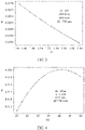
- FIG. 2 is a schematic diagram of a parameter change in the first HUD system.
- a vertical coordinate indicates the included angle ⁇ between the two virtual images and the human eye.
- a horizontal coordinate indicates the distance d1 from the first virtual image to the first windshield surface 103a.
- FIG. 3 is a schematic diagram of a parameter change in a second HUD system.
- a vertical coordinate indicates the included angle ⁇ between the two virtual images and the human eye.
- a horizontal coordinate indicates the refractive index n of the windshield.
- FIG. 4 is a schematic diagram of a parameter change in a third HUD system.
- a vertical coordinate indicates the included angle ⁇ between the two virtual images and the human eye.
- a horizontal coordinate indicates ⁇ 1.
- FIG. 5 is a schematic diagram of a parameter change in a fourth HUD system.
- a vertical coordinate indicates the included angle ⁇ between the two virtual images and the human eye.
- a horizontal coordinate indicates the thickness h of the windshield.
- the foregoing parameter d1 is determined by a focal length of the optical element 102 and a distance between the picture generation unit 101 and the optical element 102. For example, if the distance between the picture generation unit 101 and the optical element 102 is less than the focal length of the optical element 102, a magnified virtual image may be obtained, and a distance between the virtual image and the human eye is relatively long. Therefore, the foregoing parameter d1 can be changed by adjusting the distance between the picture generation unit 101 and the optical element 102 and/or the focal length of the optical element 102.
- FIG. 6 is a structural diagram of the second HUD system according to an embodiment of this application.
- the HUD system shown in FIG. 6 further includes a first driving apparatus 104 and/or a second driving apparatus 105.
- the first driving apparatus 104 is configured to adjust a position of the picture generation unit 101.
- the second driving apparatus 105 is configured to adjust a position of the optical element 102.
- the distance between the picture generation unit 101 and the optical element 102 can be changed by using the first driving apparatus 104 and/or the second driving apparatus 105, to adjust the foregoing parameter d1.
- focal lengths of the optical elements 102 may alternatively be dynamically adjusted.
- the optical element 102 is a liquid crystal on silicon (Liquid Crystal on Silicon, LCOS).
- LCOS Liquid Crystal on Silicon
- a focal length of the LCOS may be changed by loading different modulation information on the LCOS, to adjust the foregoing parameter d1.
- the first driving apparatus 104 may drive the picture generation unit 101 to rotate, to change an angle of a light beam incident on the optical element 102, thereby implementing adjustment of the foregoing parameter ⁇ 1.
- the second driving apparatus 105 may drive the optical element 102 to rotate, to change an angle of a light beam incident on the first windshield surface 103a, thereby implementing adjustment of the foregoing parameter ⁇ 1.
- a temperature of the windshield 103 may be changed by using a temperature adjustment apparatus, to change the refractive index n of the windshield.
- a voltage loaded on the windshield 103 is changed by using a power supply to change the refractive index n of the windshield.
- the optical element 102 may be a reflector, such as a freeform mirror, an aspherical mirror, a reflective LCOS, or a diffractive optical element (Diffractive Optical Element, DOE).
- a specific optical path is shown in FIG. 1 .
- the optical element 102 may be a lens, a transmissive LCOS, or the like.
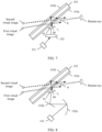
- FIG. 7 is a structural diagram of the third HUD system according to an embodiment of this application.
- FIG. 8 is a structural diagram of the fourth HUD system according to an embodiment of this application.
- the optical element 102 includes a first reflection element 102a and a second reflection element 102b.
- the light beam transmitted by the picture generation unit 101 is successively reflected by the first reflection element 102a and the second reflection element 102b and then is directed to the first windshield surface 103a.
- the windshield 103 is a sandwich structure, that is, the first windshield surface 103a and the second windshield surface 103b are bonded together by using a polymer.
- the picture generated by the PGU forms two virtual images in front of the windshield.
- the included angle between the two virtual images and the human eye is related to a plurality of parameters (for example, the thickness of the windshield, the refractive index of the windshield, the coangle of the incident angle, on the first windshield surface, of the light beam directed by the optical element to the first windshield surface, and the distance between the first virtual image and the human eye).
- the included angle between the two virtual images and the human eye may be less than the preset angle (for example, the resolution of the human eye) by adjusting the foregoing listed parameters. Then, the human eye cannot distinguish between the two virtual images, so that visual interference to the human eye caused by a ghost image of the two virtual images can be effectively eliminated.
- FIG. 9 is a schematic diagram of an image display method based on an HUD system according to an embodiment.
- the HUD system includes a windshield, a PGU, and an optical element, and the windshield includes a first windshield surface and a second windshield surface.
- the image display method includes:
- the light beam after reflection by the first windshield surface, the light beam forms a first virtual image with the picture.
- the second windshield surface reflects a light beam refracted from the first windshield surface to the first windshield surface.
- the first windshield surface refracts a light beam reflected from the second windshield surface to the human eye for receiving.
- the light beam After reflection by the second windshield surface and refraction by the first windshield surface, the light beam forms a second virtual image with the picture.
- the first direction is a direction from the first virtual image to the human eye
- the second direction is a direction from the second virtual image to the human eye
- the HUD system further includes a first driving apparatus and/or a second driving apparatus.
- the method further includes the following steps:
- the first driving apparatus adjusts a position of the PGU, so that the PGU is close to or away from the optical element; and the second driving apparatus adjusts a position of the optical element, so that the optical element is close to or away from the PGU.
- the method further includes the following steps:
- the first driving apparatus drives the PGU to rotate, to adjust a size of the coangle; and the second driving apparatus drives the optical element to rotate, to adjust the size of the coangle.
- the distance between the first virtual image and the human eye is equal to a sum of a first distance and a second distance.
- the first distance is a distance between the first virtual image and the target position on the first windshield surface
- the second distance is a distance between the target position on the first windshield surface and the human eye.
- the method further includes: changing the first distance by adjusting a focal length of the optical element and a distance between the PGU and the optical element.
- the HUD system in this embodiment may be specifically the HUD system in the embodiments shown in FIG. 1 , FIG. 6 , FIG. 7, and FIG. 8 . Details are not described herein again.
Landscapes
- Engineering & Computer Science (AREA)
- Physics & Mathematics (AREA)
- Chemical & Material Sciences (AREA)
- Combustion & Propulsion (AREA)
- Transportation (AREA)
- Mechanical Engineering (AREA)
- General Physics & Mathematics (AREA)
- Optics & Photonics (AREA)
- Instrument Panels (AREA)
Applications Claiming Priority (2)
| Application Number | Priority Date | Filing Date | Title |
|---|---|---|---|
| CN202010413886.8A CN113671698B (zh) | 2020-05-15 | 2020-05-15 | 一种抬头显示系统和基于抬头显示系统的图像显示方法 |
| PCT/CN2021/092081 WO2021227944A1 (fr) | 2020-05-15 | 2021-05-07 | Système d'affichage tête haute et procédé d'affichage d'image basé sur le système d'affichage tête haute |
Publications (2)
| Publication Number | Publication Date |
|---|---|
| EP4137873A1 true EP4137873A1 (fr) | 2023-02-22 |
| EP4137873A4 EP4137873A4 (fr) | 2023-10-25 |
Family
ID=78526436
Family Applications (1)
| Application Number | Title | Priority Date | Filing Date |
|---|---|---|---|
| EP21804282.8A Pending EP4137873A4 (fr) | 2020-05-15 | 2021-05-07 | Système d'affichage tête haute et procédé d'affichage d'image basé sur le système d'affichage tête haute |
Country Status (4)
| Country | Link |
|---|---|
| US (1) | US20230075619A1 (fr) |
| EP (1) | EP4137873A4 (fr) |
| CN (2) | CN114355610B (fr) |
| WO (1) | WO2021227944A1 (fr) |
Families Citing this family (4)
| Publication number | Priority date | Publication date | Assignee | Title |
|---|---|---|---|---|
| CN116804798A (zh) * | 2022-03-18 | 2023-09-26 | 华为技术有限公司 | 投影装置和交通工具 |
| CN114740627B (zh) * | 2022-05-25 | 2023-07-25 | 福耀玻璃工业集团股份有限公司 | 抬头显示系统及其设计方法 |
| CN116061654A (zh) * | 2022-05-31 | 2023-05-05 | 华为技术有限公司 | 一种风挡玻璃、显示系统及交通工具 |
| CN115128815B (zh) * | 2022-08-29 | 2022-12-20 | 泽景(西安)汽车电子有限责任公司 | 一种图像展示方法、装置、电子设备及存储介质 |
Family Cites Families (16)
| Publication number | Priority date | Publication date | Assignee | Title |
|---|---|---|---|---|
| US5013134A (en) * | 1989-09-28 | 1991-05-07 | Hughes Aircraft Company | Ghost-free automotive head-up display employing a wedged windshield |
| EP1093006A4 (fr) * | 1998-06-03 | 2005-06-29 | Nippon Sheet Glass Co Ltd | Dispositif de visualisation tete haute |
| JP4914799B2 (ja) * | 2006-11-13 | 2012-04-11 | 矢崎総業株式会社 | ウインドシールド及びヘッドアップディスプレイユニット |
| JP5802002B2 (ja) * | 2010-09-13 | 2015-10-28 | 矢崎総業株式会社 | ヘッドアップディスプレイ |
| CN104880825B (zh) * | 2015-05-15 | 2017-04-19 | 中国计量学院 | 一种平视显示的重影消除方法 |
| JP2016224080A (ja) * | 2015-05-26 | 2016-12-28 | 株式会社オキサイド | 光コンバイナ、投影型虚像視ディスプレイ、設計プログラムおよび設計方法 |
| CN108027508B (zh) * | 2015-09-30 | 2020-10-20 | 麦克赛尔株式会社 | 显示装置和显示像投影方法以及平视显示器 |
| CN106483664B (zh) * | 2016-12-22 | 2023-08-04 | 深圳点石创新科技有限公司 | 抬头显示装置及装有该抬头显示装置的车辆 |
| CN206615076U (zh) * | 2017-02-14 | 2017-11-07 | 深圳前海智云谷科技有限公司 | 一种分体式抬头显示装置 |
| CN109387940A (zh) * | 2017-08-11 | 2019-02-26 | 东莞创奕电子科技有限公司 | 使用普通风挡的显示装置及其车用抬头显示系统 |
| CN107703633A (zh) * | 2017-10-30 | 2018-02-16 | 苏州车萝卜汽车电子科技有限公司 | 风挡式抬头显示装置以及削弱重影的方法 |
| CN207752232U (zh) * | 2017-10-30 | 2018-08-21 | 苏州车萝卜汽车电子科技有限公司 | 风挡式抬头显示装置 |
| CN108594438A (zh) * | 2018-06-19 | 2018-09-28 | 惠州市华阳多媒体电子有限公司 | 一种可配合偏光墨镜使用并消除重影的hud光路系统 |
| CN108873349A (zh) * | 2018-07-16 | 2018-11-23 | 惠州市华阳多媒体电子有限公司 | 一种采用楔形半反镜消除重影的chud光路系统 |
| CN110794580B (zh) * | 2018-08-03 | 2022-04-05 | 深圳前海智云谷科技有限公司 | 汽车抬头显示系统及其安装方法和消除重影的方法 |
| CN112969952B (zh) * | 2018-11-06 | 2023-06-30 | 中央硝子株式会社 | 平视显示器装置 |
-
2020
- 2020-05-15 CN CN202111567190.1A patent/CN114355610B/zh active Active
- 2020-05-15 CN CN202010413886.8A patent/CN113671698B/zh active Active
-
2021
- 2021-05-07 EP EP21804282.8A patent/EP4137873A4/fr active Pending
- 2021-05-07 WO PCT/CN2021/092081 patent/WO2021227944A1/fr unknown
-
2022
- 2022-11-14 US US17/986,752 patent/US20230075619A1/en active Pending
Also Published As
| Publication number | Publication date |
|---|---|
| EP4137873A4 (fr) | 2023-10-25 |
| CN113671698A (zh) | 2021-11-19 |
| US20230075619A1 (en) | 2023-03-09 |
| WO2021227944A1 (fr) | 2021-11-18 |
| CN114355610B (zh) | 2023-07-18 |
| CN113671698B (zh) | 2022-07-29 |
| CN114355610A (zh) | 2022-04-15 |
Similar Documents
| Publication | Publication Date | Title |
|---|---|---|
| EP4137873A1 (fr) | Système d'affichage tête haute et procédé d'affichage d'image basé sur le système d'affichage tête haute | |
| JP6650584B2 (ja) | ヘッドアップディスプレイおよびヘッドアップディスプレイを搭載した移動体 | |
| JP5594272B2 (ja) | ヘッドアップディスプレイ装置 | |
| EP3415974B1 (fr) | Dispositif d'affichage et afficheur tête haute | |
| US11561396B2 (en) | Head-up display device and transportation device | |
| EP3415973B1 (fr) | Dispositif d'affichage et affichage tête haute | |
| TWI494603B (zh) | 可攜式抬頭顯示裝置 | |
| JP2018146882A (ja) | 画像投写装置 | |
| US11226490B2 (en) | Virtual image display device | |
| JP2023532072A (ja) | 車両用ヘッドアップディスプレイ(hud) | |
| JP6593461B2 (ja) | 虚像表示装置 | |
| WO2016208194A1 (fr) | Affichage tête haute et corps en déplacement équipé d'un affichage tête haute | |
| CN103631009A (zh) | 影像分割式虚像显示装置 | |
| JP2017142284A (ja) | 表示装置及びヘッドアップディスプレイ | |
| TW201409077A (zh) | 影像分割式虛像顯示裝置 | |
| JP2018146883A (ja) | 画像投写装置 | |
| US11841504B2 (en) | Image display device with rotatably held image forming optical unit | |
| JP2017227681A (ja) | ヘッドアップディスプレイ装置 | |
| JP2020073963A (ja) | 虚像表示装置 | |
| JP2021096284A (ja) | 画像表示装置 | |
| US20240061240A1 (en) | Air floating video display apparatus and light source | |
| JP7491156B2 (ja) | ヘッドアップディスプレイ装置 | |
| EP3789227B1 (fr) | Afficheur de véhicule | |
| EP3534202B1 (fr) | Dispositif d'affichage d'image virtuelle | |
| WO2019240230A1 (fr) | Dispositif d'affichage d'image virtuelle |
Legal Events
| Date | Code | Title | Description |
|---|---|---|---|
| STAA | Information on the status of an ep patent application or granted ep patent |
Free format text: STATUS: THE INTERNATIONAL PUBLICATION HAS BEEN MADE |
|
| PUAI | Public reference made under article 153(3) epc to a published international application that has entered the european phase |
Free format text: ORIGINAL CODE: 0009012 |
|
| STAA | Information on the status of an ep patent application or granted ep patent |
Free format text: STATUS: REQUEST FOR EXAMINATION WAS MADE |
|
| 17P | Request for examination filed |
Effective date: 20221118 |
|
| AK | Designated contracting states |
Kind code of ref document: A1 Designated state(s): AL AT BE BG CH CY CZ DE DK EE ES FI FR GB GR HR HU IE IS IT LI LT LU LV MC MK MT NL NO PL PT RO RS SE SI SK SM TR |
|
| DAV | Request for validation of the european patent (deleted) | ||
| DAX | Request for extension of the european patent (deleted) | ||
| A4 | Supplementary search report drawn up and despatched |
Effective date: 20230926 |
|
| RIC1 | Information provided on ipc code assigned before grant |
Ipc: B60J 3/00 20060101ALI20230920BHEP Ipc: B60R 1/00 20220101ALI20230920BHEP Ipc: G02B 27/01 20060101AFI20230920BHEP |