EP4137692A1 - Composant d'arbre et procédé de fabrication d'un composant d'arbre - Google Patents
Composant d'arbre et procédé de fabrication d'un composant d'arbre Download PDFInfo
- Publication number
- EP4137692A1 EP4137692A1 EP22187797.0A EP22187797A EP4137692A1 EP 4137692 A1 EP4137692 A1 EP 4137692A1 EP 22187797 A EP22187797 A EP 22187797A EP 4137692 A1 EP4137692 A1 EP 4137692A1
- Authority
- EP
- European Patent Office
- Prior art keywords
- shaft component
- fibers
- shaft
- fiber
- regions
- Prior art date
- Legal status (The legal status is an assumption and is not a legal conclusion. Google has not performed a legal analysis and makes no representation as to the accuracy of the status listed.)
- Pending
Links
- 238000004519 manufacturing process Methods 0.000 title claims abstract description 9
- 239000000835 fiber Substances 0.000 claims abstract description 124
- 238000000034 method Methods 0.000 claims abstract description 16
- 229920002430 Fibre-reinforced plastic Polymers 0.000 claims abstract description 12
- 239000011151 fibre-reinforced plastic Substances 0.000 claims abstract description 12
- 239000000203 mixture Substances 0.000 claims abstract description 10
- 239000000463 material Substances 0.000 claims description 15
- 239000011159 matrix material Substances 0.000 claims description 11
- 238000011144 upstream manufacturing Methods 0.000 claims description 8
- 239000011347 resin Substances 0.000 claims description 7
- 229920005989 resin Polymers 0.000 claims description 7
- 229920000049 Carbon (fiber) Polymers 0.000 claims description 5
- 239000004917 carbon fiber Substances 0.000 claims description 5
- 229910052751 metal Inorganic materials 0.000 claims description 5
- 239000002184 metal Substances 0.000 claims description 5
- 239000000919 ceramic Substances 0.000 claims description 3
- 229920002994 synthetic fiber Polymers 0.000 claims description 3
- 239000012209 synthetic fiber Substances 0.000 claims description 3
- 238000009954 braiding Methods 0.000 claims description 2
- 230000008859 change Effects 0.000 claims description 2
- 238000009728 tailored fiber placement Methods 0.000 claims description 2
- 238000004804 winding Methods 0.000 claims description 2
- 239000004760 aramid Substances 0.000 claims 1
- 229920006231 aramid fiber Polymers 0.000 claims 1
- 239000002131 composite material Substances 0.000 description 25
- 238000013461 design Methods 0.000 description 17
- 238000005452 bending Methods 0.000 description 15
- 230000000670 limiting effect Effects 0.000 description 6
- 230000009467 reduction Effects 0.000 description 6
- 230000002829 reductive effect Effects 0.000 description 5
- RTAQQCXQSZGOHL-UHFFFAOYSA-N Titanium Chemical compound [Ti] RTAQQCXQSZGOHL-UHFFFAOYSA-N 0.000 description 4
- 238000002485 combustion reaction Methods 0.000 description 4
- 239000010936 titanium Substances 0.000 description 4
- 229910052719 titanium Inorganic materials 0.000 description 4
- 230000005540 biological transmission Effects 0.000 description 3
- 230000006835 compression Effects 0.000 description 3
- 238000007906 compression Methods 0.000 description 3
- 230000008878 coupling Effects 0.000 description 3
- 238000010168 coupling process Methods 0.000 description 3
- 238000005859 coupling reaction Methods 0.000 description 3
- 230000000694 effects Effects 0.000 description 3
- 229910001148 Al-Li alloy Inorganic materials 0.000 description 2
- JFBZPFYRPYOZCQ-UHFFFAOYSA-N [Li].[Al] Chemical compound [Li].[Al] JFBZPFYRPYOZCQ-UHFFFAOYSA-N 0.000 description 2
- 229910052782 aluminium Inorganic materials 0.000 description 2
- XAGFODPZIPBFFR-UHFFFAOYSA-N aluminium Chemical compound [Al] XAGFODPZIPBFFR-UHFFFAOYSA-N 0.000 description 2
- 229920003235 aromatic polyamide Polymers 0.000 description 2
- 230000004323 axial length Effects 0.000 description 2
- 239000002657 fibrous material Substances 0.000 description 2
- 239000000446 fuel Substances 0.000 description 2
- 239000001989 lithium alloy Substances 0.000 description 2
- VNWKTOKETHGBQD-UHFFFAOYSA-N methane Chemical compound C VNWKTOKETHGBQD-UHFFFAOYSA-N 0.000 description 2
- 230000033772 system development Effects 0.000 description 2
- 238000003466 welding Methods 0.000 description 2
- 229910000831 Steel Inorganic materials 0.000 description 1
- 239000000853 adhesive Substances 0.000 description 1
- 230000001070 adhesive effect Effects 0.000 description 1
- 229910045601 alloy Inorganic materials 0.000 description 1
- 239000000956 alloy Substances 0.000 description 1
- 230000009286 beneficial effect Effects 0.000 description 1
- 230000007423 decrease Effects 0.000 description 1
- 230000008030 elimination Effects 0.000 description 1
- 238000003379 elimination reaction Methods 0.000 description 1
- 239000011156 metal matrix composite Substances 0.000 description 1
- 230000004048 modification Effects 0.000 description 1
- 238000012986 modification Methods 0.000 description 1
- 238000005457 optimization Methods 0.000 description 1
- 238000012856 packing Methods 0.000 description 1
- 230000001141 propulsive effect Effects 0.000 description 1
- 230000001681 protective effect Effects 0.000 description 1
- 230000000717 retained effect Effects 0.000 description 1
- 238000004513 sizing Methods 0.000 description 1
- 230000003068 static effect Effects 0.000 description 1
- 239000010959 steel Substances 0.000 description 1
- 230000007704 transition Effects 0.000 description 1
Images


Classifications
-
- F—MECHANICAL ENGINEERING; LIGHTING; HEATING; WEAPONS; BLASTING
- F02—COMBUSTION ENGINES; HOT-GAS OR COMBUSTION-PRODUCT ENGINE PLANTS
- F02C—GAS-TURBINE PLANTS; AIR INTAKES FOR JET-PROPULSION PLANTS; CONTROLLING FUEL SUPPLY IN AIR-BREATHING JET-PROPULSION PLANTS
- F02C7/00—Features, components parts, details or accessories, not provided for in, or of interest apart form groups F02C1/00 - F02C6/00; Air intakes for jet-propulsion plants
- F02C7/36—Power transmission arrangements between the different shafts of the gas turbine plant, or between the gas-turbine plant and the power user
-
- B—PERFORMING OPERATIONS; TRANSPORTING
- B29—WORKING OF PLASTICS; WORKING OF SUBSTANCES IN A PLASTIC STATE IN GENERAL
- B29C—SHAPING OR JOINING OF PLASTICS; SHAPING OF MATERIAL IN A PLASTIC STATE, NOT OTHERWISE PROVIDED FOR; AFTER-TREATMENT OF THE SHAPED PRODUCTS, e.g. REPAIRING
- B29C70/00—Shaping composites, i.e. plastics material comprising reinforcements, fillers or preformed parts, e.g. inserts
- B29C70/04—Shaping composites, i.e. plastics material comprising reinforcements, fillers or preformed parts, e.g. inserts comprising reinforcements only, e.g. self-reinforcing plastics
- B29C70/28—Shaping operations therefor
-
- F—MECHANICAL ENGINEERING; LIGHTING; HEATING; WEAPONS; BLASTING
- F01—MACHINES OR ENGINES IN GENERAL; ENGINE PLANTS IN GENERAL; STEAM ENGINES
- F01D—NON-POSITIVE DISPLACEMENT MACHINES OR ENGINES, e.g. STEAM TURBINES
- F01D5/00—Blades; Blade-carrying members; Heating, heat-insulating, cooling or antivibration means on the blades or the members
- F01D5/02—Blade-carrying members, e.g. rotors
- F01D5/06—Rotors for more than one axial stage, e.g. of drum or multiple disc type; Details thereof, e.g. shafts, shaft connections
-
- F—MECHANICAL ENGINEERING; LIGHTING; HEATING; WEAPONS; BLASTING
- F16—ENGINEERING ELEMENTS AND UNITS; GENERAL MEASURES FOR PRODUCING AND MAINTAINING EFFECTIVE FUNCTIONING OF MACHINES OR INSTALLATIONS; THERMAL INSULATION IN GENERAL
- F16C—SHAFTS; FLEXIBLE SHAFTS; ELEMENTS OR CRANKSHAFT MECHANISMS; ROTARY BODIES OTHER THAN GEARING ELEMENTS; BEARINGS
- F16C3/00—Shafts; Axles; Cranks; Eccentrics
- F16C3/02—Shafts; Axles
- F16C3/026—Shafts made of fibre reinforced resin
-
- B—PERFORMING OPERATIONS; TRANSPORTING
- B29—WORKING OF PLASTICS; WORKING OF SUBSTANCES IN A PLASTIC STATE IN GENERAL
- B29L—INDEXING SCHEME ASSOCIATED WITH SUBCLASS B29C, RELATING TO PARTICULAR ARTICLES
- B29L2031/00—Other particular articles
- B29L2031/748—Machines or parts thereof not otherwise provided for
- B29L2031/75—Shafts
-
- F—MECHANICAL ENGINEERING; LIGHTING; HEATING; WEAPONS; BLASTING
- F05—INDEXING SCHEMES RELATING TO ENGINES OR PUMPS IN VARIOUS SUBCLASSES OF CLASSES F01-F04
- F05D—INDEXING SCHEME FOR ASPECTS RELATING TO NON-POSITIVE-DISPLACEMENT MACHINES OR ENGINES, GAS-TURBINES OR JET-PROPULSION PLANTS
- F05D2240/00—Components
- F05D2240/60—Shafts
-
- F—MECHANICAL ENGINEERING; LIGHTING; HEATING; WEAPONS; BLASTING
- F05—INDEXING SCHEMES RELATING TO ENGINES OR PUMPS IN VARIOUS SUBCLASSES OF CLASSES F01-F04
- F05D—INDEXING SCHEME FOR ASPECTS RELATING TO NON-POSITIVE-DISPLACEMENT MACHINES OR ENGINES, GAS-TURBINES OR JET-PROPULSION PLANTS
- F05D2260/00—Function
- F05D2260/40—Transmission of power
- F05D2260/403—Transmission of power through the shape of the drive components
- F05D2260/4031—Transmission of power through the shape of the drive components as in toothed gearing
- F05D2260/40311—Transmission of power through the shape of the drive components as in toothed gearing of the epicyclical, planetary or differential type
-
- F—MECHANICAL ENGINEERING; LIGHTING; HEATING; WEAPONS; BLASTING
- F05—INDEXING SCHEMES RELATING TO ENGINES OR PUMPS IN VARIOUS SUBCLASSES OF CLASSES F01-F04
- F05D—INDEXING SCHEME FOR ASPECTS RELATING TO NON-POSITIVE-DISPLACEMENT MACHINES OR ENGINES, GAS-TURBINES OR JET-PROPULSION PLANTS
- F05D2300/00—Materials; Properties thereof
- F05D2300/60—Properties or characteristics given to material by treatment or manufacturing
- F05D2300/603—Composites; e.g. fibre-reinforced
- F05D2300/6034—Orientation of fibres, weaving, ply angle
-
- F—MECHANICAL ENGINEERING; LIGHTING; HEATING; WEAPONS; BLASTING
- F05—INDEXING SCHEMES RELATING TO ENGINES OR PUMPS IN VARIOUS SUBCLASSES OF CLASSES F01-F04
- F05D—INDEXING SCHEME FOR ASPECTS RELATING TO NON-POSITIVE-DISPLACEMENT MACHINES OR ENGINES, GAS-TURBINES OR JET-PROPULSION PLANTS
- F05D2300/00—Materials; Properties thereof
- F05D2300/60—Properties or characteristics given to material by treatment or manufacturing
- F05D2300/614—Fibres or filaments
-
- F—MECHANICAL ENGINEERING; LIGHTING; HEATING; WEAPONS; BLASTING
- F16—ENGINEERING ELEMENTS AND UNITS; GENERAL MEASURES FOR PRODUCING AND MAINTAINING EFFECTIVE FUNCTIONING OF MACHINES OR INSTALLATIONS; THERMAL INSULATION IN GENERAL
- F16C—SHAFTS; FLEXIBLE SHAFTS; ELEMENTS OR CRANKSHAFT MECHANISMS; ROTARY BODIES OTHER THAN GEARING ELEMENTS; BEARINGS
- F16C2208/00—Plastics; Synthetic resins, e.g. rubbers
- F16C2208/02—Plastics; Synthetic resins, e.g. rubbers comprising fillers, fibres
-
- F—MECHANICAL ENGINEERING; LIGHTING; HEATING; WEAPONS; BLASTING
- F16—ENGINEERING ELEMENTS AND UNITS; GENERAL MEASURES FOR PRODUCING AND MAINTAINING EFFECTIVE FUNCTIONING OF MACHINES OR INSTALLATIONS; THERMAL INSULATION IN GENERAL
- F16C—SHAFTS; FLEXIBLE SHAFTS; ELEMENTS OR CRANKSHAFT MECHANISMS; ROTARY BODIES OTHER THAN GEARING ELEMENTS; BEARINGS
- F16C2240/00—Specified values or numerical ranges of parameters; Relations between them
- F16C2240/30—Angles, e.g. inclinations
-
- F—MECHANICAL ENGINEERING; LIGHTING; HEATING; WEAPONS; BLASTING
- F16—ENGINEERING ELEMENTS AND UNITS; GENERAL MEASURES FOR PRODUCING AND MAINTAINING EFFECTIVE FUNCTIONING OF MACHINES OR INSTALLATIONS; THERMAL INSULATION IN GENERAL
- F16C—SHAFTS; FLEXIBLE SHAFTS; ELEMENTS OR CRANKSHAFT MECHANISMS; ROTARY BODIES OTHER THAN GEARING ELEMENTS; BEARINGS
- F16C2360/00—Engines or pumps
- F16C2360/23—Gas turbine engines
-
- Y—GENERAL TAGGING OF NEW TECHNOLOGICAL DEVELOPMENTS; GENERAL TAGGING OF CROSS-SECTIONAL TECHNOLOGIES SPANNING OVER SEVERAL SECTIONS OF THE IPC; TECHNICAL SUBJECTS COVERED BY FORMER USPC CROSS-REFERENCE ART COLLECTIONS [XRACs] AND DIGESTS
- Y02—TECHNOLOGIES OR APPLICATIONS FOR MITIGATION OR ADAPTATION AGAINST CLIMATE CHANGE
- Y02T—CLIMATE CHANGE MITIGATION TECHNOLOGIES RELATED TO TRANSPORTATION
- Y02T50/00—Aeronautics or air transport
- Y02T50/60—Efficient propulsion technologies, e.g. for aircraft
Definitions
- the present invention relates to a shaft component, e.g. for a gas turbine engine, more particularly a shaft component that can be connected or is connected to the input or output side of a gear box of a gas turbine aircraft engine.
- epicyclic gear boxes In gas turbine engines, in particular in geared fan engines of aircraft, epicyclic gear boxes (planetary gear boxes) are used to reduce the relatively high speeds of a turbine for driving a fan of the engine. It is known in principle, for example from United States patent application US 2009/0038435 A1 to use composite materials in connection with gear boxes.
- the present invention provides a shaft component, a method for producing a shaft component, and a gas turbine engine, as set out in the appended claims.
- a shaft component which in particular can be connected or is connected to the input or output side of a gear box in a gas turbine engine, in particular an aircraft engine.
- the shaft component has at least two regions comprising fiber reinforced plastic, with fibers and/or their matrix in the at least two regions differing in their composition, their geometric properties, their density, their radial position, their axial position and/or in their fiber orientation in the shaft component.
- the complete set of fiber orientations within a composite often changes by layer and is generally referred to as a "Plybook" even if the method of manufacture is not the incremental laying on of sheets (also called plys) of fiber in different directions.
- the fiber directions are normally specified relative to a defined co-ordinate frame, which for a shaft is normally taken to be a cylindrical one aligned to the shaft axis and located at a center point of the shaft. This gives radial, tangential (or circumferential) and axial directions.
- 3D woven fiber composites there is not normally any fibers arranged in the radial direction through a shaft section, which leaves the fibers all lying on cylinders or cones (or transitions between) in a 2D sense.
- the fiber direction is then completely defined by one angle - in this case measured to the axial axis projected onto the fiber cylinder or cone.
- 0° refers to a fiber completely aligned to the axial shaft direction
- 90° refers to a fiber completely aligned to circumferential direction.
- This regional design allows an implementation of tailored flexibility while managing dynamic behavior of the shaft component.
- the composite design will respect the criteria to avoid shaft whirl and undesirable vibration modes, possibly leading to a modification from the optimum solution for transmitting the torque and maintaining the lateral stiffness.
- the regional design also enables reduced space requirement due to elimination or reduction of geometric convolutions, such as bellows. Also, a reduction in weight can be achieved due to use of less dense material and more compact shaft design (reduced material due to removed convolutions).
- the fibers are arranged in an angular range of +/-40° to 50°, in particular of +/-42° to 48°, most particularly +/-45°, in relation to the main axis of rotation of the shaft component.
- the angular values given here, and elsewhere are the angular directions which are predominantly present in the fiber layers.
- transitional zones are designed in such a way that the majority (>90%) of the fiber angle change is contained within an axial extant no greater than 10% of the shorter of the two adjacent regions.
- This angular design is effective for balancing the internally generated axial loads created by the torque transmission through the composite.
- Using this symmetrically paired orientation of fibers produces the most efficient composite design to transmit torque loads. All the fibers deviate from the 0° direction by about 45°, which allows all the fibers to weakly contribute to the bending and axial stiffnesses of these sections, resulting in medium bending and axial stiffnesses.
- the fibers are predominantly arranged in an angular range about 0° in relation to the main axis of rotation of the shaft component. This means that in this one region the fibers are arranged aligned with the rotational axis of the shaft component. This fiber orientation maximizes both the axial stiffness of the shaft and the bending stiffness of the shaft.
- the fibers are arranged in an angular range about 90° in relation to the main axis of rotation of the shaft component. Angles above 90° are just the opposite hand of the angles below 90°.
- the shaft component has a non-constant or non-uniform diameter along the axis of rotation.
- a shaft component is an undulant shaft having bellow sections.
- the use of composite fibers with the angles mentioned above will reduce the need for undulations or bellows.
- the shaft can be completely smooth, but in some other shaft embodiments which have requirements of very low bending stiffness, the undulations or bellows might need to be retained. However, the undulations or bellows will be of much smaller height.
- the ratios between resin and fibers are normally characterized using the volume fiber fraction of the total composite, with a typical value in the range 55% to 65%. While it is possible with some composite methods of manufacture to create lower fiber fractions to intentionally give reduced stiffness properties, this is typically part of the material system development and not explicitly part of the design.
- Fiber bundle counts and individual fiber diameters are different in the at least two different regions.
- Common organic composite method of manufacture utilize very small diameter fibers to allow creation of the curved surfaces contained within the final products without damaging the fibers, in the range of 4 to 10 microns. These fibers often create composites which have significantly lower stiffness and strength properties under the effect of compressive loads compared to under tensile loads. Torque transmission through shafts in essence creates a pair of balanced tension and compression loads within the shaft and this difference between tensile and compressive behavior is hence undesirable.
- Use of both larger diameter fibers and/or larger bundles of fiber in the composite manufacturing process can reduce the difference between the tensile and compressive properties; this is typically part of the material system development and not explicitly part of the design.
- the angle of the fiber arrangement varies radially in the at least two different regions. This means that the wall of the shaft component can comprise fibers arranged in different angular patterns.
- At least one woven material in particular a ribbon is used in least one of the two different regions.
- the use of woven materials is especially beneficial on the composite outer layers, as the fibers are already tied together before the curing of the composite.
- the ratio between the largest diameter and the smallest diameter of the shaft component is less than 1.1.
- At least one first region comprises fibers with orientations going from 40° to 50° to 65° to 90° and at least one second region with fibers with orientations going from 0° to 50° and the at least one first region being adjacent to the at least one second region.
- the shaft component in one embodiment is designed as part of a drive shaft for a fan.
- the fiber-reinforced plastic can e.g. comprise carbon fibers, metal filaments, synthetic fibers, in particular aramids and/or ceramic fibers.
- a method for producing a shaft component which can be connected or is connected to the input or output side of a gear box in a gas turbine engine, wherein fibers are incorporated in a matrix, the fibers and/or their matrix being incorporated in the shaft component so that in at least two regions differ in their composition, their geometric properties, their density, their radial position, their axial position and/or in their fiber orientation in the shaft component.
- a winding method, a braiding method, a Tailored Fiber Placement (TFP) method or a combination of two or more of those methods is used for incorporating the fibers in the matrix or in the shaft component.
- the fiber-reinforced plastic comprises carbon fibers, metal filaments and/or synthetic fibers.
- the fiber-reinforced plastic comprises aramids and/or ceramic fibers.
- a gas turbine engine for an aircraft comprising: an engine core comprising a turbine, a compressor, and a core shaft connecting the turbine to the compressor; a fan, which is positioned upstream of the engine core, wherein the fan comprises a plurality of fan blades; and a gear box, which can be driven by the core shaft, wherein the fan can be driven by means of the gear box at a lower rotational speed than the core shaft, wherein a shaft component according to the first aspect is connected to the gear box as part of a drive shaft for the fan.
- the shaft component is connected to the gear box on the output side of the gear box.
- the gas turbine engine may be an aircraft engine.
- a gas turbine engine may comprise an engine core comprising a turbine, a combustor, a compressor, and a core shaft connecting the turbine to the compressor.
- Such a gas turbine engine may comprise a fan (with fan blades) which is positioned upstream of the engine core.
- the gas turbine engine may comprise a gear box which is driven via the core shaft and the output of which drives the fan in such a way that it has a lower rotational speed than the core shaft.
- the input to the gear box may be effected directly from the core shaft, or indirectly via the core shaft, for example via a spur shaft and/or spur gear.
- the core shaft may be rigidly connected to the turbine and the compressor, such that the turbine and compressor rotate at the same rotational speed (with the fan rotating at a lower rotational speed).
- the gas turbine engine as described and/or claimed herein may have any suitable general architecture.
- the gas turbine engine may have any desired number of shafts that connect turbines and compressors, for example one, two or three shafts.
- the turbine connected to the core shaft may be a first turbine
- the compressor connected to the core shaft may be a first compressor
- the core shaft may be a first core shaft.
- the engine core may further comprise a second turbine, a second compressor, and a second core shaft connecting the second turbine to the second compressor.
- the second turbine, the second compressor, and the second core shaft may be arranged to rotate at a higher speed than the first core shaft.
- the second compressor may be positioned axially downstream of the first compressor.
- the second compressor may be arranged to receive (for example directly receive, for example via a generally annular duct) a flow from the first compressor.
- the gear box may be designed to be driven by the core shaft that is configured to rotate (for example in use) at the lowest rotational speed (for example the first core shaft in the example above).
- the gear box may be designed to be driven only by the core shaft that is configured to rotate (for example in use) at the lowest rotational speed (for example only by the first core shaft and not the second core shaft in the example above).
- the gear box may be designed to be driven by one or more shafts, for example the first and/or second shaft in the example above.
- a combustor may be provided axially downstream of the fan and compressor (or compressors).
- the combustor may be directly downstream of (for example at the exit of) the second compressor if a second compressor is provided.
- the flow at the exit of the compressor may be supplied to the inlet of the second turbine if a second turbine is provided.
- the combustor may be provided upstream of the turbine(s).
- each compressor may comprise any number of stages, for example multiple stages.
- Each stage may comprise a row of rotor blades and a row of stator blades, which may be variable stator blades (i.e. the angle of incidence may be variable).
- the row of rotor blades and the row of stator blades may be axially offset with respect to one another.
- each turbine may comprise any number of stages, for example multiple stages.
- Each stage may comprise a row of rotor blades and a row of stator blades.
- the row of rotor blades and the row of stator blades may be axially offset with respect to one another.
- Each fan blade may have a radial span extending from a root (or a hub) at a radially inner location which is flowed over by gas, or from a position of 0% span, to a tip with a 100% span.
- the ratio of the radius of the fan blade at the hub to the radius of the fan blade at the tip may be less than (or of the order of magnitude of) any of the following: 0.4, 0.39, 0.38, 0.37, 0.36, 0.35, 0.34, 0.33, 0.32, 0.31, 0.3, 0.29, 0.28, 0.27, 0.26 or 0.25.
- the ratio of the radius of the fan blade at the hub to the radius of the fan blade at the tip may be in an inclusive range bounded by any two values in the previous sentence (i.e.
- the values may form upper or lower bounds). These ratios can commonly be referred to as the hub-to-tip ratio.
- the radius at the hub and the radius at the tip may both be measured at the leading edge (or the axially forwardmost edge) of the blade.
- the hub-to-tip ratio refers, of course, to that portion of the fan blade which is flowed over by gas, i.e. the portion radially outside any platform.
- the speed of the fan may vary in operation. Generally, the speed is lower for fans with a larger diameter.
- the rotational speed of the fan under cruise conditions may be less than 2500 rpm, for example less than 2300 rpm.
- the rotational speed of the fan under cruise conditions for an engine having a fan diameter in the range of from 250 cm to 300 cm (for example 250 cm to 280 cm) may also be in the range of from 1700 rpm to 2500 rpm, for example in the range of from 1800 rpm to 2300 rpm, for example in the range of from 1900 rpm to 2100 rpm.
- the speed of the fan under cruise conditions for an engine having a fan diameter in the range of from 320 cm to 380 cm may be in the range of from 1200 rpm to 2000 rpm, for example in the range of from 1300 rpm to 1800 rpm, for example in the range of from 1400 rpm to 1600 rpm.
- a fan tip loading may be defined as dH/U tip 2 .
- dH is the enthalpy rise (for example the average 1-D enthalpy rise) across the fan and U tip is the (translational) speed of the fan tip, for example at the leading edge of the tip (which may be defined as fan tip radius at the leading edge multiplied by angular speed).
- the fan tip loading under cruise conditions may be more than (or of the order of magnitude of): 0.3, 0.31, 0.32, 0.33, 0.34, 0.35, 0.36, 0.37, 0.38, 0.39, or 0.4 (wherein all units in this passage are Jkg -1 K -1 /(ms -1 ) 2 ).
- the fan tip loading may be in an inclusive range bounded by any two of the values in the previous sentence (i.e. the values may form upper or lower bounds).
- Gas turbine engines according to the present invention can have any desired bypass ratio, wherein the bypass ratio is defined as the ratio of the mass flow rate of the flow through the bypass duct to the mass flow rate of the flow through the core under cruise conditions.
- the bypass ratio can be more than (or of the order of magnitude of): 10, 10.5, 11, 11.5, 12, 12.5, 13, 13.5, 14, 14.5, 15, 15.5, 16, 16.5, or 17.
- the bypass ratio may be in an inclusive range bounded by any two of the values in the previous sentence (i.e. the values may form upper or lower bounds).
- the bypass duct may be substantially annular.
- the bypass duct may be radially outside the engine core.
- the radially outer surface of the bypass duct may be defined by an engine nacelle and/or a fan case.
- the overall pressure ratio of a gas turbine engine as described and/or claimed herein may be defined as the ratio of the stagnation pressure upstream of the fan to the stagnation pressure at the exit of the highest pressure compressor (before entry into the combustor).
- the overall pressure ratio of a gas turbine engine as described and/or claimed herein at cruising speed may be greater than (or of the order of): 35, 40, 45, 50, 55, 60, 65, 70, 75.
- the overall pressure ratio may be in an inclusive range bounded by any two of the values in the previous sentence (i.e. the values may form upper or lower bounds).
- the specific thrust of an engine can be defined as the net thrust of the engine divided by the total mass flow through the engine.
- the specific thrust of an engine as described and/or claimed herein under cruise conditions may be less than (or of the order of): 110 N kg -1 s, 105 N kg -1 s, 100 N kg -1 s, 95 N kg -1 s, 90 N kg -1 s, 85 N kg -1 s or 80 N kg -1 s.
- the specific thrust may be in an inclusive range bounded by any two of the values in the previous sentence (i.e. the values may form upper or lower bounds).
- Such engines can be particularly efficient in comparison with conventional gas turbine engines.
- a gas turbine engine as described and/or claimed herein may have any desired maximum thrust.
- a gas turbine as described and/or claimed herein can be capable of generating a maximum thrust of at least (or of the order of): 160 kN, 170 kN, 180 kN, 190 kN, 200 kN, 250 kN, 300 kN, 350 kN, 400 kN, 450 kN, 500 kN or 550 kN.
- the maximum thrust may be in an inclusive range bounded by any two of the values in the previous sentence (i.e. the values may form upper or lower bounds).
- the thrust referred to above may be the maximum net thrust under standard atmospheric conditions at sea level plus 15° C. (ambient pressure 101.3 kPa, temperature 30° C.), with the engine static.
- the temperature of the flow at the entry to the high-pressure turbine can be particularly high.
- This temperature which may be referred to as TET
- TET may be measured at the exit to the combustor, for example immediately upstream of the first turbine blade, which itself may be referred to as a nozzle guide blade.
- the TET may be at least (or of the order of): 1400 K, 1450 K, 1500 K, 1550 K, 1600 K or 1650 K.
- the TET at cruising speed may be in an inclusive range bounded by any two of the values in the previous sentence (i.e. the values may form upper or lower bounds).
- the maximum TET in the use of the engine can be at least (or of the order of), for example: 1700 K, 1750 K, 1800 K, 1850 K, 1900 K, 1950 K or 2000 K.
- the maximum TET may be in an inclusive range bounded by any two of the values in the previous sentence (i.e. the values may form upper or lower bounds).
- the maximum TET can occur, for example, under a high thrust condition, for example under a maximum take-off thrust (MTO) condition.
- MTO maximum take-off thrust
- a fan blade and/or aerofoil portion of a fan blade described and/or claimed herein may be produced from any suitable material or combination of materials.
- at least a part of the fan blade and/or aerofoil may be produced at least in part from a composite, for example a metal matrix composite and/or an organic matrix composite, such as carbon fiber.
- at least a part of the fan blade and/or aerofoil may be produced at least in part from a metal, such as e.g. a titanium based metal or an aluminum based material (such as e.g. an aluminum-lithium alloy) or a steel-based material.
- the fan blade may comprise at least two regions produced using different materials.
- the fan blade may have a protective leading edge, which is produced using a material that is better able to resist impact (for example from birds, ice or other material) than the rest of the blade.
- a leading edge may, for example, be produced using titanium or a titanium-based alloy.
- the fan blade may have a carbon-fiber or aluminum based body (such as an aluminum-lithium alloy) with a titanium leading edge.
- a fan as described and/or claimed herein may comprise a central portion, from which the fan blades may extend, for example in a radial direction.
- the fan blades may be attached to the central portion in any desired manner.
- each fan blade may comprise a fixture which may engage with a corresponding slot in the hub (or disk).
- a fixture may be in the form of a dovetail that may slot into and/or be brought into engagement with a corresponding slot in the hub/disk in order to fix the fan blade to the hub/disk.
- the fan blades may be formed integrally with a central portion. Such an arrangement can be referred to as a blisk or a bling.
- any suitable method can be used to produce such a blisk or such a bling.
- at least a part of the fan blades may be machined from a block and/or at least part of the fan blades may be attached to the hub/disk by welding, such as e.g. linear friction welding.
- variable area nozzle may allow the exit area of the bypass duct to be varied in operation.
- the general principles of the present invention can apply to engines with or without a VAN.
- the fan of a gas turbine as described and/or claimed herein may have any desired number of fan blades, for example 16, 18, 20, or 22 fan blades.
- cruise conditions may mean the cruise conditions of an aircraft to which the gas turbine engine is attached.
- cruise conditions may be conventionally defined as the conditions during the middle part of the flight, for example the conditions experienced by the aircraft and/or the engine between (in terms of time and/or distance) the end of the ascent and the start of the descent.
- FIG. 1 illustrates a gas turbine engine 10 having a main axis of rotation 9.
- the gas turbine engine 10 comprises an air inlet 12 and a fan 23 that generates two air flows: a core air flow A and a bypass air flow B.
- the gas turbine engine 10 comprises a core 11 that receives the core air flow A.
- the engine core 11 comprises a low-pressure compressor 14, a high-pressure compressor 15, a combustion device 16, a high-pressure turbine 17, a low-pressure turbine 19, and a core thrust nozzle 20.
- An engine nacelle 21 surrounds the gas turbine engine 10 and defines a bypass duct 22 and a bypass thrust nozzle 18.
- the bypass air flow B flows through the bypass duct 22.
- the fan 23 is attached to and driven by the low-pressure turbine 19 via a shaft 26 and an epicyclic planetary gear box 30.
- the core air flow A is accelerated and compressed by the low-pressure compressor 14 and directed into the high-pressure compressor 15, where further compression takes place.
- the compressed air exhausted from the high-pressure compressor 15 is directed into the combustion device 16, where it is mixed with fuel and the mixture is combusted.
- the resultant hot combustion products then expand through, and thereby drive, the high-pressure and low-pressure turbines 17, 19 before being expelled through the core thrust nozzle 20 to provide some thrust force.
- the high-pressure turbine 17 drives the high-pressure compressor 15 by means of a suitable connection shaft 27.
- the fan 23 generally provides the major part of the propulsive thrust.
- the epicyclic planetary gear box 30 is a reduction gear box.
- FIG. 2 An exemplary arrangement for a geared fan gas turbine engine 10 is shown in FIG. 2 .
- the low-pressure turbine 19 (see FIG. 1 ) drives the shaft 26, which is coupled to a sun gear 28 of the epicyclic planetary gear box 30.
- a sun gear 28 of the epicyclic planetary gear box 30 Radially to the outside of the sun gear 28 and meshing therewith are a plurality of planet gears 32 that are coupled to one another by a planet carrier 34.
- the planet carrier 34 guides the planet gears 32 in such a way that they circulate synchronously around the sun gear 28 whilst enabling each planet gear 32 to rotate about its own axis.
- the planet carrier 34 is coupled via linkages 36 to the fan 23 in order to drive its rotation about the engine axis 9.
- an annulus or ring gear 38 Radially to the outside of the planet gears 32 and meshing therewith is an annulus or ring gear 38 that is coupled, via linkages 40 to a stationary supporting structure 24.
- low-pressure turbine and “low-pressure compressor” as used herein may be taken to mean the lowest-pressure turbine stage and lowest-pressure compressor stage (i.e. not including the fan 23) respectively and/or the turbine and compressor stages that are connected together by the connecting shaft 26 with the lowest rotational speed in the engine (i.e. not including the gear-box output shaft that drives the fan 23).
- the "low-pressure turbine” and “low-pressure compressor” referred to herein may alternatively be known as the "intermediate-pressure turbine” and “intermediate-pressure compressor”. Where such alternative nomenclature is used, the fan 23 can be referred to as a first, or lowest-pressure, compression stage.
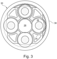
- the epicyclic planetary gear box 30 is shown by way of example in greater detail in FIG. 3 .
- the sun gear 28, planet gears 32 and ring gear 38 in each case comprise teeth on their periphery to allow intermeshing with the other gearwheels. However, for clarity, only exemplary portions of the teeth are illustrated in FIG. 3 .
- four planet gears 32 are illustrated, it will be apparent to a person skilled in the art that more or fewer planet gears 32 can be provided within the scope of protection of the claimed invention.
- Practical applications of an epicyclic planetary gear box 30 generally comprise at least three planet gears 32.
- any suitable arrangement of the bearings between rotating and stationary parts of the gas turbine engine 10 may be used, and the invention is not limited to the exemplary arrangement of FIG. 2 .
- the gear box 30 has a star arrangement (described above)
- the arrangement of output and supporting linkages and bearing positions would usually be different than that shown by way of example in FIG. 2 .
- the present invention extends to a gas turbine engine having any arrangement of types of gear box (for example star or epicyclic-planetary), supporting structures, input and output shaft arrangement, and bearing locations.
- gear box for example star or epicyclic-planetary
- supporting structures for example star or epicyclic-planetary
- input and output shaft arrangement for example star or epicyclic-planetary
- bearing locations for example star or epicyclic-planetary
- the invention may be applied, for example, to any type of gas turbine engine, such as e.g. an open-rotor engine (in which the fan stage is not surrounded by an engine nacelle) or a turboprop engine.
- the gas turbine engine 10 may not comprise a gear box 30.
- the shaft component 50 can also comprise e.g. conical parts or flanges. At the ends of the shaft components 50 (not shown here), metallic end fittings can be positioned. The attachment of the end fittings can be effected by adhesive and/or mechanical means.
- the shaft coupling can be e.g. a spline or a curvic coupling.
- the shaft component 50 has uniform fiber properties but for two regions 51, 52 distributed along the axis. As shown in the context of Fig. 6 , more than two regions 51, 52, 53 are also possible, giving a wide range of design choices for optimizations.
- the regions 51, 52, 53 can differ e.g. in the orientation of the fibers 60 resulting in differences in the behavior.
- different fibers 60 could be used.
- Different geometric properties e.g. fiber diameters, fiber lengths
- the regions 51, 52 can also be positioned radially.
- the radially outer region 51 has fibers 60 oriented axially; the radially inner region 52 has fibers 60 in circumferential orientation. Obviously, there could be more than two regions 51, 52 arranged radially.
- FIG. 6 an embodiment of a shaft component 50 with two adjacent regions 51, 52 is shown, each region having different orientations of the fibers 60.
- the fibers 60 are wound under 45°/-45°
- the fibers 60 are wound under 90° to the rotational axis 9 of the shaft component 50.
- FIG. 9A a generally known shaft design is shown schematically.
- the left end of the shaft component 50 is linked to the sun gear 26, the right end of the shaft component is linked to a driving part, such as a turbine section (not shown here).
- the shaft component 50 comprises three undulant sections 71, 72, 73 with the aim of deliberately altering the stiffness of the shaft component 50.
- the centerline is relatively straight till the first undulant section 71 as the shaft component is relatively stiff.
- the first and second undulant sections 71, 72 reduce the stiffness locally, so that the center line comprises two slightly curved sections in the respective undulant sections.
- the third undulant section 73 introduces a further localized reduction of the stiffness, causing a further curved section in the center line.
- regions designated C-E have low or very low axial stiffness properties, they only contribute to the overall stiffness of the shaft in proportion to their length, allowing the design to meet the overall target axial stiffness.
- the central region 53 designated A-C or B-C maintains the natural frequency at a high value and avoids any damaging whirling vibrations.
- the two regions 51, 52 designated C-E both deform in a pivoting style motion to allow any mis-mismatch between the ends of the shaft component 50 while isolating the gearbox from damaging bending moments.
- the axial and torsional stiffness' can be maintained while producing significant reductions in the bending moment shaft stiffness, without the need to include reductions in stiffness with large geometric features as shown in regions 51, 52.
- the composite shaft can actually have a plain crosssection without any significant disturbance.
Applications Claiming Priority (1)
| Application Number | Priority Date | Filing Date | Title |
|---|---|---|---|
| GBGB2111881.5A GB202111881D0 (en) | 2021-08-19 | 2021-08-19 | Shaft component and method for producing a shaft component |
Publications (1)
| Publication Number | Publication Date |
|---|---|
| EP4137692A1 true EP4137692A1 (fr) | 2023-02-22 |
Family
ID=77913976
Family Applications (1)
| Application Number | Title | Priority Date | Filing Date |
|---|---|---|---|
| EP22187797.0A Pending EP4137692A1 (fr) | 2021-08-19 | 2022-07-29 | Composant d'arbre et procédé de fabrication d'un composant d'arbre |
Country Status (3)
| Country | Link |
|---|---|
| US (1) | US11840964B2 (fr) |
| EP (1) | EP4137692A1 (fr) |
| GB (1) | GB202111881D0 (fr) |
Citations (5)
| Publication number | Priority date | Publication date | Assignee | Title |
|---|---|---|---|---|
| US4248062A (en) * | 1979-10-05 | 1981-02-03 | Shakespeare Company | Drive shaft assembly and method for making same |
| US20090038435A1 (en) | 2007-08-08 | 2009-02-12 | Lunin Stepan V | Split torque geared power transmissions with composite output shafts |
| US20160230805A1 (en) * | 2015-02-09 | 2016-08-11 | Rolls-Royce Deutschland Ltd & Co Kg | Shaft of a gas turbine engine in hybrid design |
| US20200165981A1 (en) | 2018-11-27 | 2020-05-28 | Rolls-Royce Deutschland Ltd & Co Kg | Shaft component and method for producing a shaft component |
| US20200166005A1 (en) * | 2018-11-27 | 2020-05-28 | Rolls-Royce Deutschland Ltd & Co Kg | Drive shaft component and method of producing the drive shaft component |
Family Cites Families (22)
| Publication number | Priority date | Publication date | Assignee | Title |
|---|---|---|---|---|
| US3651661A (en) | 1970-02-02 | 1972-03-28 | United Aircraft Corp | Composite shaft with integral end flange |
| DE2909393A1 (de) | 1979-03-09 | 1981-03-12 | M.A.N. Maschinenfabrik Augsburg-Nürnberg AG, 8000 München | Zylindrischer hohlkoerper aus faserverbundwerkstoff |
| JPH0640904B2 (ja) * | 1985-05-27 | 1994-06-01 | 住友ゴム工業株式会社 | ゴルフクラブセット |
| US4863416A (en) | 1985-08-16 | 1989-09-05 | Lord Corporation | Misalignment accommodating composite shaft |
| JPH07102236B2 (ja) * | 1990-02-16 | 1995-11-08 | ソマール株式会社 | ゴルフクラブシャフト及びその製造方法 |
| US5556677A (en) * | 1994-01-07 | 1996-09-17 | Composite Development Corporation | Composite shaft structure and manufacture |
| DE19538360C1 (de) * | 1995-10-14 | 1997-04-03 | Dornier Gmbh | Kardanwelle für Kraftfahrzeuge |
| JPH09267400A (ja) * | 1996-04-02 | 1997-10-14 | Toray Ind Inc | Frp曲り管 |
| JPH09300497A (ja) * | 1996-05-16 | 1997-11-25 | Toray Ind Inc | 繊維強化プラスチック製大型柱状体 |
| DE202004005380U1 (de) * | 2004-04-01 | 2004-06-09 | Hackforth Gmbh | Sektionierte Welle aus Faserverbundwerkstoff |
| FR2873952B1 (fr) * | 2004-08-06 | 2008-07-04 | Fibres Et Carbone Sa Soc D | Elements allonges renforces tels que tubes, procede et appareil de fabrication |
| NZ561410A (en) * | 2007-09-11 | 2010-04-30 | Parker Hannifin Gmbh | End-fittings for composite tubes, method for joining fittings to the ends of composite tubes and composite tubes incorporating end-fittings |
| DE102008056018A1 (de) | 2008-11-05 | 2010-05-06 | Rolls-Royce Deutschland Ltd & Co Kg | Triebwerkswelle für ein Gasturbinentriebwerk |
| US20120283029A1 (en) * | 2009-12-29 | 2012-11-08 | Lawrie Duncan J | High torque density flexible composite driveshaft |
| DE102010048926A1 (de) * | 2010-10-19 | 2012-04-19 | Rolls-Royce Deutschland Ltd & Co Kg | Antriebswelle, insbesondere Radialwelle für ein Gasturbinentriebwerk |
| DE102010048717B4 (de) * | 2010-10-19 | 2015-08-06 | Cg Tec Gmbh | Biegsame Hybridwelle zur Übertragung von Drehmomenten |
| DE102012022198A1 (de) | 2012-11-13 | 2014-05-28 | Rolls-Royce Deutschland Ltd & Co Kg | Welle eines Gasturbinentriebwerks, insbesondere einer Radialwelle oder einer zur Maschinenachse in einem Winkel angeordneten Welle |
| EP2985132A1 (fr) * | 2012-12-13 | 2016-02-17 | Enrichment Technology Company Ltd. Zweigniederlassung Deutschland | Renforcement intégré à la structure dans des composants enroulés à base de matières composites |
| DE102016122574A1 (de) * | 2016-11-23 | 2018-05-24 | Dr. Ing. H.C. F. Porsche Aktiengesellschaft | Übertragungswelle für die Übertragung von Rotationsbewegungen in einem Fahrzeug |
| US20210156415A1 (en) * | 2019-11-25 | 2021-05-27 | Bell Textron Inc. | Layup of tail rotor drive shaft tubes |
| CN112793670B (zh) * | 2021-01-21 | 2023-01-10 | 宁波吉利汽车研究开发有限公司 | 一种加强管及加强管的制造方法 |
| CN114483759A (zh) * | 2021-12-24 | 2022-05-13 | 上海华渔新材料科技有限公司 | 一种高扭转强度缠绕成型复合材料传动轴及其制备方法 |
-
2021
- 2021-08-19 GB GBGB2111881.5A patent/GB202111881D0/en not_active Ceased
-
2022
- 2022-07-29 EP EP22187797.0A patent/EP4137692A1/fr active Pending
- 2022-08-04 US US17/881,225 patent/US11840964B2/en active Active
Patent Citations (5)
| Publication number | Priority date | Publication date | Assignee | Title |
|---|---|---|---|---|
| US4248062A (en) * | 1979-10-05 | 1981-02-03 | Shakespeare Company | Drive shaft assembly and method for making same |
| US20090038435A1 (en) | 2007-08-08 | 2009-02-12 | Lunin Stepan V | Split torque geared power transmissions with composite output shafts |
| US20160230805A1 (en) * | 2015-02-09 | 2016-08-11 | Rolls-Royce Deutschland Ltd & Co Kg | Shaft of a gas turbine engine in hybrid design |
| US20200165981A1 (en) | 2018-11-27 | 2020-05-28 | Rolls-Royce Deutschland Ltd & Co Kg | Shaft component and method for producing a shaft component |
| US20200166005A1 (en) * | 2018-11-27 | 2020-05-28 | Rolls-Royce Deutschland Ltd & Co Kg | Drive shaft component and method of producing the drive shaft component |
Also Published As
| Publication number | Publication date |
|---|---|
| GB202111881D0 (en) | 2021-10-06 |
| US11840964B2 (en) | 2023-12-12 |
| US20230054031A1 (en) | 2023-02-23 |
Similar Documents
| Publication | Publication Date | Title |
|---|---|---|
| US11415008B2 (en) | Vane | |
| US20200166005A1 (en) | Drive shaft component and method of producing the drive shaft component | |
| US20200165981A1 (en) | Shaft component and method for producing a shaft component | |
| US11143112B2 (en) | High power epicyclic gearbox and operation thereof | |
| US11268452B2 (en) | High power epicyclic gearbox and operation thereof | |
| EP3587772A1 (fr) | Turbine à gaz | |
| US20220090541A1 (en) | Reliable gearbox for gas turbine engine | |
| EP2959131B1 (fr) | Structure d'attachement composite à armure 3d | |
| EP3839211A1 (fr) | Moteur à turbine à gaz avec paliers d'arbre | |
| US11840965B2 (en) | Aircraft engine | |
| CN112923024A (zh) | 用于气体涡轮引擎的可靠齿轮箱 | |
| EP3865667B1 (fr) | Aube de stator variable et procédé de fabrication d'aube de stator variable | |
| US20240117769A1 (en) | Midshaft rating for turbomachine engines | |
| US20210172508A1 (en) | High power epicyclic gearbox and operation thereof | |
| CN112918686A (zh) | 高功率周转齿轮箱及其操作 | |
| EP4137692A1 (fr) | Composant d'arbre et procédé de fabrication d'un composant d'arbre | |
| US20200165938A1 (en) | Gear box casing and method for producing a gear box casing | |
| EP4299882A1 (fr) | Support de support de palier à longueur axiale réduite | |
| US20230193770A1 (en) | Part of a gas turbine engine and method for the manufacturing the part | |
| EP3712409A1 (fr) | Support pour moteur de turbine à gaz | |
| CN112923021A (zh) | 飞行器引擎 | |
| CN112922741A (zh) | 飞行器引擎 | |
| CA3065582A1 (fr) | Turbine a gaz |
Legal Events
| Date | Code | Title | Description |
|---|---|---|---|
| PUAI | Public reference made under article 153(3) epc to a published international application that has entered the european phase |
Free format text: ORIGINAL CODE: 0009012 |
|
| STAA | Information on the status of an ep patent application or granted ep patent |
Free format text: STATUS: THE APPLICATION HAS BEEN PUBLISHED |
|
| AK | Designated contracting states |
Kind code of ref document: A1 Designated state(s): AL AT BE BG CH CY CZ DE DK EE ES FI FR GB GR HR HU IE IS IT LI LT LU LV MC MK MT NL NO PL PT RO RS SE SI SK SM TR |
|
| STAA | Information on the status of an ep patent application or granted ep patent |
Free format text: STATUS: REQUEST FOR EXAMINATION WAS MADE |
|
| 17P | Request for examination filed |
Effective date: 20230414 |
|
| RBV | Designated contracting states (corrected) |
Designated state(s): AL AT BE BG CH CY CZ DE DK EE ES FI FR GB GR HR HU IE IS IT LI LT LU LV MC MK MT NL NO PL PT RO RS SE SI SK SM TR |
|
| STAA | Information on the status of an ep patent application or granted ep patent |
Free format text: STATUS: EXAMINATION IS IN PROGRESS |
|
| 17Q | First examination report despatched |
Effective date: 20240227 |