EP4137655A1 - Putty knife - Google Patents
Putty knife Download PDFInfo
- Publication number
- EP4137655A1 EP4137655A1 EP22460036.1A EP22460036A EP4137655A1 EP 4137655 A1 EP4137655 A1 EP 4137655A1 EP 22460036 A EP22460036 A EP 22460036A EP 4137655 A1 EP4137655 A1 EP 4137655A1
- Authority
- EP
- European Patent Office
- Prior art keywords
- blade
- connector
- handle
- support
- putty knife
- Prior art date
- Legal status (The legal status is an assumption and is not a legal conclusion. Google has not performed a legal analysis and makes no representation as to the accuracy of the status listed.)
- Granted
Links
- 230000000295 complement effect Effects 0.000 claims abstract description 6
- 239000002184 metal Substances 0.000 claims abstract description 5
- 230000037431 insertion Effects 0.000 claims abstract 2
- 238000003780 insertion Methods 0.000 claims abstract 2
- 238000010276 construction Methods 0.000 description 12
- 238000009499 grossing Methods 0.000 description 5
- 238000000576 coating method Methods 0.000 description 3
- 239000000463 material Substances 0.000 description 3
- 239000011248 coating agent Substances 0.000 description 2
- 229920001169 thermoplastic Polymers 0.000 description 2
- 239000004743 Polypropylene Substances 0.000 description 1
- 229910000831 Steel Inorganic materials 0.000 description 1
- 239000004433 Thermoplastic polyurethane Substances 0.000 description 1
- 230000006978 adaptation Effects 0.000 description 1
- 238000004140 cleaning Methods 0.000 description 1
- 230000008878 coupling Effects 0.000 description 1
- 238000010168 coupling process Methods 0.000 description 1
- 238000005859 coupling reaction Methods 0.000 description 1
- 230000003247 decreasing effect Effects 0.000 description 1
- 230000000694 effects Effects 0.000 description 1
- 239000000945 filler Substances 0.000 description 1
- 229920001903 high density polyethylene Polymers 0.000 description 1
- 239000004700 high-density polyethylene Substances 0.000 description 1
- 239000004033 plastic Substances 0.000 description 1
- 229920003023 plastic Polymers 0.000 description 1
- 229920000642 polymer Polymers 0.000 description 1
- -1 polypropylene Polymers 0.000 description 1
- 229920001155 polypropylene Polymers 0.000 description 1
- 239000004800 polyvinyl chloride Substances 0.000 description 1
- 229920000915 polyvinyl chloride Polymers 0.000 description 1
- 230000003014 reinforcing effect Effects 0.000 description 1
- 238000009877 rendering Methods 0.000 description 1
- 230000006641 stabilisation Effects 0.000 description 1
- 239000010959 steel Substances 0.000 description 1
- 229920002397 thermoplastic olefin Polymers 0.000 description 1
- 229920002803 thermoplastic polyurethane Polymers 0.000 description 1
- 239000002966 varnish Substances 0.000 description 1
Images
Classifications
-
- E—FIXED CONSTRUCTIONS
- E04—BUILDING
- E04F—FINISHING WORK ON BUILDINGS, e.g. STAIRS, FLOORS
- E04F21/00—Implements for finishing work on buildings
- E04F21/28—Implements for finishing work on buildings for glazing
- E04F21/32—Putty knives; Putty removers
-
- B—PERFORMING OPERATIONS; TRANSPORTING
- B25—HAND TOOLS; PORTABLE POWER-DRIVEN TOOLS; MANIPULATORS
- B25G—HANDLES FOR HAND IMPLEMENTS
- B25G1/00—Handle constructions
- B25G1/06—Handle constructions reversible or adjustable for position
-
- B—PERFORMING OPERATIONS; TRANSPORTING
- B25—HAND TOOLS; PORTABLE POWER-DRIVEN TOOLS; MANIPULATORS
- B25G—HANDLES FOR HAND IMPLEMENTS
- B25G3/00—Attaching handles to the implements
- B25G3/02—Socket, tang, or like fixings
- B25G3/12—Locking and securing devices
- B25G3/26—Locking and securing devices comprising nails, screws, bolts, or pins traversing or entering the socket
-
- B—PERFORMING OPERATIONS; TRANSPORTING
- B25—HAND TOOLS; PORTABLE POWER-DRIVEN TOOLS; MANIPULATORS
- B25G—HANDLES FOR HAND IMPLEMENTS
- B25G3/00—Attaching handles to the implements
- B25G3/38—Hinged, pivoted, swivelling, or folding joints
-
- E—FIXED CONSTRUCTIONS
- E04—BUILDING
- E04F—FINISHING WORK ON BUILDINGS, e.g. STAIRS, FLOORS
- E04F21/00—Implements for finishing work on buildings
- E04F21/165—Implements for finishing work on buildings for finishing joints, e.g. implements for raking or filling joints, jointers
Definitions
- the subject of the invention is a putty knife intended for use in construction works, such as filling and smoothing of missing wall materials, initial surface levelling or surface cleaning by coating removal. Putty knives are also used in finishing works, mainly at the stage of the final application, modelling and final surface levelling.
- a solution described in FR2969192B1 is known in the field, which discloses a blade for coating and application, with a catching unit containing a support forming the working part together with the first side and the second side, wherein the sides are tilted at an angle determined by the user.
- the blade is removable and foldable, such that it forms the first side and the second side, which is tilted at an angle set by the user, similar to the angle of the supporting part.
- the first side of the catching unit is placed on the outer side of the product applying blade.
- the second side of the catching unit fixes the second side of the blade.
- the second side of the blade is used to apply the product.
- a tool including an elongated smoothing element intended for spreading and smoothing of render and a support, to which the elongated smoothing element is attached.
- the support includes a part intended for affixing a holder including two chucks intended for clamping the affixing part.
- the chuck is provided with functional elements intended for moving the chuck, once attached. These elements adapted to connecting or moving the chucks remotely, while the affixing part has a circular cross-section in a plane virtually perpendicular to the length of the blade.
- the next known solution comes from the European patent EP2471608 , which discloses a putty knife with a rear part for fixing a handle, a blade handle and a blade, wherein the blade is made of a thermoplastic polymer with hardness between 45 and 75 degrees in the Shore scale.
- the thermoplastic polymer is selected from thermoplastic polyurethanes and thermoplastic olefin polymers.
- Rigid plastics include high-density polyethylene, polypropylene or PVC.
- Two sides of the blade are smooth surfaces used to smooth varnish coatings.
- the objective of the invention is to provide an economic model of a construction putty knife, the working elements of which, subject to natural wear and tear, may be fully replaced and their design includes as small number of elements as possible.
- the main design element according to the invention is a blade with an assembly profile.
- the design of the putty knife according to the invention is intended to be disassembled to the maximum possible degree.
- the ability to remove individual design elements was ensured by the use of an assembly kit in the form of a bolt with a butterfly nut, with the kit directly cooperating with openings provided in the main elements of the putty knife design. This design solves the main problem with previously known solutions - mitigates the issue of spare parts unavailability to the minimum degree.
- the construction putty knife Includes a metal blade and a handle placed inside a connector, wherein the connector is an angle-adjusted, removable connection between the handle and the fixing profile, in which the working blade is placed.
- the construction putty knife is characterised in that the connector includes a support, which is flat in the connection area with the flat profile fixing the blade, where the support is connected to the blade fixing profile, using connectors.
- the connector is provided with a socket with an opening for the element connecting the connector with the handle.
- the handle is provided at the end with a socket cooperating with the connector socket using a connecting element.
- Sockets are provided with complementary, radial protrusions at cooperating contact surfaces of these sockets.
- the radial protrusions at the socket contact surfaces preferably have triangular cross-section.
- the putty knife support is preferably provided with stiffening elements in the form of ribs.
- the putty knife support preferably has an aperture intended to introduce the fixing profile.
- the construction putty knife is provided with connecting elements, preferably bolts with butterfly nuts.
- the blade fixing profile and the connector are preferably provided with at least two cooperating openings.
- the putty knife according to the invention is a flexible construction tool.
- the blade namely the part subject to natural wear and tear, is removable and can be fully replaced.
- a blade with a specific length may be replaced with a longer or a shorter blade, as necessary.
- the other part of the putty knife comprising an adjustable connector and a handle is a reusable tool, with the option of replacing only the used blade is provided.
- the universal sizes as well as the ability to adjust the angle at which the putty knife handle is set against the connector with a fixed blade, allows adjustment of the angle o incidence of the putty knife against the wall, onto which the filler coat is applied using the putty knife.
- the putty knife modules include a set of permanently connected elements, such as the blade and the handle, for which the connector with the handle is an additional accessory.
- the use of the construction putty knife according to the invention also allows the blade itself to be executed as a replaceable element, wherein it is a consumable part requiring less material than the entire putty knife.
- the replacement cost of the blade itself is significantly lower than the purchase of the complete putty knife, in which various connectors were an additional, functional accessory.
- the metal blade and the assembly kit made of metal make the design eco-friendly, as a product fully recyclable after blade replacement.
- the design of the putty knife according to the invention additionally enables the use of a varied length handle with the option of changing the angle of incidence against the rendered surface by loosening the connecting screw, rotation on the radial protrusions of the sockets and connecting the sockets together again with the blade in the new position.
- Fig. 1 and Fig. 2 present the connector 4, comprising an element connecting the blade 2 shown in Fig. 3 and Fig. 4 with the handle 3, the end part of which is shown in Fig. 8 to Fig. 12 .
- These Figures show only the part of the handle 3 cooperating with the connector 4 because of the fact that one of the tasks of the invention is to use the handle 3 with a significant length, enabling the use of the putty knife at higher parts of walls of a building without the use of a ladder.
- the Figures show only the part of the handle 3 cooperating with the connector 4 in order to clearly present the unit connecting the connector 4 with the handle 3.
- the work of a putty knife at various heights using the handle 3, the length of which may be variable or which may be held by the operator at various levels, within a wide range of heights, requires the blade 2 of the putty knife to be always set at the same or a similar angle against the wall in order to achieve the required quality of the render.
- the angle at which the connector 4 with the fixing profile 5 fixing the blade 2 placed on it against the handle 3 must be different, according to the length of this handle 3 or to the level at which it is held by the operator.
- a system of cooperating sockets 9.1 and 9.2 is provided in the solution according to the invention, at the point of connection between the handle 3 and the connector 4.
- Sockets 9.1 and 9.2 are provided on cooperating surfaces with complementary, radial protrusions 12 shown in Fig. 1, Fig. 2 , Fig. 8 and Fig. 10 to Fig. 12 .
- Fig. 3 and Fig. 4 show the blade 2 of a construction putty knife fixed permanently inside the fixing profile 5.
- the blade 2 is usually made of flexible steel sheet enabling adaptation of the edge spreading the rendering mass on the wall in order to achieve a smooth effect.
- the blade 2 is provided with openings 14 in the fixing profile 5, as shown in Fig. 4 , in order to facilitate blade attachment in the manual handle, not shown in these Figures, or to the (not shown in the Figures) support 6 of the connector 4. Openings 14 in the fixing profile 5 cooperate with openings 14 in the support plate 6, shown in Fig. 1 and Fig. 2 .
- attachment involves screwing the fixing profile 5 with the blade 2 to the support 6 of the connector 4 using connecting elements 8 in the form of bolts with butterfly nuts. This is shown in Fig. 5 and Fig. 6 , as well as in Fig. 7 , in a view towards the bottom surface of the blade 2.
- the support 6 is shown in the attached Fig. 1 and Fig. 2 , in two embodiments. In both embodiments, it comprises a flat element, to which the blade 2 fixed permanently in the fixing profile 5 is attached, as shown in Fig. 3 and Fig. 4 . Openings 14 are made in the support 6, corresponding to openings 14 in the fixing profile 5 shown in Fig. 4 .
- This flat element provided as support 6 is provided with stiffening ribs 7 shown in Fig. 1, Fig. 2 and Fig. 5 .
- the replaced support 6 is made of a different material, not shown in the attached figure, it may not require the use of ribs 7.
- the support plate 6 is provided outside the ribs 7 with a circumferential stiffening 16 of two side edges, as well as of the rear edge, to which the socket 9.1 of the connector 4 is attached.
- Fig. 1 and Fig. 2 show two different embodiments of the support 6.
- the embodiment of the support 6 in Fig. 1 is characterised in that the support panel 6 is provided with an aperture 13, into which the fixing profile 5 with the blade 2 is placed between placement inside the openings 14 of the connecting elements 8 provided as bolts with butterfly nuts, connecting the blade 2 with the connector 4.
- the plate of the support 6 is not provided with an aperture 13 and in this embodiment of the construction putty knife 1, with the fixing profile 5 with the blade 2 screwed on to the plate of the support 6 through the openings 14, from the bottom side, using the aforementioned bolts.
- the removable connections of the construction putty knife 1 use connectors 8 and 11 in the form of bolts with butterfly nuts. This is shown in Fig. 5 .
- Such connections, with precisely tightened nuts, are stable connections, at the sme time easy to loosen in order to change the angle between the plane of the support 6 and the handle 3, followed by stabilisation of this connection by re-tightening of the connecting element 11.
- the connecting elements 8 in the form of bolts with butterfly nuts enable easy replacement of a fixing profile 5 with a blade 2 without a use of tools, with a new and identical part, or with a fixing profile 5 with a blade 2 of a different type, for example with a blade 2 with a different length, if necessary.
- Fig. 5 , Fig. 6 and Fig. 7 present a complete, assembled construction putty knife 1 according to the invention.
- These figures show connected and cooperating surfaces of the socket 9.1 of the connector 4 and of the socket 9.2 of the handle 3, according to Fig. 1 and Fig. 2 .
- the connection between surfaces 9.1 and 9.2 is particularly shown in Fig. 5 and Fig. 7.
- Fig. 6 shows that the support 6 is flat within the area of connection with the flat fixing profile 5 of the blade 2.
- FIG. 8 and Fig. 9 show the end of the handle 3 in two embodiments.
- the hand 3 has a larger diameter and the invisible here pin of the socket 9.2 is placed inside the tube comprising the handle 3.
- This solution may be used with a shorter handle 3, thus with a smaller total weight. If the handle 3 is longer than 1.5 metre, however, its total weight is excessive and its diameter has to be decreased in order to decrease the overall weight.
- This requires the use of a socket 9.2 with a clamp 15 including the handle 3 inserted inside the clamp 15. This is shown in Figs. 10 to Fig. 12 .
- the attached figures show that complementary radial protrusion 12 are provided on the cooperating surfaces of the socket 9.2 of the handle 3 and of the socket 9.1 of the connector 4. This means that once the socket 9.1 shown in Fig. 1 and the socket 9.2 shown in Fig. 9 are combined and once the connection is tightened using the connecting element 11 in the form of a screw with a butterfly nut, as shown in Fig. 5 and Fig. 6 and Fig. 7 , the radial protrusions 12 with a triangular cross-section mesh and complement one another, forming a cohesive and detachable connection.
- the connecting element 11 is passing through the openings 10 in the sockets 9.1 and 9.2.
- connection When the connecting element 11 is loosened, the connection can be disconnected and the handle 3 may be rotated around the connector 4 in order to achieve a different angle between the handle 3 and the blade 2 attached to the support 6.
- the connection of both those elements is then fixed at the adjusted angle, by pressing both sockets 9.1 and 9.2 together using the connecting element 11 in the form of the aforementioned screw with a butterfly nut, passing through openings 10 in the sockets 9.1 and 9.2.
Landscapes
- Engineering & Computer Science (AREA)
- Architecture (AREA)
- Mechanical Engineering (AREA)
- Civil Engineering (AREA)
- Structural Engineering (AREA)
- Knives (AREA)
- Coating Apparatus (AREA)
- Working Measures On Existing Buildindgs (AREA)
Abstract
Description
- The subject of the invention is a putty knife intended for use in construction works, such as filling and smoothing of missing wall materials, initial surface levelling or surface cleaning by coating removal. Putty knives are also used in finishing works, mainly at the stage of the final application, modelling and final surface levelling.
- A solution described in
FR2969192B1 - Another solution is known from the
FR3020389 - Another solution is known from the international application
WO0032893 - The next known solution comes from the European patent
EP2471608 , which discloses a putty knife with a rear part for fixing a handle, a blade handle and a blade, wherein the blade is made of a thermoplastic polymer with hardness between 45 and 75 degrees in the Shore scale. The thermoplastic polymer is selected from thermoplastic polyurethanes and thermoplastic olefin polymers. Rigid plastics include high-density polyethylene, polypropylene or PVC. Two sides of the blade are smooth surfaces used to smooth varnish coatings. - The objective of the invention is to provide an economic model of a construction putty knife, the working elements of which, subject to natural wear and tear, may be fully replaced and their design includes as small number of elements as possible. The main design element according to the invention is a blade with an assembly profile. The design of the putty knife according to the invention is intended to be disassembled to the maximum possible degree. The ability to remove individual design elements was ensured by the use of an assembly kit in the form of a bolt with a butterfly nut, with the kit directly cooperating with openings provided in the main elements of the putty knife design. This design solves the main problem with previously known solutions - mitigates the issue of spare parts unavailability to the minimum degree.
- According to the invention, the construction putty knife. Includes a metal blade and a handle placed inside a connector, wherein the connector is an angle-adjusted, removable connection between the handle and the fixing profile, in which the working blade is placed.
- According to the invention, the construction putty knife is characterised in that the connector includes a support, which is flat in the connection area with the flat profile fixing the blade, where the support is connected to the blade fixing profile, using connectors. The connector is provided with a socket with an opening for the element connecting the connector with the handle. The handle is provided at the end with a socket cooperating with the connector socket using a connecting element. Sockets are provided with complementary, radial protrusions at cooperating contact surfaces of these sockets.
- According to the invention, the radial protrusions at the socket contact surfaces preferably have triangular cross-section.
- According to the invention, the putty knife support is preferably provided with stiffening elements in the form of ribs.
- According to the invention, the putty knife support preferably has an aperture intended to introduce the fixing profile.
- According to the invention, the construction putty knife is provided with connecting elements, preferably bolts with butterfly nuts.
- According to the invention, the blade fixing profile and the connector are preferably provided with at least two cooperating openings.
- Thanks to the use of universal sizes of the assembly openings and the elements of the assembly kit, the putty knife according to the invention is a flexible construction tool. The blade, namely the part subject to natural wear and tear, is removable and can be fully replaced. A blade with a specific length may be replaced with a longer or a shorter blade, as necessary. The other part of the putty knife comprising an adjustable connector and a handle is a reusable tool, with the option of replacing only the used blade is provided. The universal sizes as well as the ability to adjust the angle at which the putty knife handle is set against the connector with a fixed blade, allows adjustment of the angle o incidence of the putty knife against the wall, onto which the filler coat is applied using the putty knife. This enables the use of a long putty knife handle for application of the coat at high parts of the walls, which require adjustment of the angle between the handle and the putty knife blade plane in order to achieve the correct angle of incidence of the putty knife blade against the wall. In the previously known solutions, the putty knife modules include a set of permanently connected elements, such as the blade and the handle, for which the connector with the handle is an additional accessory.
- The use of the construction putty knife according to the invention also allows the blade itself to be executed as a replaceable element, wherein it is a consumable part requiring less material than the entire putty knife. The replacement cost of the blade itself is significantly lower than the purchase of the complete putty knife, in which various connectors were an additional, functional accessory. In addition, the metal blade and the assembly kit made of metal make the design eco-friendly, as a product fully recyclable after blade replacement.
- The design of the putty knife according to the invention additionally enables the use of a varied length handle with the option of changing the angle of incidence against the rendered surface by loosening the connecting screw, rotation on the radial protrusions of the sockets and connecting the sockets together again with the blade in the new position.
- The object of the invention is presented in an embodiment in the attached drawing, in which individual figures of the drawing represent as follows:
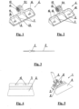
- Fig. 1 -
- a connector including a support with the assembly aperture, the head and reinforcing ribs,
- Fig. 2 -
- a connector according to
Fig. 1 in a different embodiment, - Fig. 3 -
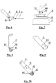
- a blade with a fixing profile, in a side view, according to the blade plane,
- Fig. 4 -
- a blade with a fixing profile, in a top view,
- Fig. 5 -
- the construction putty knife in an axonometric view,
- Fig. 6 -
- a complete putty knife, in a side view,
- Fig. 7 -
- a putty knife in a bottom view,
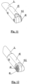
- Fig. 8 -
- the head placed inside the handle, when looked towards the radial protrusions,
- Fig. 9 -
- the head placed inside the handle, in an axonometric view,
- Fig. 10 -
- the head placed outside the handle, when looked towards the radial protrusions,
- Fig. 11 -
- the head according to
Fig. 10 viewed from the other side, - Fig. 12
- -the head placed on the putty knife handle, in an axonometric view.
-
Fig. 1 and Fig. 2 present the connector 4, comprising an element connecting theblade 2 shown inFig. 3 and Fig. 4 with thehandle 3, the end part of which is shown inFig. 8 to Fig. 12 . These Figures show only the part of thehandle 3 cooperating with the connector 4 because of the fact that one of the tasks of the invention is to use thehandle 3 with a significant length, enabling the use of the putty knife at higher parts of walls of a building without the use of a ladder. Thus, the Figures show only the part of thehandle 3 cooperating with the connector 4 in order to clearly present the unit connecting the connector 4 with thehandle 3. - The work of a putty knife at various heights using the
handle 3, the length of which may be variable or which may be held by the operator at various levels, within a wide range of heights, requires theblade 2 of the putty knife to be always set at the same or a similar angle against the wall in order to achieve the required quality of the render. Thus, when working on different heights, the angle at which the connector 4 with the fixingprofile 5 fixing theblade 2 placed on it against thehandle 3 must be different, according to the length of thishandle 3 or to the level at which it is held by the operator. - Thus, a system of cooperating sockets 9.1 and 9.2 is provided in the solution according to the invention, at the point of connection between the
handle 3 and the connector 4. Sockets 9.1 and 9.2 are provided on cooperating surfaces with complementary,radial protrusions 12 shown inFig. 1, Fig. 2 ,Fig. 8 and Fig. 10 toFig. 12 . Once the connectingelement 11 in the form of a bolt with a butterfly nut is loosened, theprotrusions 12 enable to change the angle between thehandle 3 and the connector 4, and finally, between the plane of theblade 2 and the wall, and after tightening this connectingelement 11, they enable restoration of a stable connection between these two elements 9.1, 9.2, but at a different angle, -
Fig. 3 and Fig. 4 show theblade 2 of a construction putty knife fixed permanently inside the fixingprofile 5. Theblade 2 is usually made of flexible steel sheet enabling adaptation of the edge spreading the rendering mass on the wall in order to achieve a smooth effect. Theblade 2 is provided withopenings 14 in the fixingprofile 5, as shown inFig. 4 , in order to facilitate blade attachment in the manual handle, not shown in these Figures, or to the (not shown in the Figures)support 6 of the connector 4.Openings 14 in the fixingprofile 5 cooperate withopenings 14 in thesupport plate 6, shown inFig. 1 and Fig. 2 . In this embodiment, attachment involves screwing the fixingprofile 5 with theblade 2 to thesupport 6 of the connector 4 using connectingelements 8 in the form of bolts with butterfly nuts. This is shown inFig. 5 andFig. 6 , as well as inFig. 7 , in a view towards the bottom surface of theblade 2. - The
support 6 is shown in the attachedFig. 1 and Fig. 2 , in two embodiments. In both embodiments, it comprises a flat element, to which theblade 2 fixed permanently in the fixingprofile 5 is attached, as shown inFig. 3 and Fig. 4 .Openings 14 are made in thesupport 6, corresponding toopenings 14 in the fixingprofile 5 shown inFig. 4 . This flat element provided assupport 6 is provided with stiffeningribs 7 shown inFig. 1, Fig. 2 and Fig. 5 . In other example embodiments, if the replacedsupport 6 is made of a different material, not shown in the attached figure, it may not require the use ofribs 7. In the described embodiment, thesupport plate 6 is provided outside theribs 7 with a circumferential stiffening 16 of two side edges, as well as of the rear edge, to which the socket 9.1 of the connector 4 is attached. -
Fig. 1 and Fig. 2 show two different embodiments of thesupport 6. The embodiment of thesupport 6 inFig. 1 is characterised in that thesupport panel 6 is provided with anaperture 13, into which thefixing profile 5 with theblade 2 is placed between placement inside theopenings 14 of the connectingelements 8 provided as bolts with butterfly nuts, connecting theblade 2 with the connector 4. On the other hand, in the case of thesupport 6 presented inFig. 2 , the plate of thesupport 6 is not provided with anaperture 13 and in this embodiment of the construction putty knife 1, with the fixingprofile 5 with theblade 2 screwed on to the plate of thesupport 6 through theopenings 14, from the bottom side, using the aforementioned bolts. - The removable connections of the construction putty knife 1
use connectors Fig. 5 . Such connections, with precisely tightened nuts, are stable connections, at the sme time easy to loosen in order to change the angle between the plane of thesupport 6 and thehandle 3, followed by stabilisation of this connection by re-tightening of the connectingelement 11. On the other hand, the connectingelements 8 in the form of bolts with butterfly nuts enable easy replacement of a fixingprofile 5 with ablade 2 without a use of tools, with a new and identical part, or with a fixingprofile 5 with ablade 2 of a different type, for example with ablade 2 with a different length, if necessary. -
Fig. 5 ,Fig. 6 and Fig. 7 present a complete, assembled construction putty knife 1 according to the invention. These figures show connected and cooperating surfaces of the socket 9.1 of the connector 4 and of the socket 9.2 of thehandle 3, according toFig. 1 and Fig. 2 . The connection between surfaces 9.1 and 9.2 is particularly shown inFig. 5 andFig. 7. Fig. 6 shows that thesupport 6 is flat within the area of connection with theflat fixing profile 5 of theblade 2. - The subsequent
Figs. 8 to Fig. 12 show the end of thehandle 3 in two embodiments.Fig. 8 and Fig. 9 , thehand 3 has a larger diameter and the invisible here pin of the socket 9.2 is placed inside the tube comprising thehandle 3. This solution may be used with ashorter handle 3, thus with a smaller total weight. If thehandle 3 is longer than 1.5 metre, however, its total weight is excessive and its diameter has to be decreased in order to decrease the overall weight. This requires the use of a socket 9.2 with aclamp 15 including thehandle 3 inserted inside theclamp 15. This is shown inFigs. 10 to Fig. 12 . - The attached figures show that complementary
radial protrusion 12 are provided on the cooperating surfaces of the socket 9.2 of thehandle 3 and of the socket 9.1 of the connector 4. This means that once the socket 9.1 shown inFig. 1 and the socket 9.2 shown inFig. 9 are combined and once the connection is tightened using the connectingelement 11 in the form of a screw with a butterfly nut, as shown inFig. 5 andFig. 6 and Fig. 7 , theradial protrusions 12 with a triangular cross-section mesh and complement one another, forming a cohesive and detachable connection. The connectingelement 11 is passing through theopenings 10 in the sockets 9.1 and 9.2. When the connectingelement 11 is loosened, the connection can be disconnected and thehandle 3 may be rotated around the connector 4 in order to achieve a different angle between thehandle 3 and theblade 2 attached to thesupport 6. The connection of both those elements is then fixed at the adjusted angle, by pressing both sockets 9.1 and 9.2 together using the connectingelement 11 in the form of the aforementioned screw with a butterfly nut, passing throughopenings 10 in the sockets 9.1 and 9.2. -
- 1.
- Putty knife
- 2.
- Blade
- 3.
- Handle
- 4.
- Connector
- 5.
- Fixing profile
- 6.
- Support
- 7.
- Stiffening rib
- 8.
- Connecting element
- 9.1.
- Socket
- 9.2.
- Socket
- 10.
- Opening
- 11.
- Connecting element
- 12.
- Radial protrusion
- 13.
- Aperture
- 14.
- Opening
- 15.
- Clamp
- 16.
- Circumferential stiffening
Claims (6)
- A putty knife with a metal blade and a handle placed in a connector, wherein the connector is a detachable connection with an adjustable angle between the handle and the fixing profile, in which the working blade is placed, characterised in that the connector (4) is provided with a support (6), which is flat in the area of the connection with the flat fixing profile (5) of the blade (2), wherein the support (6) is connected with the fixing profile (5) of the blade (2), using connecting elements (8), wherein the connector (4) includes a socket (9.1) with an opening (10.1) for the fixing element (11) of the connector (4) with the handle (3), while the handle (3) is provided at the end with a socket (9.2) cooperating with the socket (9.1) of the connector (4) via a connecting element (11), wherein the sockets (9.1,9.2), are provided with complementary radial protrusions (12) on cooperating contact surfaces of those sockets (9.1,9.2).
- A putty knife according to Claim 1, characterised in that the radial protrusions (12) have triangular cross-section at the contact surfaces of the sockets (9.1,9.2).
- A putty knife according to Claim 1, characterised in that the support (6) included stiffening elements provided as ribs (7).
- A putty knife according to Claim 1, characterised in that the support (6) is provided with an aperture (13) for insertion of the fixing profile (5).
- A putty knife according to Claim 1, characterised in that the fixing elements (8,11) are provided as bolts with butterfly nuts.
- A putty knife according to Claim 1, characterised in that the fixing profile (5), the blade (2) and the connector (4) include at least two cooperating openings (14) each.
Applications Claiming Priority (1)
| Application Number | Priority Date | Filing Date | Title |
|---|---|---|---|
| PL130228U PL130228U1 (en) | 2021-08-19 | 2021-08-19 | Construction putty |
Publications (2)
| Publication Number | Publication Date |
|---|---|
| EP4137655A1 true EP4137655A1 (en) | 2023-02-22 |
| EP4137655B1 EP4137655B1 (en) | 2024-07-03 |
Family
ID=83444867
Family Applications (1)
| Application Number | Title | Priority Date | Filing Date |
|---|---|---|---|
| EP22460036.1A Active EP4137655B1 (en) | 2021-08-19 | 2022-08-11 | Putty knife |
Country Status (2)
| Country | Link |
|---|---|
| EP (1) | EP4137655B1 (en) |
| PL (1) | PL130228U1 (en) |
Citations (8)
| Publication number | Priority date | Publication date | Assignee | Title |
|---|---|---|---|---|
| JPH11198063A (en) * | 1997-10-31 | 1999-07-27 | Masaharu Tomae | Chaplet exfoliating tool |
| WO2000032893A1 (en) | 1998-12-02 | 2000-06-08 | Sciacca Phillip G | Wipe-down knife |
| US20020078518A1 (en) * | 2000-12-27 | 2002-06-27 | Zhen-Yuan Jiang | Cleaning brush structure |
| GB2456613A (en) * | 2008-01-15 | 2009-07-22 | Ashraf Hussein Elshoura | A skimming/filing/stripping knife with an adjustable head |
| EP2471608A1 (en) | 2010-12-30 | 2012-07-04 | Toupret SA | Hard-blade scraper for raking off or flattening coatings |
| FR2969192B1 (en) | 2010-12-21 | 2013-01-18 | Mondelin Roger Sas | KNIFE TO BE COATED MULTIFUNCTIONS |
| FR3020389A1 (en) | 2014-04-29 | 2015-10-30 | Marquardt | TOOL FOR COATING WITH GRIPPING AREA WITH CIRCULAR SECTION |
| CN205742917U (en) * | 2016-03-23 | 2016-11-30 | 温州市凯宇五金有限公司 | A kind of Clean-perching knife |
-
2021
- 2021-08-19 PL PL130228U patent/PL130228U1/en unknown
-
2022
- 2022-08-11 EP EP22460036.1A patent/EP4137655B1/en active Active
Patent Citations (8)
| Publication number | Priority date | Publication date | Assignee | Title |
|---|---|---|---|---|
| JPH11198063A (en) * | 1997-10-31 | 1999-07-27 | Masaharu Tomae | Chaplet exfoliating tool |
| WO2000032893A1 (en) | 1998-12-02 | 2000-06-08 | Sciacca Phillip G | Wipe-down knife |
| US20020078518A1 (en) * | 2000-12-27 | 2002-06-27 | Zhen-Yuan Jiang | Cleaning brush structure |
| GB2456613A (en) * | 2008-01-15 | 2009-07-22 | Ashraf Hussein Elshoura | A skimming/filing/stripping knife with an adjustable head |
| FR2969192B1 (en) | 2010-12-21 | 2013-01-18 | Mondelin Roger Sas | KNIFE TO BE COATED MULTIFUNCTIONS |
| EP2471608A1 (en) | 2010-12-30 | 2012-07-04 | Toupret SA | Hard-blade scraper for raking off or flattening coatings |
| FR3020389A1 (en) | 2014-04-29 | 2015-10-30 | Marquardt | TOOL FOR COATING WITH GRIPPING AREA WITH CIRCULAR SECTION |
| CN205742917U (en) * | 2016-03-23 | 2016-11-30 | 温州市凯宇五金有限公司 | A kind of Clean-perching knife |
Also Published As
| Publication number | Publication date |
|---|---|
| EP4137655B1 (en) | 2024-07-03 |
| PL130228U1 (en) | 2023-02-20 |
Similar Documents
| Publication | Publication Date | Title |
|---|---|---|
| US8321987B2 (en) | Tool system with replaceable heads and offset handle | |
| US4516868A (en) | Mastic applicator and adjustable blade assembly | |
| US20090223064A1 (en) | Tool with exchangeable piece | |
| US8904585B2 (en) | Hand-held implement for scraping and hammering | |
| US20060168753A1 (en) | Combination squeegee and hand trowel tool | |
| EP4137655A1 (en) | Putty knife | |
| US6295689B1 (en) | Wipe-down knife | |
| US7698774B1 (en) | Apparatus for producing an arcuate blade | |
| AU2015312310A1 (en) | Dual-bladed scraper with a rotatable blade-retaining head | |
| US7472447B2 (en) | Paintbrush with adjustable head | |
| US2968057A (en) | Adjustable contour knife | |
| GB2500106A (en) | A hand tool for removing exterior pipe coatings | |
| US20070006414A1 (en) | Scraper apparatus | |
| US5759590A (en) | Spackling tool | |
| US20190136550A1 (en) | Drywall repair tool | |
| US10323426B1 (en) | Wall repair plug system | |
| EP0988133B1 (en) | Grinding tool, specially for hand-held oscillating devices | |
| EP0003379A1 (en) | Tool for removing material from surfaces | |
| AU2021201273A1 (en) | Detachably attachable implement scraper | |
| US9402464B2 (en) | Paint brush adapter tool | |
| JP6457030B1 (en) | Roller applicator | |
| US11623470B2 (en) | Detachably attachable implement scraper | |
| WO2022098283A1 (en) | Scraper | |
| US619131A (en) | Chester l | |
| CN220532522U (en) | Auxiliary tool for dumping of drums |
Legal Events
| Date | Code | Title | Description |
|---|---|---|---|
| STAA | Information on the status of an ep patent application or granted ep patent |
Free format text: STATUS: UNKNOWN |
|
| PUAI | Public reference made under article 153(3) epc to a published international application that has entered the european phase |
Free format text: ORIGINAL CODE: 0009012 |
|
| STAA | Information on the status of an ep patent application or granted ep patent |
Free format text: STATUS: THE APPLICATION HAS BEEN PUBLISHED |
|
| AK | Designated contracting states |
Kind code of ref document: A1 Designated state(s): AL AT BE BG CH CY CZ DE DK EE ES FI FR GB GR HR HU IE IS IT LI LT LU LV MC MK MT NL NO PL PT RO RS SE SI SK SM TR |
|
| STAA | Information on the status of an ep patent application or granted ep patent |
Free format text: STATUS: REQUEST FOR EXAMINATION WAS MADE |
|
| 17P | Request for examination filed |
Effective date: 20230629 |
|
| RBV | Designated contracting states (corrected) |
Designated state(s): AL AT BE BG CH CY CZ DE DK EE ES FI FR GB GR HR HU IE IS IT LI LT LU LV MC MK MT NL NO PL PT RO RS SE SI SK SM TR |
|
| R17P | Request for examination filed (corrected) |
Effective date: 20230519 |
|
| GRAP | Despatch of communication of intention to grant a patent |
Free format text: ORIGINAL CODE: EPIDOSNIGR1 |
|
| STAA | Information on the status of an ep patent application or granted ep patent |
Free format text: STATUS: GRANT OF PATENT IS INTENDED |
|
| INTG | Intention to grant announced |
Effective date: 20240325 |
|
| GRAS | Grant fee paid |
Free format text: ORIGINAL CODE: EPIDOSNIGR3 |
|
| GRAA | (expected) grant |
Free format text: ORIGINAL CODE: 0009210 |
|
| STAA | Information on the status of an ep patent application or granted ep patent |
Free format text: STATUS: THE PATENT HAS BEEN GRANTED |
|
| AK | Designated contracting states |
Kind code of ref document: B1 Designated state(s): AL AT BE BG CH CY CZ DE DK EE ES FI FR GB GR HR HU IE IS IT LI LT LU LV MC MK MT NL NO PL PT RO RS SE SI SK SM TR |
|
| RIN1 | Information on inventor provided before grant (corrected) |
Inventor name: KOLESNIK-NYKIEL, PIOTR |
|
| REG | Reference to a national code |
Ref country code: CH Ref legal event code: EP |
|
| REG | Reference to a national code |
Ref country code: DE Ref legal event code: R096 Ref document number: 602022004348 Country of ref document: DE |