EP4137647B1 - Regelungsvorrichtung zur regelung des wasserverbrauchs eines unterputzspülkastens - Google Patents
Regelungsvorrichtung zur regelung des wasserverbrauchs eines unterputzspülkastens Download PDFInfo
- Publication number
- EP4137647B1 EP4137647B1 EP22156904.9A EP22156904A EP4137647B1 EP 4137647 B1 EP4137647 B1 EP 4137647B1 EP 22156904 A EP22156904 A EP 22156904A EP 4137647 B1 EP4137647 B1 EP 4137647B1
- Authority
- EP
- European Patent Office
- Prior art keywords
- snap
- water
- regulating device
- knob
- hole
- Prior art date
- Legal status (The legal status is an assumption and is not a legal conclusion. Google has not performed a legal analysis and makes no representation as to the accuracy of the status listed.)
- Active
Links
Images




Classifications
-
- E—FIXED CONSTRUCTIONS
- E03—WATER SUPPLY; SEWERAGE
- E03D—WATER-CLOSETS OR URINALS WITH FLUSHING DEVICES; FLUSHING VALVES THEREFOR
- E03D3/00—Flushing devices operated by pressure of the water supply system flushing valves not connected to the water-supply main, also if air is blown in the water seal for a quick flushing
- E03D3/12—Flushing devices discharging variable quantities of water
-
- E—FIXED CONSTRUCTIONS
- E03—WATER SUPPLY; SEWERAGE
- E03D—WATER-CLOSETS OR URINALS WITH FLUSHING DEVICES; FLUSHING VALVES THEREFOR
- E03D1/00—Water flushing devices with cisterns ; Setting up a range of flushing devices or water-closets; Combinations of several flushing devices
- E03D1/02—High-level flushing systems
- E03D1/14—Cisterns discharging variable quantities of water also cisterns with bell siphons in combination with flushing valves
-
- E—FIXED CONSTRUCTIONS
- E03—WATER SUPPLY; SEWERAGE
- E03D—WATER-CLOSETS OR URINALS WITH FLUSHING DEVICES; FLUSHING VALVES THEREFOR
- E03D1/00—Water flushing devices with cisterns ; Setting up a range of flushing devices or water-closets; Combinations of several flushing devices
- E03D1/02—High-level flushing systems
- E03D1/22—Twin or multiple flushing cisterns
-
- E—FIXED CONSTRUCTIONS
- E03—WATER SUPPLY; SEWERAGE
- E03D—WATER-CLOSETS OR URINALS WITH FLUSHING DEVICES; FLUSHING VALVES THEREFOR
- E03D2201/00—Details and methods of use for water closets and urinals not otherwise provided for
- E03D2201/30—Water injection in siphon for enhancing flushing
Definitions
- the disclosure relates to the technical field of toilet, in particular to a water consumption regulating device.
- the flushing volume of the existing toilet water tank can not be regulated.
- the flushing button is pressed, all the water in the toilet water tank will be discharged from the water outlet of the water tank at once. Although it has large flushing force, it wastes water.
- the device is a water separator installed in the water tank by plugging and pulling, which divides the water tank into two, so as to achieve the effect of reducing the capacity of water tank.
- the structure and operation of the device is particularly troublesome, and it is not convenient for the later cleaning and maintenance of the water tank.
- BAUM WILHELM DIPL PHYS DR ING discloses a two-chamber flushing box indicated that the flushing box has only one drain and filling device in one unit.
- SMITH CLARK K discloses a water saver for the water closet of a flush toilet, which allows the operator to vary the amount of water being used according to the requirements of the situation.
- a lever on the exterior of the water closet controls the egress of water from a separate secondary reservoir contained within the water closet. Varying the position of the lever varies the amount of water which escapes from a trap door on the secondary reservoir attached to the lever. When very little water is required for the flushing process the secondary reservoir remains undisturbed. However, if the entire amount of water contained within the water closet is required then the secondary reservoir will empty completely because of the position of the control lever.
- the amount of water that escapes from the secondary reservoir which varies from all to none, is determined by the position of the trap door in relation to the walls of the reservoir, which varies the effective volume of the reservoir.
- HAWKINS FRANCIS F discloses a flushing device.
- the flushing device comprising a closed tank of general arc-shaped contour; a shutter within said tank and pivoted at substantially the center of the arc thereof, so as to form a movable partition therein; and alternately operative means, including pipes opening into said tank and alternately closable by said shutter, for admitting water under pressure to said tank through one of said pipes and simultaneously' expelling water through the other of said pipes; sail shutter being so constructed with relation to said tank as to have a substantially water-tight fit therein when in either of its pipe closing positions and to permit a portion of the admitted water to pass said shutter during a part of its travel.
- KIM YOUNG SOK discloses a toilet bowl, which is provided to prevent an extreme consumption of cleaning water by easily controlling a discharging amount of cleaning water and to enhance the compatibility between the existing water tank and a partition plate, a cutoff unit and control unit.
- the toilet bowl comprises a partition plate, a cutoff unit, and a control unit.
- the partition plate is arranged inside of the central part of a water tank, thereby partitioning a washing water tank formed inside of the water tank.
- the partition plate comprises a slit.
- the cutoff unit is arranged in the partition plate so that controlling a position of the cutoff unit is possible.
- the cutoff unit gradually blocks the slit from a lower direction to an upper direction.
- the control unit controls a position of the cutoff unit.
- a water consumption regulating device is provided by the present disclosure, which has the advantages in simple structure, convenient installation and easy later repair and maintenance.
- a water consumption regulating device including a water tank, a hinged base is fixedly arranged on an inner wall of the water tank, wherein a water separator is hinged on the hinged base, and a regulating mechanism is provided between the hinged base and the water separator; the regulating mechanism is configured to drive the water separator to rotate and fix to divide accommodation space of the water tank, upper and lower parts of an side end of the water separator are respectively provided with an upper pivot and a lower pivot, an upper hinge hole and a lower hinge hole for inserting the upper pivot and the lower pivot are correspondingly arranged at upper and lower parts of the hinged base, and the water separator is correspondingly inserted into the upper hinge hole and the lower hinge hole through the upper pivot and the lower pivot.
- the regulating mechanism includes a knob
- the knob includes a knob body and an insertion portion provided at a lower end of the knob body, the upper hinge hole is arranged from top to bottom, and a lower end of the insertion portion is provided with an insertion hole; after the knob is inserted into the upper hinge hole from top to bottom through the insertion portion, the insertion hole is sleeved on a peripheral surface of the upper pivot, so that the knob is fixed relative to the upper pivot in a circumferential direction and movable relative to the upper pivot in an axial direction; a periphery of the knob body is fixedly provided with a snap portion, the hinged base is provided with an open position snap slot and a closed position snap slot, wherein the open position snap slot and the closed position snap slot are configured for receiving of the snap portion; in the open state, the snap portion is snapped in the open position snap slot; in the closed state, the water separator is driven to rotate by rotation of the knob after the knob is lifted up to separate the snap portion from the open position snap slot,
- an upper end of the knob body is provided with a accommodation hole communicated with the insertion hole, the accommodation hole is larger than a maximum diameter of the insertion hole, so that a step is formed between the accommodation hole and the insertion hole; a fixing member fixedly connected with an upper end of the upper pivot is provided in the accommodation hole, a spring located between the fixing member and the step and sleeved on an outer circumference of the upper pivot is arranged in the accommodation hole, when the snap portion of the knob is rotated to a position corresponding to the open position snap slot or the closed position snap slot, the spring drives the snap portion of the knob to snap into the open position snap slot or the closed position snap slot.
- a contact portion is provided at a bottom end and an opposite end hinged with the hinged base of the water separator, and a thickness of the contact portion is less than that of the water separator; and when in the closed state, the contact portion is against a side wall and a bottom wall of the water tank respectively.
- the upper pivot is divided from top to bottom into a sleeve portion configured to fixedly connect the fixing member and a tight fitting portion matched with the insertion hole, and a snap block is arranged opposite to an outer circumference of the sleeve portion, a lower end of the fixing member is provided with a sleeve hole, an outer circumference of the fixing member is correspondingly provided with a snap opening communicated with the sleeve hole and corresponding to the snap block, and the fixing member is correspondingly snapped into the snap block through the snap opening.
- an outer surface of the snap block is inclined outward from top to bottom.
- a notch formed by penetrating from top to bottom is arranged on a side wall of the upper hinge hole.
- a radial width of the notch is greater than a diameter of the upper pivot and less than a diameter of the upper hinge hole.
- two L-shaped fixing strips are symmetrically arranged on the inner wall of the water tank, and the two L-shaped fixing strips form a plug-in slot suitable for the hinged base.
- the water separator is made of PP.
- a cross section of the insertion hole is hexagonal
- a cross section of the upper pivot is hexagonal
- the thickness of the contact portion of the water separator is 0.1 to 0.5mm.
- the water separator divides the accommodation space into two.
- a volume of the water tank is changed from 6L to 4.5L by the regulating device.
- the water separator when the water separator is operated by the regulating mechanism to rotate against the inner wall of the water tank, the water separator divides the accommodation space into two.
- the capacity of the water tank is 6L
- the capacity of the water tank can be changed to 4.5L after being regulated by the device, so as to realize the water-saving effect.
- the structure is simple and convenient for the later repair and maintenance of the water tank.
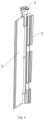
- a water consumption regulating device includes a water tank 1.
- a hinged base 2 is fixedly arranged on the inner wall of the water tank 1
- a water separator 3 is hinged on the hinged base 2
- an regulating mechanism 4 is arranged between the hinged base 2 and the water separator 3.
- the regulating mechanism 4 can drive the water separator 3 to rotate and then fix it to separate the accommodation space 10 of the water tank 1.
- the water separator 3 can divide the accommodation space 10 into two.
- the volume of the water tank 1 is 6L, and the volume of the water tank can be changed to 4.5L after being regulated by the device, so as to achieve water-saving effect.
- the present disclosure can realize the variable volume of the water tank 1 by regulating the rotation of the water separator 3 through the regulating mechanism 4.
- the structure is simple and convenient for the later repair and maintenance of the water tank 1.
- the hinge mode of the water separator 3 is as follows: the upper and lower parts of the side end of the water separator 3 are respectively provided with an upper pivot 31 and a lower pivot 32, and the upper and lower parts of the hinged base 2 are respectively provided with an upper hinge hole 21 and a lower hinge hole 22 for the insertion of the upper pivot 31 and the lower pivot 32 correspondingly.
- the upper pivot 31 and the lower pivot 32 of the water separator 3 are correspondingly inserted into the upper hinge hole 21 and the lower hinge hole 22 respectively, so that the rotation of the water separator 3 is realized.
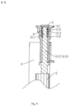
- the regulating mechanism 4 includes a knob 41, the knob 41 includes a knob body 411 and an insertion portion 412 arranged at the lower end of the knob body 411.
- the upper hinge hole 21 is arranged from top to bottom, and the lower end of the insertion part 412 is provided with an insertion hole 413.
- the insertion hole 413 is sleeved on the peripheral surface of the upper pivot 31, so that the knob 41 is fixed relative to the upper pivot 31 in the circumferential direction and is movable relative to the upper pivot 31 in the axial direction.
- the cross section of the insertion hole 413 is hexagonal, similarly, the cross section of the upper pivot 31 is also hexagonal, so as to achieve the technical effect that the knob 41 is fixed relative to the upper pivot 31 in the circumferential direction and is movable relative to the upper pivot 31 in the axial direction.
- the periphery of the knob body 411 is fixedly provided with a snap portion 414
- the hinged base 2 is provided with two open position snap slot 23 and closed position snap slot 24, wherein the open position snap slot and the closed position snap slot are configured for receiving of the snap portion 414.
- the snap portion 414 is snapped in the open position snap slot 23; in the closed state, the water separator 3 is driven to rotate by the rotation of the the knob 41 after the knob 41 is lifted up to separate the snap portion 414 from the open position snap slot 23, so as to make the snap portion 414 enter the closed position snap slot 24 to separate the accommodation space 10 of the water tank 1.
- the snap portion 414 can snap into the open position snap slot 23 or the closed position snap slot 24, respectively, to facilitate the maintenance of the post-variable volume of the water tank.
- the upper end of the knob body 411 is provided with a accommodation hole 415 communicated with the insertion hole 413, the accommodation hole 415 is larger than the maximum diameter of the insertion hole 413, so that a step 416 is formed between the accommodation hole 415 and the insertion hole 413.
- a fixing member 5 fixedly connected with the upper end of the upper pivot 31 is provided in the accommodation hole 415, and a spring 6 is arranged in the accommodation hole 415, and the spring is located between the fixing member 5 and the step 416 and sleeved on the outer circumference of the upper pivot 31.
- the spring 6 drives the snap portion 414 of the knob 41 to snap into the open position snap slot 23 or the closed position snap slot 24.
- One end of the spring 6 is against the step 416 and the other end of the spring is against the fixing member 5, so as to facilitate the knob 41 to enter the snap position after rotating, and then limit the rotation of the knob 41.
- a contact portion 33 is provided at the bottom end and the opposite end hinged with the hinged base 2 of the water separator 3, and the thickness of the contact portion 33 is less than that of the water separator 3.
- the water separator 3 is made of PP (polypropylene), and the thickness of the contact portion 33 of the water separator 3 is 0.1 to 0.5mm, so that the contact portion 33 has certain flexibility, which is conducive to the full contact between the contact portion 33 and the side wall and the bottom wall of the water tank 1, so that the water separator 3 has the effect of sealing and water separation.
- the upper pivot 31 is divided from top to bottom into a sleeve portion 311 configured to fixedly connect the fixing member 5 and a tight fitting portion 312 matched with the insertion hole 413, and a snap block 313 is arranged opposite to the outer circumference of the sleeve portion 311.
- the outer surface of the snap block 313 is inclined outward from top to bottom.
- the lower end of the fixing member 5 is provided with a sleeve hole 51, the outer circumference of the fixing member 5 is correspondingly provided with a snap opening 52 communicated with the sleeve hole 51 and corresponding to the snap block 313, and the fixing member 5 is correspondingly snapped into the snap block 313 through the snap opening 52.
- a notch 211 formed by penetrating from top to bottom is arranged on the side wall of the upper hinge hole 21.
- the radial width of the notch 211 is greater than the diameter of the upper pivot 31 and less than the diameter of the upper hinge hole 21.
- the specific installation steps are as follows: 1. First, assembling the lower pivot 32 in the lower hinge hole 22, and at the same time, assembling the upper pivot 31 in the upper hinge hole 21 through the notch 211 from outside to inside; 2. Inserting the insertion portion 412 of the knob 41 into the upper hinge hole 21 from top to bottom, so that the insertion hole 413 of the insertion portion 412 is sleeved on the peripheral surface of the upper pivot 31; 3. Putting the spring 6 on the outer circumference of the upper pivot 31; 4.
- two L-shaped fixing strips 11 are symmetrically arranged on the inner wall of the water tank 1, and the two L-shaped fixing strips 11 surround each other to form a plug-in slot 12 suitable for the hinged base 2, so as to facilitate the fixed installation of the hinged base 2 in the water tank.
Landscapes
- Health & Medical Sciences (AREA)
- Life Sciences & Earth Sciences (AREA)
- Engineering & Computer Science (AREA)
- Hydrology & Water Resources (AREA)
- Public Health (AREA)
- Water Supply & Treatment (AREA)
- Sanitary Device For Flush Toilet (AREA)
- Devices For Dispensing Beverages (AREA)
Claims (13)
- Wasserverbrauchsregulierungsvorrichtung, umfassend einen Wassertank (1), eine Scharnierbasis (2), die fest an einer Innenwand des Wassertanks (1) angeordnet ist, einen Wassertrenner (3), der an der Scharnierbasis (2) angelenkt ist, und einen Regulierungsmechanismus (4), der zwischen der Scharnierbasis (2) und dem Wassertrenner (3) bereitgestellt ist; wobei der Regulierungsmechanismus (4) dazu eingerichtet ist, den Wassertrenner (3) dazu anzutreiben, sich zu drehen, und zu fixieren, um einen Aufnahmeraum (10) des Wassertanks (1) zu teilen, wobei der Wassertrenner (3) an einem oberen Abschnitt eines seitlichen Endes einen oberen Drehzapfen (31) und an einem unteren Abschnitt des seitlichen Endes einen unteren Drehzapfen (32) aufweist, entsprechend an einem oberen Abschnitt und einem unteren Abschnitt der Scharnierbasis (2) ein oberes Scharnierloch (21) und ein unteres Scharnierloch (22) zum Einsetzen des oberen Drehzapfens (31) und des unteren Drehzapfens (32) angeordnet sind, und der Wassertrenner (3) über den oberen Drehzapfen (31) und den unteren Drehzapfen (32) entsprechend in das obere Scharnierloch (21) und das untere Scharnierloch (22) eingesetzt ist; wobei der Regulierungsmechanismus (4) einen Knauf (41) aufweist, der Knauf (41) einen Knaufkörper (411) und einen an einem unteren Ende des Knopfkörpers (411) bereitgestellten Einsetzabschnitt (412) aufweist, das obere Scharnierloch (21) von oben nach unten angeordnet ist, und ein unteres Ende des Einsetzabschnitts (412) mit einem Einsetzloch (413) versehen ist, wobei, nachdem der Knauf (41) mit dem Einsetzabschnitt (412) von oben nach unten in das obere Scharnierloch (21) eingesetzt ist, das Einsetzloch (413) auf eine Umfangsfläche des oberen Drehzapfens (31) aufgeschoben ist, so dass der Knauf (41) relativ zu dem oberen Drehzapfen (31) in einer Umfangsrichtung fixiert und relativ zu dem oberen Drehzapfen (31) in einer axialen Richtung beweglich ist; ein Umfang des Knaufkörpers (411) fest mit einem Schnappabschnitt (414) versehen ist, die Scharnierbasis (2) mit einem Schnappschlitz (23) für eine offene Position und einem Schnappschlitz (24) für eine geschlossene Position versehen ist, wobei der Schnappschlitz für die offene Position und der Schnappschlitz für die geschlossene Position dazu eingerichtet sind, den Schnappabschnitt (414) aufzunehmen; wobei in dem offenen Zustand der Schnappabschnitt (414) in den Schnappschlitz (23) für die offene Position eingeschnappt ist; in dem geschlossenen Zustand der Wassertrenner (3) durch Drehung des Knopfes (41) dazu angetrieben wird, sich zu drehen, nachdem der Knopf (41) angehoben worden ist, um den Schnappabschnitt (414) aus dem Schnappschlitz (23) für die offene Position zu lösen und den Schnappabschnitt (414) in den Schnappschlitz (24) für die geschlossene Position eintreten zu lassen, um den Aufnahmeraum (10) des Wassertanks (1) zu trennen.
- Wasserverbrauchsregulierungsvorrichtung nach Anspruch 1, dadurch gekennzeichnet, dass ein oberes Ende des Knaufkörpers (411) mit einem Aufnahmeloch (415) versehen ist, das mit dem Einsetzloch (413) in Verbindung steht, wobei das Aufnahmeloch (415) größer als ein maximaler Durchmesser des Einsetzlochs (413) ist, so dass eine Stufe (416) zwischen dem Aufnahmeloch (415) und dem Einsetzloch (413) ausgebildet ist; in dem Aufnahmeloch (415) ein Fixierelement (5) bereitgestellt ist, das fest mit einem oberen Ende des oberen Drehzapfens (31) verbunden ist, in dem Aufnahmeloch (415) eine Feder (6) angeordnet ist, die zwischen dem Fixierelement (5) und der Stufe (416) angeordnet ist und auf einen Außenumfang des oberen Drehzapfens (31) aufgeschoben ist, in dem Aufnahmeloch (415) angeordnet ist, wobei, wenn der Schnappabschnitt (414) des Knaufs (41) in eine Position gedreht wird, die dem Schnappschlitz (23) für die offene Position oder dem Schnappschlitz (24) für die geschlossene Position entspricht, die Feder (6) den Schnappabschnitt (414) des Knaufs (41) antreibt, so dass dieser in den Schnappschlitz (23) für die offene Position oder den Schnappschlitz (24) für die geschlossene Position einschnappt.
- Wasserverbrauchsregulierungsvorrichtung nach Anspruch 2, dadurch gekennzeichnet, dass an einem unteren Ende und an einem dem mit der Scharnierbasis (2) angelenkten Ende des Wassertrenners (3) ein Kontaktabschnitt (33) bereitgestellt ist, und eine Dicke des Kontaktabschnitts geringer als die des Wassertrenners (3) ist; und der Kontaktabschnitt (33) im geschlossenen Zustand an einer Seitenwand und einer Bodenwand des Wassertanks (1) anliegt.
- Wasserverbrauchsregulierungsvorrichtung nach Anspruch 1, dadurch gekennzeichnet, dass der obere Drehzapfen (31) von oben nach unten in einen Hülsenabschnitt (311), der dazu eingerichtet ist, das Fixierelement (5) fest zu verbinden, und einen Haftsitzabschnitt (312), der mit dem Einsetzloch (413) zusammenpasst, unterteilt ist, und gegenüber einem Außenumfang des Hülsenabschnitts (311) ein Schnappblock (313) angeordnet ist, ein unteres Ende des Fixierelements (5) mit einem Hülsenloch (51) bereitgestellt ist, ein Außenumfang des Fixierelements (5) entsprechend mit einer Schnappöffnung (52) bereitgestellt ist, die mit dem Hülsenloch (51) in Verbindung steht und dem Schnappblock (313) entspricht, und das Fixierelement (5) entsprechend durch die Schnappöffnung (52) in den Schnappblock (313) eingeschnappt ist.
- Wasserverbrauchsregulierungsvorrichtung nach Anspruch 4, dadurch gekennzeichnet, dass eine Außenfläche des Schnappblocks (313) von oben nach unten schräg nach außen verläuft.
- Wasserverbrauchsregulierungsvorrichtung nach Anspruch 1, dadurch gekennzeichnet, dass an einer Seitenwand des oberen Scharnierlochs (21) eine von oben nach unten eindringende Kerbe (211) ausgebildet ist.
- Wasserverbrauchsregulierungsvorrichtung nach Anspruch 6, dadurch gekennzeichnet, dass eine radiale Breite der Kerbe (211) größer als ein Durchmesser des oberen Drehzapfens (31) und kleiner als ein Durchmesser des oberen Scharnierlochs (21) ist.
- Wasserverbrauchsregulierungsvorrichtung nach Anspruch 1, dadurch gekennzeichnet, dass an der Innenwand des Wassertanks (1) zwei symmetrisch angeordnete, L-förmige Fixierleisten (11) angeordnet sind, und die zwei L-förmigen Fixierleisten (11) einen für die Scharnierbasis (2) geeigneten Einsteckschlitz (12) bilden.
- Wasserverbrauchsregulierungsvorrichtung nach Anspruch 1, dadurch gekennzeichnet, dass der Wassertrenner (3) aus Polypropylen hergestellt ist.
- Wasserverbrauchsregulierungsvorrichtung nach Anspruch 1, dadurch gekennzeichnet, dass ein Querschnitt des Einsetzlochs (413) sechseckig und ein Querschnitt des oberen Drehzapfens (31) sechseckig ist.
- Wasserverbrauchsregulierungsvorrichtung nach Anspruch 3, dadurch gekennzeichnet, dass die Dicke des Kontaktabschnitts (33) des Wassertrenners (3) 0,1 bis 0,5 mm beträgt.
- Wasserverbrauchsregulierungsvorrichtung nach Anspruch 1, dadurch gekennzeichnet, dass der Wassertrenner (3) den Aufnahmeraum (10) in zwei Teile teilt.
- Wasserverbrauchsregulierungsvorrichtung nach Anspruch 12, dadurch gekennzeichnet, dass ein Volumen des Wassertanks (1) durch die Regulierungsvorrichtung von 6 Litern auf 4,5 Liter geändert wird.
Applications Claiming Priority (1)
| Application Number | Priority Date | Filing Date | Title |
|---|---|---|---|
| CN202121976080.6U CN216041559U (zh) | 2021-08-21 | 2021-08-21 | 一种用于调节隐藏式水箱用水量的调节装置 |
Publications (3)
| Publication Number | Publication Date |
|---|---|
| EP4137647A1 EP4137647A1 (de) | 2023-02-22 |
| EP4137647C0 EP4137647C0 (de) | 2023-12-27 |
| EP4137647B1 true EP4137647B1 (de) | 2023-12-27 |
Family
ID=80559876
Family Applications (1)
| Application Number | Title | Priority Date | Filing Date |
|---|---|---|---|
| EP22156904.9A Active EP4137647B1 (de) | 2021-08-21 | 2022-02-15 | Regelungsvorrichtung zur regelung des wasserverbrauchs eines unterputzspülkastens |
Country Status (4)
| Country | Link |
|---|---|
| US (1) | US11959265B2 (de) |
| EP (1) | EP4137647B1 (de) |
| CN (1) | CN216041559U (de) |
| ES (1) | ES2973308T3 (de) |
Families Citing this family (1)
| Publication number | Priority date | Publication date | Assignee | Title |
|---|---|---|---|---|
| CN119642384B (zh) * | 2024-12-16 | 2026-01-23 | 珠海格力电器股份有限公司 | 一种水箱装置和冷风扇 |
Family Cites Families (10)
| Publication number | Priority date | Publication date | Assignee | Title |
|---|---|---|---|---|
| US946130A (en) * | 1909-07-09 | 1910-01-11 | Francis F Hawkins | Flushing device. |
| DE2216918A1 (de) * | 1972-03-30 | 1973-10-04 | Wilhelm Dipl Phys Dr Ing Baum | Zweikammer-spuelkasten fuer toiletten |
| US4009497A (en) * | 1972-04-19 | 1977-03-01 | Moon Walter Saver, Inc. | Water saving panel device for water closets |
| US4144600A (en) * | 1977-12-19 | 1979-03-20 | Robert Mayes | Liquid volume control for a liquid storage tank |
| US4388737A (en) * | 1981-10-16 | 1983-06-21 | Wenzel John G | Toilet tank insert water saver |
| US4419772A (en) * | 1982-01-12 | 1983-12-13 | Smith Clark K | Water saver |
| US6317899B1 (en) * | 2000-08-17 | 2001-11-20 | Niagara Conservation Corporation | Dual flush toilet |
| EP2205801B1 (de) * | 2007-09-24 | 2018-07-18 | Metaflush Pty Ltd | Spülkastenanordnung |
| FR2936000B1 (fr) * | 2008-09-17 | 2014-04-11 | Norberto Neves | Dispositif de chasse d'eau notamment pour cuvette de w.c. et ensemble de cuvette de w.c. et dispositif de chasse d'eau obtenu |
| KR101208147B1 (ko) * | 2010-10-16 | 2012-12-04 | 김영석 | 양변기 |
-
2021
- 2021-08-21 CN CN202121976080.6U patent/CN216041559U/zh active Active
-
2022
- 2022-02-15 ES ES22156904T patent/ES2973308T3/es active Active
- 2022-02-15 EP EP22156904.9A patent/EP4137647B1/de active Active
- 2022-02-22 US US17/676,927 patent/US11959265B2/en active Active
Also Published As
| Publication number | Publication date |
|---|---|
| EP4137647A1 (de) | 2023-02-22 |
| CN216041559U (zh) | 2022-03-15 |
| EP4137647C0 (de) | 2023-12-27 |
| ES2973308T3 (es) | 2024-06-19 |
| US11959265B2 (en) | 2024-04-16 |
| US20230057200A1 (en) | 2023-02-23 |
Similar Documents
| Publication | Publication Date | Title |
|---|---|---|
| CN102884255B (zh) | 洗净水箱装置及排水装置 | |
| CN112323931B (zh) | 一种杠杆式翻盖自动冲水马桶的操作方法 | |
| EP4137647A1 (de) | Regelungsvorrichtung zur regelung des wasserverbrauchs eines unterputzspülkastens | |
| JP2014185491A (ja) | 排水弁装置およびそれを備えた洗浄水タンク装置 | |
| CN106322766A (zh) | 热水器 | |
| CN107268739B (zh) | 一种抽水马桶的水箱结构 | |
| JP5441015B2 (ja) | 洗浄水タンク装置 | |
| CN211722945U (zh) | 一种农村环保无水无臭旱厕所马桶 | |
| US3566417A (en) | Combination toilet and holding tank | |
| CN204298916U (zh) | 节水蹲便器 | |
| CN209723156U (zh) | 高效节能型马桶水箱排水装置 | |
| CN218508583U (zh) | 一种具有节水功能的马桶水箱结构 | |
| US4419772A (en) | Water saver | |
| CN100567667C (zh) | 一种座便器水箱 | |
| CN221422167U (zh) | 一种建筑工程用给排水防堵塞装置 | |
| CN220301475U (zh) | 一种排放干管逆止装置 | |
| CN111255031B (zh) | 具有调节冲水速度功能的马桶冲水系统 | |
| CN220725289U (zh) | 一种应急厕所 | |
| KR200303598Y1 (ko) | 하수용 악취차단구 | |
| CN214017349U (zh) | 一种用于阻断流体的封挡装置及坐便器 | |
| CN216552310U (zh) | 一种具有密封机构的防臭味地漏 | |
| CN211690636U (zh) | 一种带小便器的冲水箱 | |
| CN2680745Y (zh) | 双排量排水装置 | |
| CN214093198U (zh) | 延时自闭阀芯 | |
| CN203531094U (zh) | 一种排水阀全排水位调节装置 |
Legal Events
| Date | Code | Title | Description |
|---|---|---|---|
| PUAI | Public reference made under article 153(3) epc to a published international application that has entered the european phase |
Free format text: ORIGINAL CODE: 0009012 |
|
| STAA | Information on the status of an ep patent application or granted ep patent |
Free format text: STATUS: REQUEST FOR EXAMINATION WAS MADE |
|
| 17P | Request for examination filed |
Effective date: 20220215 |
|
| AK | Designated contracting states |
Kind code of ref document: A1 Designated state(s): AL AT BE BG CH CY CZ DE DK EE ES FI FR GB GR HR HU IE IS IT LI LT LU LV MC MK MT NL NO PL PT RO RS SE SI SK SM TR |
|
| GRAP | Despatch of communication of intention to grant a patent |
Free format text: ORIGINAL CODE: EPIDOSNIGR1 |
|
| STAA | Information on the status of an ep patent application or granted ep patent |
Free format text: STATUS: GRANT OF PATENT IS INTENDED |
|
| RIC1 | Information provided on ipc code assigned before grant |
Ipc: E03D 1/22 20060101ALN20230824BHEP Ipc: E03D 1/14 20060101AFI20230824BHEP |
|
| INTG | Intention to grant announced |
Effective date: 20230925 |
|
| GRAS | Grant fee paid |
Free format text: ORIGINAL CODE: EPIDOSNIGR3 |
|
| GRAA | (expected) grant |
Free format text: ORIGINAL CODE: 0009210 |
|
| STAA | Information on the status of an ep patent application or granted ep patent |
Free format text: STATUS: THE PATENT HAS BEEN GRANTED |
|
| AK | Designated contracting states |
Kind code of ref document: B1 Designated state(s): AL AT BE BG CH CY CZ DE DK EE ES FI FR GB GR HR HU IE IS IT LI LT LU LV MC MK MT NL NO PL PT RO RS SE SI SK SM TR |
|
| REG | Reference to a national code |
Ref country code: GB Ref legal event code: FG4D |
|
| REG | Reference to a national code |
Ref country code: CH Ref legal event code: EP |
|
| REG | Reference to a national code |
Ref country code: DE Ref legal event code: R096 Ref document number: 602022001420 Country of ref document: DE |
|
| REG | Reference to a national code |
Ref country code: IE Ref legal event code: FG4D |
|
| U01 | Request for unitary effect filed |
Effective date: 20240112 |
|
| U07 | Unitary effect registered |
Designated state(s): AT BE BG DE DK EE FI FR IT LT LU LV MT NL PT SE SI Effective date: 20240123 |
|
| U20 | Renewal fee for the european patent with unitary effect paid |
Year of fee payment: 3 Effective date: 20240124 |
|
| PG25 | Lapsed in a contracting state [announced via postgrant information from national office to epo] |
Ref country code: GR Free format text: LAPSE BECAUSE OF FAILURE TO SUBMIT A TRANSLATION OF THE DESCRIPTION OR TO PAY THE FEE WITHIN THE PRESCRIBED TIME-LIMIT Effective date: 20240328 |
|
| PG25 | Lapsed in a contracting state [announced via postgrant information from national office to epo] |
Ref country code: GR Free format text: LAPSE BECAUSE OF FAILURE TO SUBMIT A TRANSLATION OF THE DESCRIPTION OR TO PAY THE FEE WITHIN THE PRESCRIBED TIME-LIMIT Effective date: 20240328 |
|
| PG25 | Lapsed in a contracting state [announced via postgrant information from national office to epo] |
Ref country code: RS Free format text: LAPSE BECAUSE OF FAILURE TO SUBMIT A TRANSLATION OF THE DESCRIPTION OR TO PAY THE FEE WITHIN THE PRESCRIBED TIME-LIMIT Effective date: 20231227 Ref country code: NO Free format text: LAPSE BECAUSE OF FAILURE TO SUBMIT A TRANSLATION OF THE DESCRIPTION OR TO PAY THE FEE WITHIN THE PRESCRIBED TIME-LIMIT Effective date: 20240327 Ref country code: HR Free format text: LAPSE BECAUSE OF FAILURE TO SUBMIT A TRANSLATION OF THE DESCRIPTION OR TO PAY THE FEE WITHIN THE PRESCRIBED TIME-LIMIT Effective date: 20231227 |
|
| REG | Reference to a national code |
Ref country code: ES Ref legal event code: FG2A Ref document number: 2973308 Country of ref document: ES Kind code of ref document: T3 Effective date: 20240619 |
|
| PG25 | Lapsed in a contracting state [announced via postgrant information from national office to epo] |
Ref country code: IS Free format text: LAPSE BECAUSE OF FAILURE TO SUBMIT A TRANSLATION OF THE DESCRIPTION OR TO PAY THE FEE WITHIN THE PRESCRIBED TIME-LIMIT Effective date: 20240427 |
|
| PG25 | Lapsed in a contracting state [announced via postgrant information from national office to epo] |
Ref country code: CZ Free format text: LAPSE BECAUSE OF FAILURE TO SUBMIT A TRANSLATION OF THE DESCRIPTION OR TO PAY THE FEE WITHIN THE PRESCRIBED TIME-LIMIT Effective date: 20231227 |
|
| PG25 | Lapsed in a contracting state [announced via postgrant information from national office to epo] |
Ref country code: SK Free format text: LAPSE BECAUSE OF FAILURE TO SUBMIT A TRANSLATION OF THE DESCRIPTION OR TO PAY THE FEE WITHIN THE PRESCRIBED TIME-LIMIT Effective date: 20231227 |
|
| PG25 | Lapsed in a contracting state [announced via postgrant information from national office to epo] |
Ref country code: SM Free format text: LAPSE BECAUSE OF FAILURE TO SUBMIT A TRANSLATION OF THE DESCRIPTION OR TO PAY THE FEE WITHIN THE PRESCRIBED TIME-LIMIT Effective date: 20231227 Ref country code: SK Free format text: LAPSE BECAUSE OF FAILURE TO SUBMIT A TRANSLATION OF THE DESCRIPTION OR TO PAY THE FEE WITHIN THE PRESCRIBED TIME-LIMIT Effective date: 20231227 Ref country code: RO Free format text: LAPSE BECAUSE OF FAILURE TO SUBMIT A TRANSLATION OF THE DESCRIPTION OR TO PAY THE FEE WITHIN THE PRESCRIBED TIME-LIMIT Effective date: 20231227 Ref country code: IS Free format text: LAPSE BECAUSE OF FAILURE TO SUBMIT A TRANSLATION OF THE DESCRIPTION OR TO PAY THE FEE WITHIN THE PRESCRIBED TIME-LIMIT Effective date: 20240427 Ref country code: CZ Free format text: LAPSE BECAUSE OF FAILURE TO SUBMIT A TRANSLATION OF THE DESCRIPTION OR TO PAY THE FEE WITHIN THE PRESCRIBED TIME-LIMIT Effective date: 20231227 |
|
| PG25 | Lapsed in a contracting state [announced via postgrant information from national office to epo] |
Ref country code: PL Free format text: LAPSE BECAUSE OF FAILURE TO SUBMIT A TRANSLATION OF THE DESCRIPTION OR TO PAY THE FEE WITHIN THE PRESCRIBED TIME-LIMIT Effective date: 20231227 |
|
| PG25 | Lapsed in a contracting state [announced via postgrant information from national office to epo] |
Ref country code: PL Free format text: LAPSE BECAUSE OF FAILURE TO SUBMIT A TRANSLATION OF THE DESCRIPTION OR TO PAY THE FEE WITHIN THE PRESCRIBED TIME-LIMIT Effective date: 20231227 |
|
| PG25 | Lapsed in a contracting state [announced via postgrant information from national office to epo] |
Ref country code: MC Free format text: LAPSE BECAUSE OF FAILURE TO SUBMIT A TRANSLATION OF THE DESCRIPTION OR TO PAY THE FEE WITHIN THE PRESCRIBED TIME-LIMIT Effective date: 20231227 |
|
| REG | Reference to a national code |
Ref country code: DE Ref legal event code: R097 Ref document number: 602022001420 Country of ref document: DE |
|
| PLBE | No opposition filed within time limit |
Free format text: ORIGINAL CODE: 0009261 |
|
| STAA | Information on the status of an ep patent application or granted ep patent |
Free format text: STATUS: NO OPPOSITION FILED WITHIN TIME LIMIT |
|
| 26N | No opposition filed |
Effective date: 20240930 |
|
| PG25 | Lapsed in a contracting state [announced via postgrant information from national office to epo] |
Ref country code: IE Free format text: LAPSE BECAUSE OF NON-PAYMENT OF DUE FEES Effective date: 20240215 |
|
| U20 | Renewal fee for the european patent with unitary effect paid |
Year of fee payment: 4 Effective date: 20241226 |
|
| PG25 | Lapsed in a contracting state [announced via postgrant information from national office to epo] |
Ref country code: IE Free format text: LAPSE BECAUSE OF NON-PAYMENT OF DUE FEES Effective date: 20240215 |
|
| PG25 | Lapsed in a contracting state [announced via postgrant information from national office to epo] |
Ref country code: CY Free format text: LAPSE BECAUSE OF FAILURE TO SUBMIT A TRANSLATION OF THE DESCRIPTION OR TO PAY THE FEE WITHIN THE PRESCRIBED TIME-LIMIT; INVALID AB INITIO Effective date: 20220215 |
|
| REG | Reference to a national code |
Ref country code: CH Ref legal event code: PL |
|
| PG25 | Lapsed in a contracting state [announced via postgrant information from national office to epo] |
Ref country code: CH Free format text: LAPSE BECAUSE OF NON-PAYMENT OF DUE FEES Effective date: 20250228 |
|
| PG25 | Lapsed in a contracting state [announced via postgrant information from national office to epo] |
Ref country code: TR Free format text: LAPSE BECAUSE OF FAILURE TO SUBMIT A TRANSLATION OF THE DESCRIPTION OR TO PAY THE FEE WITHIN THE PRESCRIBED TIME-LIMIT Effective date: 20231227 |
|
| U20 | Renewal fee for the european patent with unitary effect paid |
Year of fee payment: 5 Effective date: 20260128 |
|
| PGFP | Annual fee paid to national office [announced via postgrant information from national office to epo] |
Ref country code: GB Payment date: 20260129 Year of fee payment: 5 |
|
| PGFP | Annual fee paid to national office [announced via postgrant information from national office to epo] |
Ref country code: ES Payment date: 20260310 Year of fee payment: 5 |