EP4137339A1 - Water drainage assembly for a vehicle - Google Patents
Water drainage assembly for a vehicle Download PDFInfo
- Publication number
- EP4137339A1 EP4137339A1 EP22186440.8A EP22186440A EP4137339A1 EP 4137339 A1 EP4137339 A1 EP 4137339A1 EP 22186440 A EP22186440 A EP 22186440A EP 4137339 A1 EP4137339 A1 EP 4137339A1
- Authority
- EP
- European Patent Office
- Prior art keywords
- feed
- shell
- wall
- water drainage
- receptacle
- Prior art date
- Legal status (The legal status is an assumption and is not a legal conclusion. Google has not performed a legal analysis and makes no representation as to the accuracy of the status listed.)
- Pending
Links
Images

Classifications
-
- F—MECHANICAL ENGINEERING; LIGHTING; HEATING; WEAPONS; BLASTING
- F16—ENGINEERING ELEMENTS AND UNITS; GENERAL MEASURES FOR PRODUCING AND MAINTAINING EFFECTIVE FUNCTIONING OF MACHINES OR INSTALLATIONS; THERMAL INSULATION IN GENERAL
- F16L—PIPES; JOINTS OR FITTINGS FOR PIPES; SUPPORTS FOR PIPES, CABLES OR PROTECTIVE TUBING; MEANS FOR THERMAL INSULATION IN GENERAL
- F16L5/00—Devices for use where pipes, cables or protective tubing pass through walls or partitions
- F16L5/02—Sealing
- F16L5/10—Sealing by using sealing rings or sleeves only
-
- B—PERFORMING OPERATIONS; TRANSPORTING
- B60—VEHICLES IN GENERAL
- B60H—ARRANGEMENTS OF HEATING, COOLING, VENTILATING OR OTHER AIR-TREATING DEVICES SPECIALLY ADAPTED FOR PASSENGER OR GOODS SPACES OF VEHICLES
- B60H1/00—Heating, cooling or ventilating [HVAC] devices
- B60H1/32—Cooling devices
- B60H1/3233—Cooling devices characterised by condensed liquid drainage means
-
- B—PERFORMING OPERATIONS; TRANSPORTING
- B62—LAND VEHICLES FOR TRAVELLING OTHERWISE THAN ON RAILS
- B62D—MOTOR VEHICLES; TRAILERS
- B62D25/00—Superstructure or monocoque structure sub-units; Parts or details thereof not otherwise provided for
- B62D25/24—Superstructure sub-units with access or drainage openings having movable or removable closures; Sealing means therefor
Landscapes
- Engineering & Computer Science (AREA)
- Mechanical Engineering (AREA)
- General Engineering & Computer Science (AREA)
- Physics & Mathematics (AREA)
- Thermal Sciences (AREA)
- Chemical & Material Sciences (AREA)
- Combustion & Propulsion (AREA)
- Transportation (AREA)
- Body Structure For Vehicles (AREA)
Abstract
Die Erfindung betrifft eine Wasserablaufanordnung (10) für ein Fahrzeug, insbesondere für Kondenswasser eines Fahrzeugaggregats (1), mit einem Ablaufkanal (12), einer rohrförmigen Durchführvorrichtung (20), welche durch zwei in gegenüberliegende Wandbleche (5.1, 5.3) eingebrachte Rohbauöffnungen (5.2, 5.4) eines Hohlprofils (5) einer Fahrzeugkarosserie geführt ist, und einer rohbaufesten Hülse (16), welche eine erste der beiden Rohbauöffnungen (5.2, 5.4) des Hohlprofils (5) durchgreift und fluiddicht mit dem Hohlprofil (5) verbunden ist, wobei die Durchführvorrichtung (20) fluiddicht in die rohbaufeste Hülse (16) eingeführt ist und diese mit einem Ablauf (28) durchgreift, welcher an einem eingeführten Ende der Durchführvorrichtung (20) angeordnet ist, wobei der Ablaufkanal (12) mit seinem freien Ende fluiddicht in eine Aufnahme (22) der Durchführvorrichtung (20) eingeführt und gehalten ist, welche an einem dem Ablauf (28) gegenüberliegenden Ende der Durchführvorrichtung (20) angeordnet ist.

Description
Die Erfindung betrifft eine Wasserablaufanordnung für ein Fahrzeug, insbesondere für Kondenswasser eines Fahrzeugaggregats.The invention relates to a water drainage arrangement for a vehicle, in particular for condensation water from a vehicle unit.
Wasserablaufanordnungen für Fahrzeuge, insbesondere für Kondenswasser eines Fahrzeugaggregats, wie beispielsweise einer Klimaanlage sind in zahlreichen Variationen bekannt. Klimaanlagen werden in Fahrzeugen eingesetzt, um einen Fahrzeuginnenraum zu temperieren. Hierbei bewirkt die Klimaanlage, dass ein in den Fahrzeuginnenraum zugeführter Luftstrom in Abhängigkeit von den jeweiligen Erfordernissen erwärmt oder abgekühlt oder auf einer aktuellen Temperatur gehalten wird. Zudem wird dem zugeführten Luftstrom Feuchtigkeit entzogen. Um das resultierende abgeschiedene Wasser bzw. in der Klimaanlage entstehendes Kondenswasser abzuführen, werden in der Regel Wasserablaufanordnungen eingesetzt, welche vorzugsweise einen Ablaufkanal aufweisen, welcher das Wasser durch einen Durchbruch im Rohbau, vorzugsweise im Bereich eines Fahrzeugbodens, aus dem Fahrzeug ableitet.Water drainage arrangements for vehicles, in particular for condensed water from a vehicle unit, such as an air conditioning system, are known in numerous variations. Air conditioners are used in vehicles to control the temperature of a vehicle interior. In this case, the air conditioning system causes an air flow fed into the vehicle interior to be heated or cooled or kept at a current temperature, depending on the respective requirements. In addition, moisture is extracted from the supplied air flow. In order to drain the resulting separated water or condensation water that forms in the air conditioning system, water drain arrangements are generally used, which preferably have a drain channel which drains the water out of the vehicle through an opening in the shell, preferably in the area of a vehicle floor.
Aus der
Aus der
Aus der
Aus der
Aus der
Der Erfindung liegt die Aufgabe zu Grunde, eine Wasserablaufanordnung für ein Fahrzeug bereitzustellen, welche eine einfache Wasserabscheidung durch einen Hohlprofil ermöglicht.The invention is based on the object of providing a water drainage arrangement for a vehicle which enables simple water separation through a hollow profile.
Diese Aufgabe wird durch eine Wasserablaufanordnung für ein Fahrzeug mit den Merkmalen des Patentanspruchs 1 gelöst. Vorteilhafte Ausgestaltungen mit zweckmäßigen Weiterbildungen der Erfindung sind in den abhängigen Patentansprüchen angegeben.This object is achieved by a water drainage arrangement for a vehicle having the features of claim 1. Advantageous configurations with expedient developments of the invention are specified in the dependent patent claims.
Um eine Wasserablaufanordnung für ein Fahrzeug bereitzustellen, welche eine einfache Wasserabscheidung durch ein Hohlprofil ermöglicht, umfasst die Wasserablaufanordnung für ein Fahrzeug einen Ablaufkanal, eine rohrförmige Durchführvorrichtung, welche durch zwei in gegenüberliegende Wandbleche eingebrachte Rohbauöffnungen eines Hohlprofils einer Fahrzeugkarosserie geführt ist, und eine rohbaufeste Hülse, welche eine erste der beiden Rohbauöffnungen des Hohlprofils durchgreift und fluiddicht mit dem Hohlprofil verbunden ist. Hierbei ist die Durchführvorrichtung fluiddicht in die rohbaufeste Hülse eingeführt und durchgreift diese mit einem Ablauf, welcher an einem eingeführten Ende der Durchführvorrichtung angeordnet ist. Der Ablaufkanal ist mit seinem freien Ende fluiddicht in eine Aufnahme der Durchführvorrichtung eingeführt und gehalten, welche an einem dem Ablauf gegenüberliegenden Ende der Durchführvorrichtung angeordnet ist. Hierbei ist an einer Außenwand der rohbaufesten Hülse ein umlaufender erster Dichtkragen ausgebildet, welcher mit einem korrespondierenden ersten Wandblech des Hohlprofils verbunden ist und als Abdeckscheibe wirkt, welche die erste Rohbauöffnung im ersten Wandblech dichtend abdeckt. Die rohbaufeste Hülse kann vorzugsweise als Metallhülse ausgeführt werden. Der erste Dichtkragen kann mit dem erste Wandblech beispielsweise verschweißt oder verklebt sein. Zudem ist an einer Außenwand der Aufnahme der Durchführvorrichtung ein umlaufender zweiter Dichtkragen ausgebildet, welcher auf einem korrespondierenden zweiten Wandblech des Hohlprofils aufliegt und als Abdeckscheibe wirkt, welche eine zweite Rohbauöffnung im zweiten Wandblech des Hohlprofils dichtend abdeckt. Durch das Schließen der Rohbauöffnung mit Hilfe des zweiten Dichtkragens, kann eine akustische Abdichtung des Hohlprofils erreicht werden.In order to provide a water drainage arrangement for a vehicle, which enables simple water separation through a hollow profile, the water drainage arrangement for a vehicle comprises a drainage channel, a tubular feed-through device, which is guided through two body shell openings of a hollow profile of a vehicle body made in opposite wall panels, and a sleeve fixed to the body shell, which passes through a first of the two shell openings of the hollow profile and is connected to the hollow profile in a fluid-tight manner. In this case, the feed-through device is introduced in a fluid-tight manner into the shell-fixed sleeve and penetrates this with a drain, which is arranged at an inserted end of the feed-through device. The free end of the discharge channel is inserted and held in a fluid-tight manner in a receptacle of the feed-through device, which is arranged at an end of the feed-through device opposite the discharge. Here is at one Outer wall of the shell-fixed sleeve formed a circumferential first sealing collar, which is connected to a corresponding first wall panel of the hollow profile and acts as a cover plate, which covers the first shell opening in the first wall panel sealing. The shell-fixed sleeve can preferably be designed as a metal sleeve. The first sealing collar can be welded or glued to the first wall panel, for example. In addition, a circumferential second sealing collar is formed on an outer wall of the receptacle of the feed-through device, which rests on a corresponding second wall panel of the hollow profile and acts as a cover disk, which sealingly covers a second shell opening in the second wall panel of the hollow profile. By closing the shell opening with the help of the second sealing collar, acoustic sealing of the hollow profile can be achieved.
Bei Ausführungsformen der erfindungsgemäßen Wasserablaufanordnung für ein Fahrzeug wird abgeschiedenes Wasser bzw. Kondenswasser mittels der Durchführvorrichtung durch das Hohlprofil geleitet, ohne dass dieses in das Hohlprofil eindringen kann. Zudem dichten Ausführungsformen der erfindungsgemäßen Wasserablaufanordnung für ein Fahrzeug das Fahrzeug auch gegen Wasser von unten ab, welches bei einer Wasserdurchfahrt durch den Ablauf der Durchführvorrichtung eindringen könnte. Die Durchführvorrichtung kann vorzugsweise aus einem Ethylen-Propylen-Dien-Monomer-Kautschuk (EPDM-Kautschuk) hergestellt sein. Bei dem Hohlprofil kann es sich beispielsweise um einen Querträger handeln, welcher im Bodenbereich des Fahrzeugs angeordnet ist.In embodiments of the water drainage arrangement according to the invention for a vehicle, separated water or condensed water is conducted through the hollow profile by means of the feed-through device without being able to penetrate into the hollow profile. In addition, embodiments of the water drainage arrangement according to the invention for a vehicle also seal the vehicle from below against water, which could penetrate through the drainage of the feed-through device when driving through water. The feed-through device may preferably be made of an ethylene propylene diene monomer rubber (EPDM rubber). The hollow profile can be a cross member, for example, which is arranged in the floor area of the vehicle.
Vorzugsweise kann zwischen dem ersten Dichtkragen und dem ersten Wandblech ein Dichtelement angeordnet sein. Das Dichtelement kann beispielsweise als Gummidichtscheibe oder als Gummibeschichtung ausgeführt sein. Da die bevorzugte Montagerichtung der Wasserablaufanordnung von oben ist, entspricht das erste Wandblechs des Hohlprofils vorzugsweise einem unteren Wandblech, welches einen äußeren Abschluss des Fahrzeugs ausbildet. Die Durchführvorrichtung kann dann in einem Arbeitsschritt von oben durch eine zweite Rohbauöffnung in einem zweiten oberen Wandblech, welches dem Fahrzeuginneren zugewandt ist, in die rohbaufeste Hülse eingeführt werden.A sealing element can preferably be arranged between the first sealing collar and the first wall plate. The sealing element can be designed, for example, as a rubber sealing disk or as a rubber coating. Since the preferred mounting direction of the water drainage arrangement is from above, the first wall panel of the hollow profile preferably corresponds to a lower wall panel, which forms an outer closure of the vehicle. The implementation device can then in one step from above by a second shell opening in a second upper wall panel, which faces the vehicle interior, are introduced into the shell-fixed sleeve.
In weiterer vorteilhafter Ausgestaltung der Wasserablaufanordnung kann an einer Außenwand des Ablaufs mindestens eine Rückzugssicherung ausgebildet sein, welche im montierten Zustand auf dem ersten Dichtkragen der rohbaufesten Hülse aufliegt. Hierzu kann die mindestens eine Rückzugssicherung beispielsweise als elastische Rastnase ausgeführt sein. Vorzugsweise sind zwei Rastnasen einander gegenüberliegend an der Außenwand des Ablaufs angeordnet. Um die Elastizität beim Einführen der Durchführvorrichtung in die rohbaufeste Hülse zu erhalten, können längliche Aussparungen zwischen den Rastnasen in den Ablauf eingebracht sein.In a further advantageous embodiment of the water drain arrangement, at least one anti-return device can be formed on an outer wall of the drain, which in the mounted state rests on the first sealing collar of the shell-fixed sleeve. For this purpose, the at least one anti-retraction device can be designed, for example, as an elastic latching lug. Two latching lugs are preferably arranged opposite one another on the outer wall of the drain. In order to maintain the elasticity when inserting the feed-through device into the shell-fixed sleeve, oblong recesses can be introduced between the latching lugs in the outlet.
In weiterer vorteilhafter Ausgestaltung der Wasserablaufanordnung kann zwischen der Aufnahme und dem Ablauf eine erste Dichtung an der Durchführvorrichtung angeordnet sein, welche dichtend mit der rohbaufesten Hülse zusammenwirken kann. Die erste Dichtung kann mindestens eine gummielastische Dichtlippe aufweisen, welche vorzugsweise an die Außenwand der Durchführvorrichtung angespritzt werden und dichtend an einer Innenwand der rohbaufesten Hülse anliegen kann. Um die Dichtwirkung zu erhöhen, kann die erste Dichtung vorzugsweise mehrere gummielastische Dichtlippen aufweisen.In a further advantageous embodiment of the water drain arrangement, a first seal can be arranged on the feed-through device between the receptacle and the drain, which seal can interact with the shell-fixed sleeve in a sealing manner. The first seal can have at least one rubber-elastic sealing lip, which can preferably be molded onto the outer wall of the feed-through device and can rest sealingly against an inner wall of the shell-fixed sleeve. In order to increase the sealing effect, the first seal can preferably have a plurality of rubber-elastic sealing lips.
In weiterer vorteilhafter Ausgestaltung der Wasserablaufanordnung kann am freien Ende der Aufnahme der Durchführvorrichtung ein Einführtrichter ausgebildet sein. Dadurch kann des Einführen und Zentrieren des Ablaufkanals in die Aufnahme der Durchführvorrichtung erleichtert werden. Zudem kann an einer Innenwand der Aufnahme der Durchführvorrichtung ein Anschlag ausgebildet sein, welcher die Einführtiefe des Ablaufkanals vorgibt. Durch den Anschlag erhält ein Arbeiter beim Einführen des Ablaufkanals in die Aufnahme Durchführvorrichtung eine haptische Rückmeldung, wenn die vorgegebene Einführtiefe für den Ablaufkanal erreicht ist. Der Anschlag kann beispielsweise dadurch umgesetzt werden, dass eine Durchgangsöffnung der Durchführvorrichtung gestuft mit unterschiedlichen Durchmessern ausgeführt sein kann. So können beispielsweise die Aufnahme und der Ablauf der Durchführvorrichtung jeweils einen größeren Innendurchmesser als ein Zwischenstück zwischen der Aufnahme und dem Ablauf aufweisen.In a further advantageous embodiment of the water drainage arrangement, an insertion funnel can be formed at the free end of the receptacle of the feed-through device. This can facilitate the insertion and centering of the drainage channel into the receptacle of the feed-through device. In addition, a stop can be formed on an inner wall of the receptacle of the feed-through device, which defines the insertion depth of the drainage channel. Through the stop, a worker receives haptic feedback when inserting the drainage channel into the feed-through device when the predetermined insertion depth for the drainage channel has been reached. The stop can be implemented, for example, in that a through-opening of the feed-through device can be designed in a stepped manner with different diameters. So For example, the receptacle and the outlet of the feed-through device can each have a larger inner diameter than an intermediate piece between the receptacle and the outlet.
In weiterer vorteilhafter Ausgestaltung der Wasserablaufanordnung kann am freien Ende des Ablaufkanals eine zweite Dichtung angeordnet sein, welche dichtend mit der Aufnahme der Durchführvorrichtung zusammenwirken kann. Die zweite Dichtung kann mindestens eine gummielastische Dichtlippe aufweisen, welche vorzugsweise an die Außenwand der Ablaufkanals angespritzt werden und dichtend an der Innenwand der Aufnahme der Durchführvorrichtung anliegen kann. Um die Dichtwirkung zu erhöhen, kann die zweite Dichtung vorzugsweise mehrere gummielastische Dichtlippen aufweisen.In a further advantageous embodiment of the water drainage arrangement, a second seal can be arranged at the free end of the drainage channel, which can interact in a sealing manner with the receptacle of the feed-through device. The second seal can have at least one rubber-elastic sealing lip, which can preferably be injection molded onto the outer wall of the discharge channel and can rest against the inner wall of the receptacle of the feed-through device in a sealing manner. In order to increase the sealing effect, the second seal can preferably have several rubber-elastic sealing lips.
Die vorstehend in der Beschreibung genannten Merkmale und Merkmalskombinationen sowie die nachfolgend in der Figurenbeschreibung genannten und/oder in den Figuren alleine gezeigten Merkmale und Merkmalskombinationen sind nicht nur in der jeweils angegebenen Kombination, sondern auch in anderen Kombinationen oder in Alleinstellung verwendbar, ohne den Rahmen der Erfindung zu verlassen. Es sind somit auch Ausführungen als von der Erfindung umfasst und offenbart anzusehen, die in den Figuren nicht explizit gezeigt oder erläutert sind, jedoch durch separierte Merkmalskombinationen aus den erläuterten Ausführungen hervorgehen und erzeugbar sind.The features and combinations of features mentioned above in the description and the features and combinations of features mentioned below in the description of the figures and/or shown alone in the figures can be used not only in the combination specified in each case, but also in other combinations or on their own, without going beyond the scope of the leave invention. Embodiments are therefore also to be regarded as included and disclosed by the invention which are not explicitly shown or explained in the figures, but which result from the explained embodiments and can be generated by means of separate combinations of features.
Ein Ausführungsbeispiel der Erfindung ist in den Zeichnungen dargestellt und wird in der nachfolgenden Beschreibung näher erläutert. In den Zeichnungen bezeichnen gleiche Bezugszeichen Komponenten bzw. Elemente, die gleiche bzw. analoge Funktionen ausführen. Hierbei zeigen:
- Fig. 1
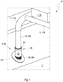
- eine schematische und perspektivische Darstellung eines Aus-schnitts eines Fahrzeugbodens mit einem Ausführungsbeispiel einer erfindungsgemäßen Wasserablaufanordnung für ein Fahrzeug; und
- Fig. 2
- eine schematische Schnittdarstellung der erfindungsgemäßen Wasserablaufanordnung für ein Fahrzeug aus
Fig. 1 .
- 1
- a schematic and perspective view of a section of a vehicle floor with an embodiment of a water drainage arrangement according to the invention for a vehicle; and
- 2
- a schematic sectional view of the water drainage arrangement according to the invention for a vehicle
1 .
Wie aus
Im dargestellten Ausführungsbeispiel wird die Wasserablaufanordnung 10 zum Ableiten von Kondenswasser eines Fahrzeugaggregats 1 eingesetzt, welches hier einer Klimaanlage 1A entspricht. Hierzu ist mindestens ein Zulaufkanal 11 mit dem Ablaufkanal 12 verbunden, um das Kondenswasser des Fahrzeugaggregats 1 abzuleiten. Wie aus
Wie aus
Wie aus
In einem alternativen nicht dargestellten Ausführungsbeispiel ist der erste Dichtkragen 18 der rohbaufesten Hülse 16 mit dem ersten Wandblech 5.1 des Hohlkörpers 5 verklebt. Hierbei wirkt die Kleberschicht gleichzeitig als Dichtelement zwischen dem Dichtkragen 18 der rohbaufesten Hülse 16 und dem ersten Wandblech 5.1 des Hohlkörpers.In an alternative exemplary embodiment, which is not shown, the first sealing collar 18 of the
Wie aus
Wie aus
Wie aus
Wie aus
Wie aus
- 11
- Fahrzeugaggregatvehicle aggregate
- 1A1A
- Klimaanlageair conditioner
- 33
- Fahrzeugbodenvehicle floor
- 55
- Hohlprofilhollow profile
- 5A5A
- Querträgercross member
- 5.15.1
- erstes (unteres) Wandblechfirst (bottom) wall panel
- 5.25.2
- erste Rohbauöffnungfirst shell opening
- 5.35.3
- zweites (oberes) Wandblechsecond (top) wall panel
- 5.45.4
- zweite Rohbauöffnungsecond shell opening
- 1010
- Wasserablaufanordnungwater drainage arrangement
- 11, 11A, 11B11, 11A, 11B
- Zulaufkanalinlet channel
- 1212
- Ablaufkanaldrain channel
- 12A12A
- SchlauchHose
- 1414
- zweite Dichtungsecond seal
- 14A14A
- Dichtlippesealing lip
- 1616
- rohbaufeste Hülseshell-fixed sleeve
- 1818
- erster Dichtkragenfirst sealing collar
- 18A18A
- Abdeckscheibecover disc
- 2020
- Durchführvorrichtungfeed-through device
- 2222
- AufnahmeRecording
- 22.122.1
- Anschlagattack
- 2424
- Einführtrichterinsertion funnel
- 2626
- zweiter Dichtkragensecond sealing collar
- 26A26A
- Abdeckscheibecover disc
- 2727
- erste Dichtungfirst seal
- 27A27A
- Dichtlippesealing lip
- 2828
- AblaufSequence
- 28.128.1
- Aussparungrecess
- 2929
- Rückzugssicherungretraction protection
- 29A29A
- elastische Rastnaseelastic latch
Claims (8)
dadurch gekennzeichnet,
dass zwischen dem ersten Dichtkragen (18) und dem ersten Wandblech (5.1) ein Dichtelement angeordnet ist.Water drainage arrangement (10) according to claim 1,
characterized,
that a sealing element is arranged between the first sealing collar (18) and the first wall plate (5.1).
dadurch gekennzeichnet,
dass an einer Außenwand des Ablaufs (28) mindestens eine Rückzugssicherung (29) ausgebildet ist, welche im montierten Zustand auf dem ersten Dichtkragen (18) der rohbaufesten Hülse (16) aufliegt.Water drainage arrangement (10) according to claim 1 or 2,
characterized,
that at least one anti-return device (29) is formed on an outer wall of the outlet (28), which in the mounted state rests on the first sealing collar (18) of the sleeve (16) fixed to the shell.
dass zwischen der Aufnahme (22) und dem Ablauf (28) eine erste Dichtung (27) an der Durchführvorrichtung (20) angeordnet ist, welche dichtend mit der rohbaufesten Hülse (16) zusammenwirkt.Water drainage arrangement (10) according to one of Claims 1 to 3, characterized in that
that a first seal (27) is arranged on the feed-through device (20) between the receptacle (22) and the outlet (28), which seal interacts with the sleeve (16) fixed to the bodyshell.
dass am freien Ende der Aufnahme (22) der Durchführvorrichtung (20) ein Einführtrichter (24) ausgebildet ist.Water drainage arrangement (10) according to one of Claims 1 to 4, characterized in that
that an insertion funnel (24) is formed at the free end of the receptacle (22) of the feed-through device (20).
dass an einer Innenwand der Aufnahme (22) der Durchführvorrichtung (20) ein Anschlag (22.1) ausgebildet ist, welcher die Einführtiefe des Ablaufkanals (12) vorgibt.Water drainage arrangement (10) according to one of Claims 1 to 5, characterized in that
that on an inner wall of the receptacle (22) of the feed-through device (20) a stop (22.1) is formed, which specifies the insertion depth of the drainage channel (12).
dass am freien Ende des Ablaufkanals (12) eine zweite Dichtung (14) angeordnet ist, welche dichtend mit der Aufnahme (22) der Durchführvorrichtung (20) zusammenwirkt.Water drainage arrangement (10) according to one of Claims 1 to 6, characterized in that
that at the free end of the discharge channel (12) there is a second seal (14) which cooperates in a sealing manner with the receptacle (22) of the feed-through device (20).
dadurch gekennzeichnet,
dass die Dichtung (14, 27) mindestens eine gummielastische Dichtlippe (14A, 27A) aufweist.Water drainage arrangement (10) according to claim 4 or 7,
characterized,
that the seal (14, 27) has at least one rubber-elastic sealing lip (14A, 27A).
Applications Claiming Priority (1)
| Application Number | Priority Date | Filing Date | Title |
|---|---|---|---|
| DE102021121525.0A DE102021121525A1 (en) | 2021-08-19 | 2021-08-19 | Water drainage arrangement for a vehicle |
Publications (1)
| Publication Number | Publication Date |
|---|---|
| EP4137339A1 true EP4137339A1 (en) | 2023-02-22 |
Family
ID=82701830
Family Applications (1)
| Application Number | Title | Priority Date | Filing Date |
|---|---|---|---|
| EP22186440.8A Pending EP4137339A1 (en) | 2021-08-19 | 2022-07-22 | Water drainage assembly for a vehicle |
Country Status (4)
| Country | Link |
|---|---|
| US (1) | US20230054946A1 (en) |
| EP (1) | EP4137339A1 (en) |
| CN (1) | CN115923432A (en) |
| DE (1) | DE102021121525A1 (en) |
Citations (7)
| Publication number | Priority date | Publication date | Assignee | Title |
|---|---|---|---|---|
| JPS59223515A (en) * | 1983-06-02 | 1984-12-15 | Nissan Motor Co Ltd | Installing structure for cleaning unit |
| DE19816331C1 (en) * | 1998-04-11 | 1999-09-23 | Daimler Chrysler Ag | Condensation outlet tube for motor vehicle air conditioning |
| FR2911815A1 (en) | 2007-01-31 | 2008-08-01 | Peugeot Citroen Automobiles Sa | Soundproofing system for evacuating water vapor of air conditioner, has walls i.e. rows, of labyrinth forming long labyrinth path in compact space for acoustic waves of noise coming from exterior by outlet of condensates |
| DE102009009065A1 (en) | 2009-02-16 | 2010-08-19 | Behr Gmbh & Co. Kg | Air conditioning for a motor vehicle |
| DE112014006214T5 (en) | 2014-01-20 | 2016-11-03 | Hanon Systems | Air conditioning system for motor vehicles |
| CN111824192A (en) | 2020-07-30 | 2020-10-27 | 中车株洲电力机车有限公司 | Straight-line air exhaust and drainage structure of rail transit vehicle |
| DE102019207800A1 (en) | 2019-05-28 | 2020-12-03 | Mahle International Gmbh | Condensate drainage device |
-
2021
- 2021-08-19 DE DE102021121525.0A patent/DE102021121525A1/en active Pending
-
2022
- 2022-07-22 EP EP22186440.8A patent/EP4137339A1/en active Pending
- 2022-08-18 US US17/820,740 patent/US20230054946A1/en active Pending
- 2022-08-18 CN CN202210990515.5A patent/CN115923432A/en active Pending
Patent Citations (7)
| Publication number | Priority date | Publication date | Assignee | Title |
|---|---|---|---|---|
| JPS59223515A (en) * | 1983-06-02 | 1984-12-15 | Nissan Motor Co Ltd | Installing structure for cleaning unit |
| DE19816331C1 (en) * | 1998-04-11 | 1999-09-23 | Daimler Chrysler Ag | Condensation outlet tube for motor vehicle air conditioning |
| FR2911815A1 (en) | 2007-01-31 | 2008-08-01 | Peugeot Citroen Automobiles Sa | Soundproofing system for evacuating water vapor of air conditioner, has walls i.e. rows, of labyrinth forming long labyrinth path in compact space for acoustic waves of noise coming from exterior by outlet of condensates |
| DE102009009065A1 (en) | 2009-02-16 | 2010-08-19 | Behr Gmbh & Co. Kg | Air conditioning for a motor vehicle |
| DE112014006214T5 (en) | 2014-01-20 | 2016-11-03 | Hanon Systems | Air conditioning system for motor vehicles |
| DE102019207800A1 (en) | 2019-05-28 | 2020-12-03 | Mahle International Gmbh | Condensate drainage device |
| CN111824192A (en) | 2020-07-30 | 2020-10-27 | 中车株洲电力机车有限公司 | Straight-line air exhaust and drainage structure of rail transit vehicle |
Also Published As
| Publication number | Publication date |
|---|---|
| DE102021121525A1 (en) | 2023-02-23 |
| CN115923432A (en) | 2023-04-07 |
| US20230054946A1 (en) | 2023-02-23 |
Similar Documents
| Publication | Publication Date | Title |
|---|---|---|
| DE10109176A1 (en) | Cross strut arrangement made of plastic for a vehicle with shaft connectors formed uniformly with it | |
| DE102007031850A1 (en) | driving device | |
| EP2062761B1 (en) | Air conditioning unit for a motor vehicle | |
| DE102015212593A1 (en) | Sealing arrangement and ventilation, heating or air conditioning with such a seal arrangement | |
| DE102015113538A1 (en) | HAVC channel with pivoting bow | |
| DE102009020060A1 (en) | Vehicle air conditioning assembly for use in vehicle, comprises air conditioning housing, and air connection portions for connection of separate air duct | |
| EP1926635A1 (en) | Motor vehicle door | |
| EP4137339A1 (en) | Water drainage assembly for a vehicle | |
| DE19949587C2 (en) | Protection unit for electrical devices | |
| DE19835704A1 (en) | Vehicle bodywork section including flexible plastic pipe or duct is made expeditiously by adding pipe before closing seams and selecting suitable plastic | |
| DE10315381A1 (en) | Water drain for motor vehicle has one-piece hose extending through opening in body of vehicle, and additional means of fastening with fastening element and elastic attachment element | |
| DE4436778A1 (en) | Cable or tube wall-entrance with through-panel sealing element for motor vehicles | |
| DE102015012505A1 (en) | Sealing arrangement for a connection device and connection device for an air conditioner | |
| EP1318928B1 (en) | Cable bushing on a vehicle door | |
| DE202018100866U1 (en) | Integrated sunroof drainage pipe | |
| DE19930900A1 (en) | poetry | |
| EP1394459B1 (en) | Component bond | |
| DE102016209931A1 (en) | Arrangement for collecting and removing leaked refrigerant | |
| DE102020104123A1 (en) | End piece for a cover and bowden cable | |
| DE10353666B4 (en) | Modular air conditioning | |
| DE19605994C1 (en) | Housing for electronic control apparatus in motor vehicle | |
| DE10307979A1 (en) | Passenger vehicle includes splash shield having two portions secured to one another defining air passageway in communication with engine | |
| DE102008010023A1 (en) | Air flow equalization element i.e. grating, arrangement for air duct of motor vehicle ventilation system, arranges equalization element in air duct using oscillation-decoupling elements, which are designed as molded elastomeric part | |
| EP1437504B1 (en) | Air silencer for an automotive air temperature conditioning apparatus | |
| EP1970233A1 (en) | Device for providing air conditioning for air fed into an automobile interior |
Legal Events
| Date | Code | Title | Description |
|---|---|---|---|
| PUAI | Public reference made under article 153(3) epc to a published international application that has entered the european phase |
Free format text: ORIGINAL CODE: 0009012 |
|
| STAA | Information on the status of an ep patent application or granted ep patent |
Free format text: STATUS: THE APPLICATION HAS BEEN PUBLISHED |
|
| AK | Designated contracting states |
Kind code of ref document: A1 Designated state(s): AL AT BE BG CH CY CZ DE DK EE ES FI FR GB GR HR HU IE IS IT LI LT LU LV MC MK MT NL NO PL PT RO RS SE SI SK SM TR |
|
| P01 | Opt-out of the competence of the unified patent court (upc) registered |
Effective date: 20230529 |