EP4137060A1 - Curved ultrasound probe - Google Patents
Curved ultrasound probe Download PDFInfo
- Publication number
- EP4137060A1 EP4137060A1 EP21315138.4A EP21315138A EP4137060A1 EP 4137060 A1 EP4137060 A1 EP 4137060A1 EP 21315138 A EP21315138 A EP 21315138A EP 4137060 A1 EP4137060 A1 EP 4137060A1
- Authority
- EP
- European Patent Office
- Prior art keywords
- ultrasound
- hand probe
- curved
- probe
- accessory device
- Prior art date
- Legal status (The legal status is an assumption and is not a legal conclusion. Google has not performed a legal analysis and makes no representation as to the accuracy of the status listed.)
- Withdrawn
Links
Images

Classifications
-
- A—HUMAN NECESSITIES
- A61—MEDICAL OR VETERINARY SCIENCE; HYGIENE
- A61B—DIAGNOSIS; SURGERY; IDENTIFICATION
- A61B8/00—Diagnosis using ultrasonic, sonic or infrasonic waves
- A61B8/42—Details of probe positioning or probe attachment to the patient
- A61B8/4209—Details of probe positioning or probe attachment to the patient by using holders, e.g. positioning frames
-
- A—HUMAN NECESSITIES
- A61—MEDICAL OR VETERINARY SCIENCE; HYGIENE
- A61B—DIAGNOSIS; SURGERY; IDENTIFICATION
- A61B5/00—Measuring for diagnostic purposes; Identification of persons
- A61B5/68—Arrangements of detecting, measuring or recording means, e.g. sensors, in relation to patient
- A61B5/6801—Arrangements of detecting, measuring or recording means, e.g. sensors, in relation to patient specially adapted to be attached to or worn on the body surface
- A61B5/6813—Specially adapted to be attached to a specific body part
- A61B5/6825—Hand
- A61B5/6826—Finger
-
- A—HUMAN NECESSITIES
- A61—MEDICAL OR VETERINARY SCIENCE; HYGIENE
- A61B—DIAGNOSIS; SURGERY; IDENTIFICATION
- A61B8/00—Diagnosis using ultrasonic, sonic or infrasonic waves
- A61B8/08—Clinical applications
- A61B8/0891—Clinical applications for diagnosis of blood vessels
-
- A—HUMAN NECESSITIES
- A61—MEDICAL OR VETERINARY SCIENCE; HYGIENE
- A61B—DIAGNOSIS; SURGERY; IDENTIFICATION
- A61B8/00—Diagnosis using ultrasonic, sonic or infrasonic waves
- A61B8/42—Details of probe positioning or probe attachment to the patient
- A61B8/4209—Details of probe positioning or probe attachment to the patient by using holders, e.g. positioning frames
- A61B8/4227—Details of probe positioning or probe attachment to the patient by using holders, e.g. positioning frames characterised by straps, belts, cuffs or braces
-
- A—HUMAN NECESSITIES
- A61—MEDICAL OR VETERINARY SCIENCE; HYGIENE
- A61B—DIAGNOSIS; SURGERY; IDENTIFICATION
- A61B8/00—Diagnosis using ultrasonic, sonic or infrasonic waves
- A61B8/44—Constructional features of the ultrasonic, sonic or infrasonic diagnostic device
- A61B8/4444—Constructional features of the ultrasonic, sonic or infrasonic diagnostic device related to the probe
- A61B8/4455—Features of the external shape of the probe, e.g. ergonomic aspects
-
- A—HUMAN NECESSITIES
- A61—MEDICAL OR VETERINARY SCIENCE; HYGIENE
- A61B—DIAGNOSIS; SURGERY; IDENTIFICATION
- A61B8/00—Diagnosis using ultrasonic, sonic or infrasonic waves
- A61B8/44—Constructional features of the ultrasonic, sonic or infrasonic diagnostic device
- A61B8/4444—Constructional features of the ultrasonic, sonic or infrasonic diagnostic device related to the probe
- A61B8/4472—Wireless probes
-
- A—HUMAN NECESSITIES
- A61—MEDICAL OR VETERINARY SCIENCE; HYGIENE
- A61B—DIAGNOSIS; SURGERY; IDENTIFICATION
- A61B8/00—Diagnosis using ultrasonic, sonic or infrasonic waves
- A61B8/56—Details of data transmission or power supply
- A61B8/565—Details of data transmission or power supply involving data transmission via a network
-
- A—HUMAN NECESSITIES
- A61—MEDICAL OR VETERINARY SCIENCE; HYGIENE
- A61B—DIAGNOSIS; SURGERY; IDENTIFICATION
- A61B8/00—Diagnosis using ultrasonic, sonic or infrasonic waves
- A61B8/44—Constructional features of the ultrasonic, sonic or infrasonic diagnostic device
- A61B8/4411—Device being modular
Definitions
- the present invention relates to the field of ultrasound probes. More precisely, the invention relates to the field of ultrasound probes for application in a surgical and medical environment, especially an ultrasound hand probe.
- An ultrasound probe emits sonic waves in the field ultrasounds in order to acquire an image of regions of interest in a patient's face and/or body. More precisely, the ultrasound sonic wave emitted by the probe is reflected by the boundaries between different layers of tissue of the body or irregularities of the acoustic impedance in the tissue, and the ultrasound device measures the time between initial and reflected signal. By knowing the speed of sound in the human tissue and the time of flight of the pulse, the software of the ultrasound device reconstructs the 2D image of tissue structure. For instance, there are substantial reflections when the waves cross the interface between different types of tissues or lesions. These measured reflections permit to acquire an image of the tissues inside the face and/or body of the patient, in the image plane of the probe. More precisely, the probe measures the time of arrival of the reflections and calculates the distance between the place of the reflection and the probe. As a result, an image of the region crossed by the ultrasounds is acquired.
- ultrasound hand probe it is also known to use ultrasound hand probe to assist a physician during injection procedures.
- this kind of hand probe are used to visualize the tissues of the skin of the patient to detect veins and arteries and to avoid them when injecting a solution in the skin of the patient.
- An inconvenient of the known devices for the injection of a fluid under the skin of a patient is that the physician has to hold the ultrasound probe in its hand while injecting the fluid with the other hand. Since the procedure of injection of fluid usually requires using both hands, one holding the syringe and another one pressing or pinching the skin of the patient, the known ultrasound probe aren't as practical as they could be.
- an ultrasound hand probe comprising a finger clip configured to attach on the finger of the physician.
- the finger clip enables to maintain the ultrasound probe while operating:
- this device is not practical for the physician because it maintains the probe at a place of the finger where it is hard for the physician to apply a pressure on the probe against the skin.
- the physician applies a pressure on the skin of the patient with the probe, the resulting force applied to his finger is perpendicular to the main axis of the finger.
- the position is inconvenient for the physician and implies fatigue to the finger and its articulations.
- An object of the invention is to overcome the drawbacks of known ultrasound probes.
- the invention relates to an ultrasound hand probe intended to be placed on the ventral part of a finger, configured to emit and receive ultrasound waves, said ultrasound hand probe comprising:
- the ultrasound hand probe according to the invention provides a more convenient device for the injection procedures than the known devices.
- the curved finger base of the housing is adapted follow the curvature of the tip of the finger of a physician.
- the physician when he presses the probe against the skin of the patient, can angle his finger relative to the surface of the skin. Thus, his finger is in the right position to apply the pression needed with the probe.
- the procedure of injection implies less finger fatigue for the physician and can be done more easily since the physician can have his hand in the right position.
- the ultrasound hand probe according to the invention comprises an accessory device, multiple accessories can be attached to it, like a finger clip for example.
- the device is modular and can be attached on the finger of the physician to facilitate the injection procedure, or to other accessories like a stick according to the preferences of the physician.
- other types of accessories can be attached to the probe in order to provide other functions to the device.
- At least one accessory device is a second accessory device comprising a distal aperture configured to guide a needle.
- the aperture guiding the needle facilitate the placement of the needle in the zone scanned by the ultrasound hand probe.
- the distal aperture is rotatable with respect to the ultrasound hand probe, allowing to adapt an angle of injection of the needle. This permits to move the guided needle respective to the probe in order to move the zone of injection.
- the at least one accessory device is a third accessory device comprising a hockey stick shape. This gives another way to handle the probe, and gives the physician to chose his favourite way of using the probe.
- At least one accessory device is a fourth accessory device comprising a shape forming a "T" so that the ultrasound hand probe can be maintained between two fingers. Maintaining the probe between two fingers is a practical way of using the finger hand probe.
- the at least one accessory device comprises a rotating accessory fastener allowing a variable orientation of the housing relative to the at least one accessory device along a rotation axis.
- the rotating accessory fastener comprises a return element allowing an automatic return of the rotating accessory fastener in its initial position.
- the housing is moulded around the curved ultrasound transducer.
- the curved finger base has a radius of curvature comprised between 1 centimetre and 5 centimetres in a transversal plane of the ultrasound hand probe. This enhances the ergonomics of the probe and facilitate its integration with the accessory device.
- the curved transducer has a sectorial field of view, the field of view covering an angle superior than 20 degrees. This angle of the field of view gives a good visibility to the physician when he uses the probe.
- the frequency of the ultrasounds emitted by the curved transducer (30) is between 10 and 30 Mhz, preferably between 18 Mhz and 20 Mhz. These values of frequency permit to scan different depths of the skin of a patient.
- the ultrasound hand probe is able to transmit data acquired by the ultrasound probe wirelessly, preferably with a wifi connection and/or a Bluetooth ® connection. This permits to transmit wirelessly the data acquired by the probe. As a consequence, it facilitates the movements of the physician when he uses the probe.
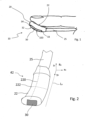
- Figure 1 and 4 depicts an exemplary ultrasound hand probe 10 according to the invention.
- the housing 20 comprises an elongated shape, as it can be seen on figure 2 .
- elongated shape it should be understood a shape with a dimension along an axis which is substantially bigger than the dimensions of the housing 20 along the other two axes.
- the dimension of the housing 20 along the y 0 axis on figure 2 is substantially longer than the width of the housing 20 along the xo axis and the height of the housing along the zo axis.
- the ultrasound hand probe 10 comprises a curved finger base 22.
- the curved finger base 22 is curved along the longitudinal axis L A of the ultrasound hand probe 10.
- the curved finger base 22 comprises a main curvature 220 which is oriented along the longitudinal axis L A of the ultrasound hand probe 10.
- curvature we refer to the curvature of an external surface of the curved finger base 22.
- the curved finger base has a curvature which is close to the curvature of the tip of a human finger along the main axis of said finger.
- the curved finger base 22 fits the shape of the fingertip of the physician. This characteristic makes the use of the finger hand probe 10 ergonomic. Since the curved base 22 fits the shape of the fingertip, the ultrasound is thus more stable on the tip of the finger than a regular straight hand probe.
- the curved finger base 22 has a radius of curvature comprised between 2 centimeters and 5 centimeters. This radius is the radius of the curvature along the longitudinal axis of the finger hand probe 10. This radius corresponds to the radius that can be observed on most of the fingertips of physicians. As a result, the curved finger base 22 is fitted to the shape of the finger, making the finger hand probe more convenient to use.
- the radius of curvature of the first curvature 220 of the curved finger base 22 is constant or substantially constant. In other words, the radius of curvature of the first curvature of the curved finger base 22 keeps the same curvature along its longitudinal axis.
- the radius of curvature of the first curvature 220 of the curved finger base 22 can vary along the longitudinal axis of the ultrasound hand probe L A .
- the radius of curvature is higher on a proximal end 23 of the housing 20 than it is on the distal end 24 of said housing 20.
- This characteristic adapts the shape of the housing to the shape of a fingertip, which has lower curvature on its proximal end than on its distal end.
- the curved finger base 22 comprises a second curvature 222.
- the second curvature 222 is comprised in a plane which is perpendicular to the plane comprising the first curvature 220.
- the second curvature 222 is perpendicular to first curvature 220.
- This second curvature makes it easier to interact with an accessory device which will be presented later.
- the second curvature 222 is advantageously doesn't present cutting edges. This is particularly good because if the housing is inserted in a sterile glove, it doesn't risk cutting it.
- the housing 20 has an oval transversal section.
- transversal section we refer to the section of the housing 20 in a plane which is perpendicular or substantially perpendicular to the longitudinal axis L A of the ultrasound finger probe 10.
- oval section we refer to an oval shape of said section.
- oval we refer to a shape which is in the same time round and elongated. The round parts of this section are placed on the sides of the section and the elongation of the shape is oriented along an axis perpendicular to the longitudinal axis L A pf the ultrasound hand probe 10.
- the housing 20 has an ellipse-shaped transversal section.
- ellipse-shaped section we refer to a section that has the shape of an ellipse, which means that contour of the section follows a curve that can be obtained by the intersection of a cone with an oblique plane that does not cut the base of the cone.
- the housing 20 has a length comprised between 0.5 centimeters and 5 centimeters. Preferably, the length of the housing 20 is comprised between 1 centimeter and 3 centimeters. More preferably, the housing 20 has a length comprised between 2 centimeters and 2.5 centimeters. These values of length are these which give the size of the housing 20 which is the most convenient to use.
- the housing 20 has a width comprised between 0.5 centimeters and 2 centimeters. Preferably, the width of the housing 20 is comprised between 0.7 centimeter and 1.5 centimeters. More preferably, the housing 20 has a length comprised between 0.8 centimeter and 1 centimeter. These values of length are these which give the size of the housing 20 which is the most convenient to use.
- the curved transducer 30 is integrated in the housing 20.
- integrated in the housing 20 we mean that the curved transducer 30 is completely inside the housing 20, or that the curved transducer doesn't protrude from the housing 20.
- the assembly of the housing 20 and the transducer 30 forms a single surface, which involves no cutting edges for the assembly.
- the housing 20 is manufactured by a process of injection molding. Injection molding is a convenient and cheap way of manufacturing the housing 20.
- the curved transducer 30 is integral to the housing 20.
- the housing 20 is glued to the curved transducer 30.
- the housing 20 is assembled with the curved transducer 30 by potting.
- the housing 20 is 3D printed or machined to the curved transducer 30 size.
- the curved ultrasound array transducer 30 is configured to emit and receive ultrasounds along the longitudinal axis L A of the ultrasound hand probe 30.
- the curved ultrasound array transducer 30 is a curved linear array ultrasound transducer.
- the ultrasound transducer 30 is configured to receive ultrasounds. More precisely, it receives all kinds of ultrasounds and in particular the reflections of the ultrasound pulses emitted by the transducer 30.
- the curved ultrasound transducer 30 products a signal which is translated to an image of the ultrasound received by the transducer. It is this signal that permits to visualize the tissues under the skin of the patient.
- the curved ultrasound transducer 30 comprises preferentially an elongated shape, as it can be seen on figure 1 .
- elongated shape it should be understood a shape with a dimension along an axis which is substantially bigger than the dimensions of the curved ultrasound transducer 30 along the other two axes.
- the dimension of the curved ultrasound transducer 30 along the yo axis on figure 2 is substantially longer than the width of the curved ultrasound transducer 30 along the xo axis and the height of the housing along the zo axis.
- the curved ultrasound transducer 30 is curved along the longitudinal axis L A of the ultrasound hand probe 10.
- the curved ultrasound transducer 30 comprises a main curvature 320 which is oriented along the longitudinal axis L A of the ultrasound hand probe 10.
- curvature we refer to the curvature of an external surface of the curved ultrasound transducer 30.
- the curved ultrasound transducer 30 has a curvature 320 which is close to the curvature of the tip of a human finger along the main axis of said finger.
- the curved ultrasound transducer 30 fits the shape of the fingertip of the physician. This characteristic makes the use of the finger hand probe 10 ergonomic. Since the curved base 22 fits the shape of the fingertip, the physician can press the curved ultrasound transducer 30 on the skin of a patient as if it were the tip of his own finger. Additionally, he can roll the curved transducer 30 on the surface of the skin of a patient in order to vary the orientation of the curved transducer 30.
- the curved ultrasound transducer 30 has a radius of curvature comprised between 2 centimeters and 5 centimeters. This radius is the radius of the curvature along the longitudinal axis of the finger hand probe 10. This radius corresponds to the radius that can be observed on most of the fingertips of physicians.
- the radius of curvature of the main curvature 320 of the curved ultrasound transducer 30 is constant or substantially constant. In other words, the radius of curvature of the main curvature 320 of the curved ultrasound transducer 30 keeps the same curvature along its longitudinal axis.
- the radius of curvature of the main curvature 320 of the curved ultrasound transducer 30 can vary along the longitudinal axis of the ultrasound hand probe L A .
- the radius of curvature is higher on a proximal end 33 of curved ultrasound transducer 30 than it is on the distal end 34 of said curved ultrasound transducer 30. This characteristic makes it easier to orientate said curved ultrasound transducer 30 for a physician.
- the curved ultrasound transducer 30 is integrated in the housing 20 of the ultrasound hand probe 10.
- an exterior surface of the curved ultrasound transducer is comprised in an exterior surface of the housing 20.
- the curved ultrasound transducer doesn't protrude from the housing 20.
- the curved transducer 30 comprises a contact surface 32.
- the contact surface 32 of the curved transducer 30 is configured to be placed in contact with the surface of the skin of a patient.
- the contact surface 32 of the curved transducer and the outer surface of the housing 20 forms a continuous surface.
- the housing 20 encompass all exterior surfaces of the curved transducer 30 but the contact surface 32.
- the curved ultrasound transducer 30 has length comprised between 10 and 30 mm
- the curved transducer 30 defines a field of view of the ultrasound hand probe 10.
- field of view of the ultrasound hand probe we mean the zone in which the transducer 30 sends ultrasound waves and from which the transducer 30 receives ultrasounds.
- the field of view of the ultrasound hand probe 30 is comprised in a plane which perpendicular to the contact surface 32.
- the field of view of the ultrasound hand probe 10 is comprised in a plane which comprises the longitudinal axis L A of the ultrasound hand probe 10.
- the curved ultrasound transducer 30 has a sectorial field of view.
- the angle between the lines forming the two sides of the sectoral field of view is comprised between 0.1 and 0.5 degrees. More preferably, the angle between the lines forming the two sides of the sectoral field of view is comprised between 0.2 and .0.4 degrees
- the curved ultrasound transducer 30 emits and receive sonic waves in the domain of ultrasound sonic waves.
- the wavelength of the sonic waves emitted and received is comprised between 10 and 30 MHz.
- This field of wave lengths is adapted to visualize tissues of the body in various depths. More preferably, the wavelength of the sonic waves emitted and received is comprised between 18 and 20 MHz.
- This field of wave lengths is particularly adapted to visualize the superficial layers of the human skin, and is very convenient to assist a physician during an injection procedure in said tissues. Particularly, it permits to visualize blood vessels in these tissues and to avoid it when injecting.
- the curved ultrasound transducer 30 is linked to at least one wire 25.
- the wire 25 powers the transducer by giving it electrical energy.
- the wire is also used to acquire the signal generated by the ultrasound curved transducer 30.
- the signal of the transducer 30 in response to the reception of ultrasounds can be transmitted by the wire to an external visualization device.
- the ultrasound hand probe 10 comprises at least one accessory device 40.
- the accessory device 40 comprises at least one first attach 41.
- the first attach 41 is configured to attach the accessory device 40 to the housing 20 of the ultrasound hand probe 10.
- the first attach 41 comprises a shape that can be clipped on the housing.
- the first attach 41 comprises a shape which is complementary to the shape of the housing 20.
- the first attach 41 forms a rail in which the housing 20 can be inserted.
- the rail is a good shape to easily fixed the housing 20 in the first attach.
- the first attach 41 comprises a clip.
- the clip is configured to fasten the housing 20 of the ultrasound hand probe to the accessory device 40.
- the clip 41 comprises at least one flexible part.
- the flexible part is able to deform when submitted to a strain. When inserting the housing 20 in the first attach 41, the flexible part is deformed and retract when the housing 20 is in its fastened position.
- the flexible part is deformed again until the housing 20 is free.
- the flexible part comprises two flexible parts.
- the two flexible parts form the clip.
- the two flexible parts act as a clamp maintaining the housing 20 fixed with the accessory device.
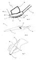
- FIG. 3 presents an accessory device according to an embodiment.
- the first attach 41 is in the shape of a rail in which the housing 20 can be inserted.
- the accessory device 40 comprises a finger clip 42.
- the finger clip 42 has a size adapted for a finger to be inserted in.
- the housing 20 is inserted in the first attach 41.
- the housing 20 and the curved transducer 30 are fixed to the accessory device 40.
- the physician inserts his finger, preferably the index finger, in the finger clip 42.
- the ultrasound hand probe 10 is attached to the finger of the physician. In this way, the physician has both hands free. This characteristic facilitates the injection procedure.
- the accessory device 40 comprises retaining wings 420.
- the accessory device 40 comprises two retaining wings 420.
- the two retaining wings 420 are placed on the sides of the accessory device.
- the retaining wings 420 act as a clamp for the finger of the physician.
- the accessory device 40 and the ultrasound hand probe are well maintained on the finger of the physician.
- the accessory device 40 comprises a finger hole.
- the finger hole has a radius adapted for the introduction of a finger inside it. As a result, the accessory device is fixed to the finger of the physician when said finger is inserted in the finger hole.
- Figure 4 represents the finger hand probe 10 and the accessory device 40 of figure 3 installed on the finger of a physician.
- the figure also represents a surface 50 of the skin of a patient.
- the curved transducer 30 is in contact with the surface of the skin 50 of the patient in order to scan said skin and subcutaneous tissues.
- the physician applies a force on the finger hand probe 10 in direction to the skin of the patient to scan said skin.
- the hand probe 10 applies a reciprocal force F 1 on the finger of the physician.
- this reciprocal force F 1 is inclined with respect to the main axis of the finger. That means that a large amount of the force is transmitted in alignment with the main axis of the finger.
- the reciprocal force F 1 tends to be perpendicular with the main axis of the finger, which implies a lot of strains and fatigue on the finger and its articulations.
- the finger hand probe 10 according to the invention provokes less fatigue to the physician than known devices, and facilitate the application of a force to the probe 10.
- the accessory device 40 comprises a rotating accessory fastener.
- the rotating accessory fastener is placed between the first attach 41 and the finger clip and/or retaining wings 420.
- the rotating accessory fastener allows a rotation between the first attach 41 and the rest of the accessory device 40.
- This rotation between the first attach 41 and the finger clip and/or retaining wings 420 is showed by the arrow on figure 3 , and the axis of rotation is showed on this figure by the vertical dotted line.
- the housing 20 and the curved ultrasound transducer 30 can rotate with respect to the finger of the physician when the accessory device 40 is fixed to the finger of the physician.
- the rotating accessory fastener comprises a return element.
- the return element applies a returning torque to the first attach 41 when it not in a resting position.
- the return element makes it rotate to come back in its initial position. This characteristic allows the physician to rotate his finger when the curved ultrasound transducer 30 is in contact with the skin of the patient without rotating the curved transducer 30, the curved ultrasound transducer coming back into place when it is no longer in contact with the skin of the patient.
- the rotating accessory fastener is also compatible with the embodiments of the accessory device 40 described below.
- the accessory device 40 has a general shape of a hockey stick.
- the accessory device 40 comprises a shaft 43.
- the first attach of the accessory device 40 is placed at an end of the shaft 43.
- the main axis of the hand probe 10 is angle regarding a main axis of the shaft 43.
- the housing 20 and the transducer 30 can be fastened to the end of the shaft.
- the hockey stick shape of the accessory device 40 permits the physician to hold the ultrasound hand probe 10 between two fingers while operating.
- the physician holds the shaft 443 between his index finger and his thumb.
- the hockey stick shape is a convenient shape for injection procedures since it allows the physician to apply a force on the skin of the patient.
- the accessory device 40 comprises a shaper forming "T".
- the "T" of the “T” shape is placed on top of the first attach 41.
- the "T” has a height which is close to the height of a finger.
- the physician places two of his fingers around the vertical bar of the "T”. As a result, the fingers are maintained between the lateral bar which is on top of the "T” and the first attach 41.
- the ultrasound hand probe 10 is fixed to the fingers of the physician, allowing him to manipulate the ultrasound hand probe 10 freely.
- FIG 6 and figure 7 represent an accessory device according to a fourth embodiment.
- the accessory device 40 comprises a finger hole 44.
- the finger hole 44 has a size adapted for a human finger to be inserted in.
- the finger hole 44 has a size adapted for the passage of an index finger.
- the accessory device 40 comprises a shaft 43.
- the shaft 43 is placed on top of the finger hole 44.
- the shaft 43 advantageously permits the user to manipulate the accessory device 40.
- the shaft 43 has the advantage of allowing a transmission of forces applied to the ultrasound hand probe 10 to the back of the hand of the user.
- the shaft 43 is optional and it is possible to have an accessory device 40 without the shaft 43.
- the accessory device 40 comprises an attach shaft 45.
- the attach shaft 45 comprises the first attach 41.
- the first attach 41 is a gutter.
- the gutter has a size adapted to receive the housing 20 and to maintain it on the accessory device 40.
- the housing 20 is inserted in the gutter to be fixed to the accessory device 40.
- the housing 20 and the curved ultrasound transducer 30 are placed in regards with the tip of the finger of the physician.
- F 1 force with his finger on the housing 20
- the force applied on the hand of the physician is then spread between the finger of the physician, the articulation linking the finger and the hand of the physician and the back of the hand of the physician. This results in less fatigue for the physician when he manipulates the probe.
- the accessory device 40 comprises a needle guide.
- a finger hand probe 10 comprising an accessory device 40 comprising the needle guide 47 is represented on figure 5 .
- This figure also represents a needle 49 inserted in the needle guide 47.
- the accessory devices 40 of all the embodiments described above can comprise a needle guide.
- the orientation of the needle guide may be adjustable respective to the main axis of the ultrasound probe 30, or the main axis of the housing 20.
- the orientation of the needle guide may be sensibly parallel to the main axis of the finger of the physician.
- the needle guide 47 is preferably placed at the distal end of the accessory device 40.
- the needle guide 47 comprises at least one needle hole 48 or at least one needle gutter.
- the needle hole 48 or gutter has a diameter and size which is adapted to the passage of a needle 49. Preferably, the diameter and size are adjusted to the size of the needle 49.
- the needle guide 47 forms a straight path that guides the needle when it is inserted inside the needle hole 48 or gutter.
- the needle guide 47 comprises an element protruding from the accessory device 40.
- the needle hole 48 or gutter passes through the protrusion of the needle guide 47. An end of the needle hole 48 or gutter comes in contact or near the skin surface of the patient when the curved ultrasound transducer 30 is in contact with the surface of the skin of the patient.
- the needle guide 47 is adapted to guide a needle 49 during an injection procedure.
- This characteristic facilitates the injection procedure.
- the accessory device 40 comprises one two, three or more needle guides or needle gutters. This characteristic enables to vary the sites where the needle penetrates the skin of the patient.
- the various needle guides or needle gutters can have different spatial orientations. This characteristic enables to guide a needle with different angles respective to the skin of the patient during the injection procedure.
- the needle guide 47 is rotatable with respect to a main part of the accessory device 40. This characteristic enables the physician to adjust the point of injection with respect to the ultrasound hand probe 10. This characteristic also permits adjusting the angle penetration of the needle in the skin of the patient.
- the housing 20 comprises at least one needle guide 47.
- the needle guide is preferably placed at the distal end of the housing 40.
- the needle guide 47 comprises at least one needle hole or at least one needle gutter.
- the needle hole 48 or gutter has a diameter and size which is adapted to the passage of a needle 49. Preferably, the diameter and size are adjusted to the size of the needle.
- the needle guide 47 forms a straight path that guides the needle when it is inserted inside the needle hole or gutter.
- the needle guide 47 comprises an element protruding from the housing 20.
- the needle hole 48 or gutter passes through the protrusion of the needle guide 47.
- the needle guide 47 is adapted to guide a needle during an injection procedure.
- the housing 20 comprises one two, three or more needle holes 48 or needle gutters. This characteristic enables to vary the sites where the needle penetrates the skin of the patient.
- the various needle guides or needle gutters can have different spatial orientations. This characteristic enables to guide a needle with different angles respective to the skin of the patient during the injection procedure.
- the needle guide of the housing 20 is rotatable with respect to a main part of the housing 20. This characteristic enables the physician to adjust the point of injection with respect to the ultrasound hand probe 10.
- the ultrasound hand probe 10 is linked to a visualizing device.
- the visualizing device is configured to display on a screen the image representing the subcutaneous tissues of the patient.
- the image is obtained from the ultrasound signal acquired by the ultrasound curved transducer 30.
- the image displayed on the visualizing device permits the physician to be assisted during the injection procedure and to avoid blood vessels during the injection procedure. This makes the procedure safer for the patient.
- the housing 20 comprises electrical wires for supplying electrical energy to the curved transducer 30.
- the housing 20 comprises a battery that supplies electrical energy to the ultrasound curved transducer 30.
- the housing 20 comprises at least one electrical wire configured to transmit a signal acquired by the ultrasound curved transducer 30.
- the signal of the ultrasound curved transducer 30 is an image of the tissues scanned by the ultrasound hand probe 10.
- the ultrasound hand probe 10 is configured to transmit the signal produced by the ultrasound curved transducer 30 wirelessly.
- the wireless configuration of the ultrasound hand probe 10 permits to free the movements of the physician when he manipulates the probe 10, since there is no wire.
- the signal is transferred via a radio frequency communication.
- the signal is transferred via a Wi-Fi connection or a Bluetooth ® connection.
- the invention also concern method for injecting a substance and/or a medical device under the skin of a patient.
- the substance injected can be a fluid like a treatment fluid.
- This substance can also be any possible filler, no matter if the filler is in a fluid or gel form or any other form.
- the method also concerns the injection of any medical device under the skin, for example the placement of a thread.
- the method for injecting a substance and/or a medical device is realized with the ultrasound hand probe according to the invention.
Landscapes
- Health & Medical Sciences (AREA)
- Life Sciences & Earth Sciences (AREA)
- Engineering & Computer Science (AREA)
- Heart & Thoracic Surgery (AREA)
- Public Health (AREA)
- Biophysics (AREA)
- Veterinary Medicine (AREA)
- Pathology (AREA)
- Physics & Mathematics (AREA)
- Biomedical Technology (AREA)
- General Health & Medical Sciences (AREA)
- Medical Informatics (AREA)
- Molecular Biology (AREA)
- Surgery (AREA)
- Animal Behavior & Ethology (AREA)
- Radiology & Medical Imaging (AREA)
- Nuclear Medicine, Radiotherapy & Molecular Imaging (AREA)
- Computer Networks & Wireless Communication (AREA)
- Vascular Medicine (AREA)
- Ultra Sonic Daignosis Equipment (AREA)
Priority Applications (9)
| Application Number | Priority Date | Filing Date | Title |
|---|---|---|---|
| EP21315138.4A EP4137060A1 (en) | 2021-08-17 | 2021-08-17 | Curved ultrasound probe |
| EP22762113.3A EP4387529A1 (en) | 2021-08-17 | 2022-08-17 | Curved ultrasound probe |
| KR1020247008895A KR20240046571A (ko) | 2021-08-17 | 2022-08-17 | 곡면형 초음파 프로브 |
| AU2022331798A AU2022331798A1 (en) | 2021-08-17 | 2022-08-17 | Curved ultrasound probe |
| JP2024510532A JP2024531429A (ja) | 2021-08-17 | 2022-08-17 | 湾曲した超音波プローブ |
| CN202280070049.7A CN118119343A (zh) | 2021-08-17 | 2022-08-17 | 弯曲超声探头 |
| CA3229348A CA3229348A1 (en) | 2021-08-17 | 2022-08-17 | Curved ultrasound probe |
| US18/684,726 US12648735B2 (en) | 2021-08-17 | 2022-08-17 | Curved ultrasound probe |
| PCT/EP2022/073002 WO2023021110A1 (en) | 2021-08-17 | 2022-08-17 | Curved ultrasound probe |
Applications Claiming Priority (1)
| Application Number | Priority Date | Filing Date | Title |
|---|---|---|---|
| EP21315138.4A EP4137060A1 (en) | 2021-08-17 | 2021-08-17 | Curved ultrasound probe |
Publications (1)
| Publication Number | Publication Date |
|---|---|
| EP4137060A1 true EP4137060A1 (en) | 2023-02-22 |
Family
ID=77710716
Family Applications (2)
| Application Number | Title | Priority Date | Filing Date |
|---|---|---|---|
| EP21315138.4A Withdrawn EP4137060A1 (en) | 2021-08-17 | 2021-08-17 | Curved ultrasound probe |
| EP22762113.3A Pending EP4387529A1 (en) | 2021-08-17 | 2022-08-17 | Curved ultrasound probe |
Family Applications After (1)
| Application Number | Title | Priority Date | Filing Date |
|---|---|---|---|
| EP22762113.3A Pending EP4387529A1 (en) | 2021-08-17 | 2022-08-17 | Curved ultrasound probe |
Country Status (8)
| Country | Link |
|---|---|
| US (1) | US12648735B2 (enExample) |
| EP (2) | EP4137060A1 (enExample) |
| JP (1) | JP2024531429A (enExample) |
| KR (1) | KR20240046571A (enExample) |
| CN (1) | CN118119343A (enExample) |
| AU (1) | AU2022331798A1 (enExample) |
| CA (1) | CA3229348A1 (enExample) |
| WO (1) | WO2023021110A1 (enExample) |
Cited By (1)
| Publication number | Priority date | Publication date | Assignee | Title |
|---|---|---|---|---|
| EP4678113A1 (en) * | 2024-07-08 | 2026-01-14 | Thinkin Tech | Curved ultrasound fingertip probe |
Families Citing this family (2)
| Publication number | Priority date | Publication date | Assignee | Title |
|---|---|---|---|---|
| US12507988B2 (en) * | 2022-01-27 | 2025-12-30 | Oregon Health & Science University | Transducer fixation apparatus |
| US12599363B2 (en) * | 2024-04-24 | 2026-04-14 | GE Precision Healthcare LLC | Wearable device for hands-free operation of an ultrasound probe |
Citations (6)
| Publication number | Priority date | Publication date | Assignee | Title |
|---|---|---|---|---|
| US5598846A (en) * | 1995-12-21 | 1997-02-04 | Hewlett-Packard Company | Rotatable ultrasound transducer finger probe |
| US20050085731A1 (en) * | 2003-10-21 | 2005-04-21 | Miller David G. | Ultrasound transducer finger probe |
| US20050096554A1 (en) * | 2002-11-27 | 2005-05-05 | Dudik Evan M. | Acoustic medical sensor for ultrasound imaging |
| US20080300488A1 (en) * | 2002-11-27 | 2008-12-04 | Schutz Ronald W | Finger mounted probe adapted for intraoperative use |
| US20090163807A1 (en) * | 2007-12-21 | 2009-06-25 | Sliwa John W | Finger-mounted or robot-mounted transducer device |
| US20130150725A1 (en) * | 2011-12-13 | 2013-06-13 | Samsung Electronics Co., Ltd. | Probe for ultrasonic diagnostic apparatus |
Family Cites Families (14)
| Publication number | Priority date | Publication date | Assignee | Title |
|---|---|---|---|---|
| US5284147A (en) * | 1989-05-22 | 1994-02-08 | Hitachi Medical Corporation | Ultrasonic probe to be installed on fingertip |
| JP2768984B2 (ja) * | 1989-07-21 | 1998-06-25 | 株式会社日立メディコ | 超音波探触子 |
| US5152293A (en) * | 1991-07-01 | 1992-10-06 | Northwestern University | Finger-mounted intraoperative imaging device |
| US5752517A (en) * | 1996-10-18 | 1998-05-19 | Advanced Technology Laboratories, Inc. | Intraoperative ultrasound probes for ultrasonic examination during surgery |
| US5895871A (en) * | 1997-07-25 | 1999-04-20 | General Electric Company | Finger controlled inspection apparatus |
| JP3852183B2 (ja) * | 1997-09-30 | 2006-11-29 | フジノン株式会社 | 超音波プローブ |
| JP2000083953A (ja) * | 1998-09-08 | 2000-03-28 | Honda Electronic Co Ltd | 超音波診断装置のプローブ |
| US20040225217A1 (en) * | 2003-02-14 | 2004-11-11 | Voegele James W. | Fingertip ultrasound medical instrument |
| WO2010073913A1 (ja) * | 2008-12-26 | 2010-07-01 | コニカミノルタセンシング株式会社 | 生体情報測定用プローブ |
| US9649092B2 (en) * | 2012-10-12 | 2017-05-16 | Muffin Incorporated | Devices and methods for three-dimensional internal ultrasound usage |
| US9205258B2 (en) * | 2013-11-04 | 2015-12-08 | ElectroCore, LLC | Nerve stimulator system |
| US20190125064A1 (en) * | 2017-10-27 | 2019-05-02 | Butterfly Network, Inc. | Holster for ultrasound imaging device |
| US20190254626A1 (en) | 2018-02-22 | 2019-08-22 | Sonivate Medical, Inc. | Graphical user interface for ultrasound system |
| IL298685B2 (en) * | 2020-03-05 | 2024-08-01 | Exo Imaging Inc | An ultrasound imaging device with programmable anatomy and flow imaging |
-
2021
- 2021-08-17 EP EP21315138.4A patent/EP4137060A1/en not_active Withdrawn
-
2022
- 2022-08-17 EP EP22762113.3A patent/EP4387529A1/en active Pending
- 2022-08-17 CA CA3229348A patent/CA3229348A1/en active Pending
- 2022-08-17 WO PCT/EP2022/073002 patent/WO2023021110A1/en not_active Ceased
- 2022-08-17 CN CN202280070049.7A patent/CN118119343A/zh active Pending
- 2022-08-17 AU AU2022331798A patent/AU2022331798A1/en active Pending
- 2022-08-17 KR KR1020247008895A patent/KR20240046571A/ko active Pending
- 2022-08-17 JP JP2024510532A patent/JP2024531429A/ja active Pending
- 2022-08-17 US US18/684,726 patent/US12648735B2/en active Active
Patent Citations (6)
| Publication number | Priority date | Publication date | Assignee | Title |
|---|---|---|---|---|
| US5598846A (en) * | 1995-12-21 | 1997-02-04 | Hewlett-Packard Company | Rotatable ultrasound transducer finger probe |
| US20050096554A1 (en) * | 2002-11-27 | 2005-05-05 | Dudik Evan M. | Acoustic medical sensor for ultrasound imaging |
| US20080300488A1 (en) * | 2002-11-27 | 2008-12-04 | Schutz Ronald W | Finger mounted probe adapted for intraoperative use |
| US20050085731A1 (en) * | 2003-10-21 | 2005-04-21 | Miller David G. | Ultrasound transducer finger probe |
| US20090163807A1 (en) * | 2007-12-21 | 2009-06-25 | Sliwa John W | Finger-mounted or robot-mounted transducer device |
| US20130150725A1 (en) * | 2011-12-13 | 2013-06-13 | Samsung Electronics Co., Ltd. | Probe for ultrasonic diagnostic apparatus |
Cited By (2)
| Publication number | Priority date | Publication date | Assignee | Title |
|---|---|---|---|---|
| EP4678113A1 (en) * | 2024-07-08 | 2026-01-14 | Thinkin Tech | Curved ultrasound fingertip probe |
| WO2026013089A1 (en) * | 2024-07-08 | 2026-01-15 | Thinkin Tech | Curved ultrasound fingertip probe |
Also Published As
| Publication number | Publication date |
|---|---|
| US20240350085A1 (en) | 2024-10-24 |
| CA3229348A1 (en) | 2023-02-23 |
| JP2024531429A (ja) | 2024-08-29 |
| AU2022331798A1 (en) | 2024-03-28 |
| US12648735B2 (en) | 2026-06-09 |
| CN118119343A (zh) | 2024-05-31 |
| KR20240046571A (ko) | 2024-04-09 |
| WO2023021110A1 (en) | 2023-02-23 |
| EP4387529A1 (en) | 2024-06-26 |
Similar Documents
| Publication | Publication Date | Title |
|---|---|---|
| JP7173205B2 (ja) | 穿刺ガイド、及び穿刺ガイド付き超音波診断装置 | |
| US20240350085A1 (en) | Curved ultrasound probe | |
| US6139502A (en) | Ultrasonic transducer probe and handle housing and stand-off pad | |
| US20220039829A1 (en) | Vascoscope | |
| US20200305927A1 (en) | Biopsy systems, ultrasound devices, and methods of use thereof | |
| US20110105908A1 (en) | Finger mounted imaging probe and skin broaching assembly | |
| CA3215523A1 (en) | A portable ultrasound device and method for ultrasonic imaging | |
| US4582066A (en) | Ultrasonic transducer probe | |
| WO2018200781A1 (en) | Multi-transducer ultrasonic tool-guidance | |
| WO2011085135A1 (en) | Blood vessel access device, sysem, and method | |
| US20140288427A1 (en) | Devices and methods for tissue navigation | |
| EP4609799A2 (en) | Ultrasound finger probe and methods thereof | |
| WO2010085662A2 (en) | Ultrasonic probe device and system and methods of generating ultrasonic images | |
| WO2020238561A1 (zh) | 一种实时高分辨穿刺引导系统 | |
| CA1326192C (en) | Apparatus for use in cannulation of blood vessels | |
| US6036645A (en) | Ultrasonic probe | |
| KR101893640B1 (ko) | 십자형 또는 t자형 초음파 프로브 및 이를 이용한 초음파 진단장치 | |
| CN219184014U (zh) | 一种可调节经静脉肝内穿刺装置 | |
| WO2024196876A2 (en) | Ultrasound imaging multi-array probe apparatus and system | |
| JP4005843B2 (ja) | 超音波探触子 | |
| CN117398122A (zh) | 一种超声诊疗设备及控制方法 | |
| JP4616750B2 (ja) | 超音波探触子 | |
| CN209404813U (zh) | 超声探头组件 | |
| EP1357837A1 (en) | Apparatus and method for determining the possible allowable needle size | |
| US20230389632A1 (en) | Ultrasound Probe Hand Shield |
Legal Events
| Date | Code | Title | Description |
|---|---|---|---|
| PUAI | Public reference made under article 153(3) epc to a published international application that has entered the european phase |
Free format text: ORIGINAL CODE: 0009012 |
|
| STAA | Information on the status of an ep patent application or granted ep patent |
Free format text: STATUS: THE APPLICATION HAS BEEN PUBLISHED |
|
| AK | Designated contracting states |
Kind code of ref document: A1 Designated state(s): AL AT BE BG CH CY CZ DE DK EE ES FI FR GB GR HR HU IE IS IT LI LT LU LV MC MK MT NL NO PL PT RO RS SE SI SK SM TR |
|
| STAA | Information on the status of an ep patent application or granted ep patent |
Free format text: STATUS: THE APPLICATION IS DEEMED TO BE WITHDRAWN |
|
| 18D | Application deemed to be withdrawn |
Effective date: 20230823 |