EP4137008B1 - Verbesserte schaukelbeine für ein bett - Google Patents
Verbesserte schaukelbeine für ein bett Download PDFInfo
- Publication number
- EP4137008B1 EP4137008B1 EP22187943.0A EP22187943A EP4137008B1 EP 4137008 B1 EP4137008 B1 EP 4137008B1 EP 22187943 A EP22187943 A EP 22187943A EP 4137008 B1 EP4137008 B1 EP 4137008B1
- Authority
- EP
- European Patent Office
- Prior art keywords
- motion
- leg
- motion imparting
- imparting
- legs
- Prior art date
- Legal status (The legal status is an assumption and is not a legal conclusion. Google has not performed a legal analysis and makes no representation as to the accuracy of the status listed.)
- Active
Links
Images

Classifications
-
- A—HUMAN NECESSITIES
- A47—FURNITURE; DOMESTIC ARTICLES OR APPLIANCES; COFFEE MILLS; SPICE MILLS; SUCTION CLEANERS IN GENERAL
- A47C—CHAIRS; SOFAS; BEDS
- A47C21/00—Attachments for beds, e.g. sheet holders or bed-cover holders; Ventilating, cooling or heating means in connection with bedsteads or mattresses
- A47C21/006—Oscillating, balancing or vibrating mechanisms connected to the bedstead
-
- A—HUMAN NECESSITIES
- A47—FURNITURE; DOMESTIC ARTICLES OR APPLIANCES; COFFEE MILLS; SPICE MILLS; SUCTION CLEANERS IN GENERAL
- A47C—CHAIRS; SOFAS; BEDS
- A47C19/00—Bedsteads
- A47C19/02—Parts or details of bedsteads not fully covered in a single one of the following subgroups, e.g. bed rails, post rails
- A47C19/021—Bedstead frames
- A47C19/024—Legs
-
- A—HUMAN NECESSITIES
- A47—FURNITURE; DOMESTIC ARTICLES OR APPLIANCES; COFFEE MILLS; SPICE MILLS; SUCTION CLEANERS IN GENERAL
- A47C—CHAIRS; SOFAS; BEDS
- A47C17/00—Sofas; Couches; Beds
-
- A—HUMAN NECESSITIES
- A47—FURNITURE; DOMESTIC ARTICLES OR APPLIANCES; COFFEE MILLS; SPICE MILLS; SUCTION CLEANERS IN GENERAL
- A47C—CHAIRS; SOFAS; BEDS
- A47C17/00—Sofas; Couches; Beds
- A47C17/86—Parts or details specially adapted for beds, sofas or couches not fully covered by any single one of groups A47C17/02 - A47C17/84
-
- A—HUMAN NECESSITIES
- A47—FURNITURE; DOMESTIC ARTICLES OR APPLIANCES; COFFEE MILLS; SPICE MILLS; SUCTION CLEANERS IN GENERAL
- A47C—CHAIRS; SOFAS; BEDS
- A47C19/00—Bedsteads
- A47C19/22—Combinations of bedsteads with other furniture or with accessories, e.g. with bedside cabinets
-
- A—HUMAN NECESSITIES
- A47—FURNITURE; DOMESTIC ARTICLES OR APPLIANCES; COFFEE MILLS; SPICE MILLS; SUCTION CLEANERS IN GENERAL
- A47D—FURNITURE SPECIALLY ADAPTED FOR CHILDREN
- A47D9/00—Cradles ; Bassinets
- A47D9/02—Cradles ; Bassinets with rocking mechanisms
- A47D9/04—Cradles ; Bassinets with rocking mechanisms with disconnectable rockers
-
- H—ELECTRICITY
- H02—GENERATION; CONVERSION OR DISTRIBUTION OF ELECTRIC POWER
- H02K—DYNAMO-ELECTRIC MACHINES
- H02K41/00—Propulsion systems in which a rigid body is moved along a path due to dynamo-electric interaction between the body and a magnetic field travelling along the path
- H02K41/02—Linear motors; Sectional motors
- H02K41/025—Asynchronous motors
Definitions
- the present invention relates to improved rocking legs for a bed and particularly to improved rocking legs which impart an oscillatory or reciprocal movement in a horizontal plane.
- each motion imparting leg comprises an electric motor used to drive a moving block on sliding bars which is connected to the bed through a bracket or similar.
- the moving block is suspended above the electric motor with both being connected through either a worm gear reducer or timing pulley gear reducer, the reducers being used to reduce the speed of the motor while increasing torque.
- the mechanical reducers add sources of noise and vibration, especially if not maintained correctly, which may mean that the rocking bed user is unable to fall asleep or will have their sleep disturbed.
- a motion imparting leg for imparting an oscillating or reciprocating rectilinear motion to a rocking bed, the leg comprising a base, an upper surface spaced from the base and rectilinearly movable relative to the base for imparting the oscillating or reciprocating motion to the rocking bed, a servo motor for driving movement of the upper surface, a position sensing means for determining the rotational position of the servo motor or the position of the upper surface, and a motor controller configured to use field-oriented control to control the servo motor based on data from the position sensing means.
- the use of a servo motor controlled through a position sensing means is highly advantageous because it can operate at low speeds with high torque with reduced audible noise and vibration. It also has the added advantages of reducing maintenance requirements and increasing reliability because there are no worm gear or pulley reducers.
- the motion inducing legs may be considered rocking legs or rocker legs.
- a position sensing means advantageously may not rely on back electro motive force (EMF) to estimate position. This is particularly advantageous as back EMF is not strong at low rotational speeds.
- EMF back electro motive force
- Low speed may be considered to have an rpm of 180 or below. That is to say the servo motor may be controlled to have a maximum motor speed of 180 rpm. A preferable maximum motor speed during normal use may be 100 rpm or less.
- the motor speed is controllable to a desired user speed between a range of speeds.
- the speed of the servo motor is controlled between the ends of the rectilinear motion path.
- the speed of the servo motor may change during the motion path.
- a S-shaped ramp may be used to control the servo motor speed. This allows for the servo motor to slow down and stop towards the ends of the motion path before changing direction which produces a smoother oscillating or reciprocating rectilinear motion.
- a high torque may be considered enough force to move an average bed and occupant.
- each of the servo motors may generate sufficiently high torque with approximately 700mA.
- Rectilinear motion may be considered translational motion back and fore in a horizontal plane.
- a motion imparting leg may be provided without a worm gear reducer or pulley reducers.
- a motion imparting leg may be provided without a worm gear reducer or pulley reducer coupled to motor shaft.
- the servo motor may be a brushless motor.
- the servo motor may be a brushed motor.
- the servo motor may be a DC servo motor.
- the position sensing means may include a rotary encoder disposed to the rotor or shaft of the servo motor.
- the rotary encoder may be an optical or magnetic encoder.
- the rotary encoder advantageously provides precise positioning for the low speed and high torque application of the electric motor.
- the position sensing means may include a linear encoder for encoding the position of the upper surface.
- a linear encoder either individually or in combination with other means such as the rotary encoder, provides precise positioning for the low speed and high torque application. It has the added advantage of improving synchronicity between multiple motion imparting legs.
- a rectilinear motion assembly may be provided for converting the rotation of the motor shaft to linear movement of the upper surface.
- the rectilinear motion assembly may comprise a threaded rod, such as a leadscrew rod, rotationally coupled to the shaft of the servo motor.
- the threaded rod may be coupled to the upper surface.
- the end of the threaded rod may be coupled to the end of motor shaft.
- the motion imparting leg may be provided without a worm gear reducer or pulley reducer coupling the rectilinear motion assembly to the shaft of the servo motor.
- the end of the threaded rod may be aligned with the end of the shaft of the servo motor.
- the threaded rod may be aligned on substantially the same axis as the shaft of the servo motor. That is to say that the threaded rod and shaft of the servo motor may be concentric.
- the height of the motion imparting leg is reduced by aligning the end of the threaded rod and motor shaft so that they are disposed on substantially the same axis, i.e. concentric.
- a further advantage is that a motion imparting leg with reduced height is more stable since it is more difficult to tip over.
- a flexible shaft coupling may be provided.
- the flexible coupling may couple an end of the threaded rod to an end of the servo motor shaft.
- the flexible couple may provide a means to address angular misalignment, eccentricity, and or axial misalignment. That is to say, the flexible shaft coupling may provide a means to address angular misalignment, eccentricity, and/or axial misalignment.
- the flexible shaft coupling allows for a deviation in the alignment between the threaded rod and motor shaft which reduces the manufacturing burden as perfect alignment is not needed. It has the added advantage of improving reliability as the alignment between rod and shaft may drift over time.
- the rectilinear motion assembly may comprise a movable carriage.
- the movable carriage may be movably disposed on the threaded rod.
- the movable carriage may be coupled to the upper surface.
- the upper surface may be provided in the movable carriage.
- the movable carriage may comprise a threaded aperture in which the threaded rod is received.
- the movable carriage may comprise a linear slider assembly.
- the linear slider assembly may be disposed parallel to the threaded rod.
- the linear slider assembly may comprise a first slider element coupled to the movable carriage and a second slider element disposed to the base.
- the second slider element being a guide rail and the first slider element being a movable block which is received on the guide rail.
- the second slider element is mounted to the base. More preferably the second slider element is mounted to a surface of the base opposite a ground bearing surface.
- the linear slider assembly supports the movable carriage as well as ensuring that the weight from the bed is transferred to the base of the motion imparting leg. This allows the motion imparting leg to support heavier beds, as each leg can support more weight. For example, the motion imparting leg may support up to 1000 kilograms. A further advantage is that the reduced height of the leg increases stability as it is more difficult to tip over.
- the linear slider assembly may also be called a linear bearing assembly.
- the linear encoder may be disposed to a component of the motion imparting leg which undergoes rectilinear movement.
- the linear encoder may be disposed to the linear slider assembly.
- the linear encoder may be disposed to the movable carriage.
- the linear encoder may be disposed to the upper surface.
- the motor controller may be configured to use variable-frequency drive control.
- the motor controller may be configured to use field-oriented control, also known as vector control.
- Control strategies such as field field-oriented control, allow for the torque, speed and/or position of the servo motor to be controlled based on the position sensing means. That is to say at least one of the torque, speed and position of the servo motor may be controlled based on the position sensing means.
- the motor controller using field-oriented control may determine the required current to be injected into the motor coils in real time. That is to say that calculations may be performed 20000 times per second. This allows the current to be more precisely controlled than in standard motors which reduces power consumption.
- field-oriented control provides for reduced power loss through inefficiencies, such as vibration or heat. Furthermore, the power consumption of the motion imparting leg is reduced.
- the motor controller may use the data from the position sensing means to determine the position of the motor. The motor controller may control the motor based on a comparison between the determined position of the motor and a desired motion or position path. The desired motion or position path may be received from a central control hub.
- the motor controller may store positional data in a persistent memory, such as FLASH or EEPROM, when the motor stop rotating, for example during normal shutdown.
- the positional data may be indicative of the position of the rotatory encoder.
- the positional data may be indicative of the position of the linear encoder.
- the motor controller upon start up, may retrieve the positional data stored in the persistent memory.
- Storing this data in the persistent memory means that there is no need to determine the ends of the upper surface motion path, that is to say there is no need to recalibrate the position of the upper surface of the extent or length of the motion path.
- the motor controller may be configured to inject current through the motor stator windings in an iterative process to determine the relative motor rotor position, against the motor stator windings.
- the instantaneous rotor stator relative position i.e. the initial rotor position at startup relative to the stator, without positional data from the position sensing means such as the rotary encoder. This ensures that the electric motor may operate from start up because the electrical currents injected into the motor windings during normal operation use phases that are derived from the instantaneous rotor stator relative position.
- the motor controller may comprise a communication means for receiving and/or transmitting data to a central control hub or to a same or similar motion imparting leg.
- the communication means allows data and information to be shared. This allows the motion between multiple motion imparting legs to be synchronised.
- the communication means may include a wired communication means.
- the communication means may include a wireless communication means.
- the motor controller may be configured to a maximum current limit.
- the motor controller may be configured to a limit of a predetermined amperage based on expected loads. For example, the motor controller may be configured to a limit of 2 amps.
- the motor controller may comprise a fixed-point processor.
- the motor controller may be configured to use fixed point data.
- this allows for reduced power consumption and reduced memory requirements. Furthermore, this allows for reduced cost.
- the base and upper surface are substantially parallel.
- the upper surface may be spaced from the base.
- a bed mounting bracket may be provided.
- the bed mounting bracket may be removably coupled to the upper surface.
- the bed mounting bracket may couple the motion imparting leg to a bed frame or bed leg of the rocking bed.
- a bed coupling means may be provided in the bed mounting bracket.
- the bed coupling means may provide a coupling means used to couple to a standard bed frame or beg legs, for example, screw apertures may be provided for coupling to a solid wooden bed frame or leg.
- clamps, grips or similar may be provided for coupling to a metal bed frame or leg, especially hollow bed frames or legs.
- a movable shroud may be provided.
- the movable shroud may substantially surround at least some of the components of the motion imparting leg.
- the upper surface may be provided in the movable shroud, that is the say the upper surface may be a face of the movable shroud.
- a safety system may be provided.
- the safety system may be configured to monitor for unexpected operation of the motion imparting leg.
- the safety system may be configured to generate a warning signal based on the motion imparting leg operating unexpectedly.
- the warning signal may be transmitted to a central control hub.
- the safety system may be provided in the motion imparting leg.
- the motor controller may comprise the safety system.
- the safety system may be configured to monitor for a decoupling between the motion of the electric motor and upper surface.
- the safety system may be configured to generate a decoupling warning signal as a result of determining a decoupling between the motion of the electric motor and upper surface.
- the decoupling warning signal may be used to shut down the motion imparting leg.
- Decoupling may be indicated by a difference between the expected position of the upper surface and the actual position of the upper surface. This may be as a result of a complete decoupling where there is no rectilinear motion despite rotation of the motor or a partial decoupling where there is some rectilinear motion but not as much as expected.
- the decoupling determination may be based on data from the position sensing means.
- the decoupling determination may be based on data from the rotary encoder and/or the linear encoder.
- the decoupling determination may be based on a monitored motor current and data from the rotary encoder.
- the safety system may be configured to monitor for excessive rectilinear motion. That is to say the safety system may be configured to monitor for rectilinear motion outside of a motion path length.
- the safety system may be configured to generate an excessive rectilinear motion warning signal as a result of determining excessive rectilinear motion of the upper surface or other rectilinearly moving component(s).
- the excessive rectilinear motion warning signal may be used to shut down the motion imparting leg.
- the excessive rectilinear motion determination may be based on data from sensors.
- the excessive rectilinear motion determination may be based on switches.
- the safety system may comprise at least two switches for determining excessive rectilinear motion.
- the switches preferably being optical switches.
- Each switch corresponds with a trigger means, such as a flange, blade or similar, for actuating the switch.
- the trigger means may be configured to interrupt a light path of the optical switch.
- Each switch may be disposed toward an end of a motion path of a rectilinearly moving component, such as the upper surface, movable carriage, slider assembly etc.
- Each optical switch may be disposed proximate an end of the second slider element.
- the switches may be considered stationary switches because they are in a fixed position relative to the rectilinearly moving component.
- Each trigger means may be disposed on a rectilinearly moving component, such as the upper surface, movable carriage, slider assembly etc.
- a blade or flange extends from each end of the first slider element.
- the trigger means may be considered a movable trigger means because it moves with a rectilinearly moving component.
- each switch may be disposed on a rectilinearly moving component, such as the upper surface, movable carriage, slider assembly etc.
- each optical switch may be disposed to an end of the first slider element.
- the switches may be considered movable switches because they move with a rectilinearly moving component.
- each trigger means may be disposed toward an end of a motion path of the rectilinearly moving component.
- a blade or flange is disposed proximate each end of the second slider element and extends into the path of the movable switch.
- the trigger means may be considered a stationary trigger means because they are in a fixed position relative to a moving component.
- At least one of the switches may be disposed to the same side as the motor controller. That is to say that at least one switch may be proximate the motor controller. This reduces the length of connection wires.
- the components moving rectilinearly (such as the upper surface, the slider assembly, the movable carriage etc) are restrained to move between two predetermined points during normal operation. Excessive rectilinear motion may be considered to occur when the components moving rectilinearly move past the predetermined points.
- the predetermined points being set before the motion imparting legs are supplied to a user.
- the switches may be positioned so that they are only actuated once the component moves past the predetermined points. That is to say the switches are not actuated during normal operation of the motion imparting leg.
- a safety system is beneficial as it may detect problems early which prevents the device from being further damaged.
- An emergency power supply system may be provided.
- the emergency power supply system may be configured to supply power to the motion imparting leg if there is a loss of power supplied by a main connection or central control hub.
- the emergency power supply system may supply power for a short temporary period, the short temporary period being sufficient for the motor controller to store positional data, and/or other data, in a persistent memory.
- the emergency power supply may include an energy store, such as a capacitor or battery.
- the energy store may be provided in the motion imparting leg and/or the central control hub.
- the emergency power supply system may include circuitry provided in the motor controller.
- the emergency power supply system may include circuitry provided in the central control hub.
- the emergency power supply advantageously provides sufficient power for relevant data to be stored in a memory if there is a loss of power.
- the relevant data may be positional data such as the position of the motor and/or the position of the upper surface or another component which is indicative of the upper surface position. This ensures that the motion imparting leg will have accurate positional information when operational power is supplied.
- Another aspect of the present invention may be provided by a motion imparting system, the system comprising a plurality of motion imparting legs.
- the motion imparting legs may be according to any other aspects of the present invention.
- the system may comprise a central control hub.
- the central control hub may be connectable to each motion imparting leg.
- the central control hub may include a communication means.
- the communication means may be wired and/or wireless.
- the central control hub may synchronise the rectilinear motion of the motion imparting legs.
- the central control hub may supply power to each motion imparting leg, in such cases it could be a central control and power hub.
- the central control hub may generate a desired motion or position path which is communicated to each motion imparting leg.
- each motion imparting leg comprises a safety system
- the central control hub may generate a shutdown signal upon receipt of a warning signal from at least one motion imparting leg.
- the shutdown signal may be communicated to each motion imparting leg.
- kits of parts for retrofitting to a bed comprising a plurality of motion imparting legs.
- the motion imparting legs may be according to any other aspect of the present invention.
- a central control hub connectable to each motion imparting leg may be provided in the kit of parts.
- the central control hub may comprise the same features as set out above.
- a rocking bed comprising a plurality of motion imparting legs fixedly attached to a bed frame.
- the motion imparting legs may be according to any other aspect of the present invention.
- a prefabricated rocking bed with motion imparting legs removes the complexity of retrofitting the motion imparting legs to an existing bed.
- a motion imparting leg for imparting an oscillating or reciprocating rocking motion in a horizontal plane to a rocking bed, comprising a base and an upper surface movable relative to the base, the movement being driven by a servo motor controlled by a position encoder attached to the rotor of the motor.
- a method of calibrating a motion imparting leg comprising an upper surface movable relative to a base through a motion path, an electric motor for driving movement of the upper surface through the motion path, a motor controller for controlling the electric motor and a positioning system, the method comprising the steps of operating the electric motor to drive the upper surface through the motion path until the positioning system determines both ends of the motion path, and storing the positional data related to both ends in the motor controller.
- the motion imparting leg in this method may be the motion imparting leg of any other aspect.
- This is advantageous as it determines the position of the upper surface and extent, or length, of the motion path, which is especially useful for newly manufactured motion imparting legs.
- This method also allows for existing motion imparting legs to be calibrated when needed.
- the positioning system may be the safety system described above, preferably the safety system which is configured to monitor for excessive rectilinear motion.
- the positioning system in this aspect may comprise two optical switches.
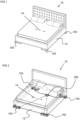
- a rocking bed is generally indicated at 10.
- motion imparting legs 100 are disposed to the corners of a bed frame 12, with each motion imparting leg being disposed to a corner. Only three of the motion imparting legs 100 are visible in Figure 1 but can be more easily seen in Figure 2 and 3 . The motion imparting legs 100 will be discussed in more detail further below.
- Each motion imparting leg 100 includes a floor bearing base which, in use, is in contact with the floor and at least one movable component which is coupled to the bed frame.
- the rocking bed 10 may be manufactured from retrofitting the motion imparting legs 100 to bed frame 12 of an existing bed or typical bed. This will involve removing the legs which came with the existing bed and affixing a movable component of the motion imparting legs 100 to an underside face of the bed frame 12.
- the rocking bed 10 may be supplied with the motion imparting legs 100 already affixed to the bed frame.
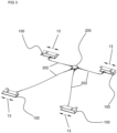
- each of the four motion imparting legs 100 will move back and forth, as shown in the arrows 13 in Figure 3 , with respect to the floor bearing base in an oscillating or reciprocating rectilinear manner. Since the motion imparting legs 100 are connected to the bed frame 12 through the movable upper surface, the rocking bed 10 will oscillate or reciprocate back and forth in a horizontal plane, that is to say it will move rectilinearly, this can be seen by the arrow 14.
- a central hub 200 for controlling and providing power to the motion imparting legs 100 is provided, this can be more easily seen in Figures 2 and 3 .
- the central hub 200 is connected to each motion imparting leg 100 by cabling 202.
- the cabling 202 provides a route for data communication and power.
- the central hub 200 receives data and/or signals from each motion imparting leg 100.
- the central hub may send commands, signals, data and/or information to the or each motion imparting leg 100.
- the central hub 200 may be configured to synchronise the motion of the legs 100.
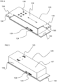
- a motion imparting leg 100 is shown in more detail.
- a base 102 for bearing against the floor is provided.
- the base 102 is preferably rectangular.
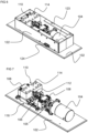
- An electric motor 104 preferably a brushless servo motor, is mounted to the base 102 by means of a bracket or similar.
- a motor shaft extends from a body of the motor partially along the longitudinal length of the base 102. The motor shaft is not visible in the Figures.
- a rotary encoder is attached to the motor shaft within the body of the motor.
- the rotary encoder may be disposed in other positions.
- a motor controller (not shown) is connected to the rotary encoder.
- the motor controller controls the speed of the motor based on the positional data from the rotary encoder.
- the motor controller also controls the speed of the motor based on the desired motion or position path received from the control hub 200.
- the motor controller includes a persistent memory for storing data, especially positional data, while the motion imparting leg 100 is powered down.
- an emergency power store may be provided so that the motor controller can store the required data in the persistent memory in the event of an unexpected loss of power.
- the power store may be a small battery or a capacitor which provides sufficient power to store the positional data in a short time frame, for example 1 second.
- a flexible shaft coupling 105 is provided for coupling rotation of the motor shaft to a leadscrew rod.
- Flexible shaft coupling 105 includes a first end couple with a threaded fastener, a second end couple with a threaded fastener and a flexible central position which allows the first and second end couples to misaligned.
- a leadscrew rod 106 with a threaded portion extending at least partially along the longitudinal length of its body is provided. At one end of the leadscrew rod 106 is provided a non-threaded portion and a coupling portion.
- the coupling portion 107 includes a key with a substantially flat surface for engaging with a threaded fastener. At the other end of the rod is provided a non-threaded portion of the body.
- the coupling portion of the leadscrew rod 106 is inserted into the first end couple of the flexible shaft coupling 105.
- the threaded fastener in the first end couple is tightened and engages with the substantially flat surface of the key.
- the end of the motor shaft is inserted into the second end couple and the threaded fastener is tightened to secure the motor shaft, preferably to a key on the motor shaft.
- the end of the motor shaft and end of the leadscrew rod are substantially disposed on the same axis, that is to say they are substantially concentric, and spaced apart by the flexible coupling 105.
- Leadscrew rod mounting brackets 108 are mounted to the base 102. Each leadscrew mounting bracket 108 includes a through aperture with a bearing disposed therein. The leadscrew rod 106 is located so that the non-threaded portions are disposed to the bearings of the leadscrew rod mounting brackets 108.
- a movable carriage 110 is coupled to the leadscrew rod 106.
- the movable carriage includes a screw nut 112 disposed on the leadscrew rod 106 and a movable block 114 removably coupled to the screw nut 112.
- the shaft of the electric motor 104 rotates which causes the leadscrew rod 106 to rotate.
- the leadscrew rod 106 rotates the movable carriage moves rectilinearly along the threaded portion of the leadscrew rod.
- Each linear slider assembly 116 has a first element in the form of a shaped guide 118 which is mounted to the base 102 and a second element in the form of a sliding block 120.
- Each sliding block 120 includes a recess shaped and sized to receive the shaped guide 118.
- An upper surface of the sliding block 120 includes coupling means for coupling the sliding block to the movable block 114 of the movable carriage 110.
- a linear encoder is disposed to at least one linear slider assembly 116.
- the linear encoder is connected to the motor controller and is used to determine the linear position of sliding block 120 which is used to infer the position of the movable upper surface coupled to the bed frame.
- a wall 122 extends from the surface of the base 102.
- the wall 122 encircles the motor, leadscrew rod, linear slider assemblies, and various other components.
- Flanges 123 extend inwards from one edge of the wall 122. Cut-outs are provided in the flanges to allow the movable block 114 to rectilinearly move.
- a connector port 124 is provided on an outer surface of the wall 122.
- the connector port 124 is electrically connected to the motor controller and provides a data connection between the central hub 200 and the motion imparting leg 100.
- the connector port 124 is also used to connect to a power source. In other embodiments a separate power connector port may be provided. In embodiments comprising a wireless communication means, the connector port may be used as a power connector port.
- a movable shroud 126 is provided.
- the movable shroud 126 includes an upper surface 127 which is substantially planer and a wall 128 depending from the peripheral edge of the upper surface 127.
- a cut-out 129 is provided in the wall 128 so that the movable shroud 126 does not contact the cabling connected to the connector port 124 during the full extent, or length, of rectilinear movement.
- the movable shroud 126 does not extend past the base 102 and remains within the footprint of the base 102 during rectilinear movement.
- the movable shroud 126 is connected to the movable block 114 through fasteners 125, such as threaded bolts, which extend through apertures in the upper surface 127.
- a bearing or similar, may be provided between the movable shroud 126 and the flanges of the wall 122.
- a bed frame mounting bracket 130 is provided.
- the bed frame mounting bracket 130 is plate-like being substantially planer having an upper surface and a lower surface.
- the bed frame mounting bracket 130 may not be plate-like and be constructed to fit different types of bed frames.
- the bed frame mounting bracket 130 is substantially L-shaped.
- the mounting bracket 130 has a main body portion 132 and first and second portions 134 which extend from the main body portion. In other embodiments, the mounting bracket may have a different shape.
- the upper surface of the mounting bracket 130 is in contact with a surface of the bed frame when the motion imparting leg 100 is fitted to the bed frame.
- Coupling apertures 136 sized and shaped to received screws, or other types of fasteners, are provided in both the first and second portions 134.
- the coupling apertures allow the motion imparting leg 100 to be securely fastened to the bed frame by means of fasteners.
- a plurality of mounting apertures 138 are provided in the upper surface of the mounting bracket 130.
- the mounting apertures are sized and shaped to receive a fixing, such as a bolt or other fastener.
- the mounting apertures allow the bed frame mounting bracket 130 to be coupled to the movable shroud 126 and the movable block 114.
- the lower surface of the bed frame mounting bracket 130 is in contact with the upper surface 127 of the movable shroud 126.
- a safety system is provided with the motor controller.
- the safety system may be configured to determine unexpected operation of the motion imparting leg. For example, the safety system may be used to determine if there is a decoupling, either complete or partial, between the rectilinear motion of components, such as the mounting bracket 130, and the rotary motion of the motor shaft.
- the motor controller If a decoupling has been determined, the motor controller generates a warning signal which is transmitted to the central hub 200 via the cabling 202. The central control hub 200 may then generate a shutdown signal which is transmitted to all of the motion imparting legs 100.
- the safety system uses data from the rotary encoder and linear encoder to determine if there is a decoupling. In other embodiments, the safety system uses data from one of the encoders plus a monitored electrical value of the motor, such as current.
- the safety system may be configured to determine excessive rectilinear motion. That is to say, the safety system may determine that the upper surface, preferably the bracket 132, has moved further than one end of its defined motion path length. The safety system may use the rectilinear motion of other components, such as the sliding block 120, carriage 110 or shroud 126, to infer the motion of the upper surface.
- the safety system includes two optical switches 140 connected to the motor controller. Each optical switch 140 is disposed towards an end of the linear slider assembly 116, specifically the shaped guide 118. Each optical switch 140 has a switch gate comprised of two pillars with a light path disposed therebetween.
- a blade 142 or similar switch trigger means, is disposed on either end of the sliding block 120. Each blade extends out from the block towards an optical switch 140. The blade 142 actuates the optical switch by interrupting the light path in the switch gate.
- the motor controller If the optical switches 140 are actuated, the motor controller generates a warning signal which is transmitted to the central hub 200 via the cabling 202.
- the central control hub 200 may then generate a shutdown signal which is transmitted to all of the motion imparting legs 100.
- optical switches may also be used in a method of calibrating a motion imparting leg. The method will now be described with reference to the embodiments discussed above, however it is applicable to other types of motion imparting legs.
- the motor 104 drives the carriage assembly 110 and sliding blocks 120 until a blade 142 actuates an optical switch 140.
- the actuation of the optical switch 140 is indicative of the end of the rectilinear motion path.
- the motor controller records positional data indicative of the end of the motion path.
- the motion imparting leg 100 undergoes the same steps but reverses the direction of the motor 104 to determine the other end of the rectilinear path.
- the optical switches 140 are not to be triggered during normal operation of the motion imparting leg 100. This means that the actual motion path length has to be less than the maximum motion path length so that the blades 142 do not trigger the optical switches 142. In the current embodiment, the actual motion path length will be 4mm smaller than the maximum motion path length, that is to say there is a margin of 2mm at either end.
Landscapes
- Engineering & Computer Science (AREA)
- Health & Medical Sciences (AREA)
- General Health & Medical Sciences (AREA)
- Nursing (AREA)
- Physics & Mathematics (AREA)
- Chemical & Material Sciences (AREA)
- Combustion & Propulsion (AREA)
- Electromagnetism (AREA)
- Power Engineering (AREA)
- Invalid Beds And Related Equipment (AREA)
Claims (15)
- Bewegungsübertragendes Bein (100) zum Übertragen einer oszillierenden oder hin- und hergehenden geradlinigen Bewegung (13) auf ein Schaukelbett (10), umfassend:eine Basis (102); undeine obere Oberfläche (127), die relativ zur Basis (102) beweglich ist, um die oszillierende oder hin- und hergehende Bewegung zu bewirken;dadurch gekennzeichnet, dass das bewegungsübertragende Bein (100) ferner einen Servomotor (104), der so konfiguriert ist, dass er mit niedriger Geschwindigkeit und hohem Drehmoment arbeitet, um die Bewegung der oberen Oberfläche (127) anzutreiben, ein Positionserfassungsmittel zum Bestimmen der Rotationsposition des Servomotors (104) oder der Position der oberen Oberfläche (127) und eine Motorsteuerung umfasst, die so konfiguriert ist, dass sie eine feldorientierte Steuerung verwendet, um den Servomotor (104) basierend auf Daten von dem Positionserfassungsmittel zu steuern.
- Bewegungsübertragendes Bein (100) nach Anspruch 1, bei dem das Positionserfassungsmittel einen Rotationscodierer, der an dem Rotor oder der Welle des Servomotors angeordnet ist, und/oder einen linearen Codierer zum Codieren der Position der oberen Oberfläche (127) einschließt.
- Bewegungsübertragendes Bein (100) nach Anspruch 1 oder 2, das ferner eine geradlinige Bewegungsbaugruppe zur Umwandlung der Rotation der Welle des Servomotors (104) in eine geradlinige Bewegung der oberen Oberfläche (127) umfasst, die geradlinige Bewegungsbaugruppe eine Gewindestange (106) umfasst, die drehbar mit der Welle des Servomotors (104) gekoppelt und mit der oberen Oberfläche (127) verbunden ist, wobei die Gewindestange (106) und die Welle im Wesentlichen auf derselben Achse ausgerichtet sind, wobei vorzugsweise eine flexible Kupplung (105) bereitgestellt wird, um ein Ende der Gewindestange (106) mit einem Ende der Welle des Servomotors (104) zu koppeln.
- Bewegungsübertragendes Bein (100) nach Anspruch 3, wobei die geradlinige Bewegungsbaugruppe einen beweglichen Schlitten (110) umfasst, der an der Gewindestange (106) angeordnet und mit der oberen Oberfläche (127) gekoppelt ist, wobei die Rotation der Servomotorwelle die Gewindestange (106) dreht, wodurch der bewegliche Schlitten (110) sich geradlinig entlang der Stange (106) bewegt.
- Bewegungsübertragendes Bein nach Anspruch 4, bei dem der bewegliche Schlitten (110) eine lineare Gleiterbaugruppe (116) parallel zu der Gewindestange (106) umfasst, wobei die lineare Gleiterbaugruppe vorzugsweise ein erstes, mit dem beweglichen Schlitten gekoppeltes Gleitelement und ein zweites, an der Basis angeordnetes Gleitelement umfasst.
- Bewegungsübertragendes Bein (100) nach Anspruch 5, in Abhängigkeit von Anspruch 2, bei dem der lineare Codierer an der linearen Gleiterbaugruppe (116) angeordnet ist.
- Bewegungsübertragbares Bein (100) nach einem der vorstehenden Ansprüche, bei dem die Steuerung ein Kommunikationsmittel zum Empfangen und/oder Senden von Daten an einen zentralen Steuerungsknoten (200) oder ein ähnliches bewegungsübertragbares Bein umfasst, wobei das Kommunikationsmittel vorzugsweise mindestens eines von einem drahtgebundenen Kommunikationsmittel und einem drahtlosen Kommunikationsmittel einschließt.
- Bewegungsübertragendes Bein (100) nach einem der vorstehenden Ansprüche, das ferner ein Sicherheitssystem zum Überwachen des erwartungsgemäßen Betriebs des bewegungsübertragenden Beins (100) umfasst, wobei das Sicherheitssystem ein Warnsignal erzeugt, wenn das bewegungsübertragende Bein (100) unerwartet in Betrieb ist.
- Bewegungsübertragendes Bein (100) nach Anspruch 8, bei dem das Sicherheitssystem so konfiguriert ist, dass es mindestens eine Entkopplung zwischen der Rotationsbewegung der Servomotorwelle und der geradlinigen Bewegung der oberen Oberfläche (127) und eine übermäßige geradlinige Bewegung über zwei vorbestimmte Punkte auf einem geradlinigen Weg hinaus überwacht, wobei das Sicherheitssystem vorzugsweise zwei optische Schalter (140) zur Bestimmung einer übermäßigen geradlinigen Bewegung einschließt.
- Bewegungsübertragendes Bein (100) nach einem der vorstehenden Ansprüche, ferner umfassend ein Notenergieversorgungssystem, das so konfiguriert ist, dass es die Motorsteuerung mit Energie versorgt, um im Falle eines Stromausfalls Positionsdaten zu speichern.
- Bewegungsübertragendes Bein (100) nach einem der vorstehenden Ansprüche, bei dem die Motorsteuerung so konfiguriert ist, dass sie Positionsdaten in einem permanenten Speicher speichert, wenn der Motor zu rotieren stoppt.
- Bewegungsübertragendes Bein (100) nach einem der vorstehenden Ansprüche, wobei das bewegungsübertragende Bein ohne Schneckenrad- oder Riemenscheibenuntersetzer bereitgestellt ist.
- Kit mit Teilen, die eine Vielzahl von bewegungsübertragenden Beinen (100) nach einem der vorstehenden Ansprüche umfassen, wobei der Kit mit Teilen vorzugsweise ferner eine zentrale Steuerung (200) zur Verbindung mit jedem bewegungsübertragenden Bein (100) umfasst, wobei der zentrale Steuerungsknoten (200) die geradlinige Bewegung der bewegungsübertragenden Beine (100) synchronisiert.
- Schaukelbett (10), das mit einer Vielzahl von bewegungsübertragenden Beinen (100) nach einem der Ansprüche 1 bis 12 nachgerüstet ist, wobei die bewegliche Oberfläche (127) jedes bewegungsübertragenden Beines (100) abnehmbar an einen Bettrahmen oder ein Bein des Bettes gekoppelt ist.
- Schaukelbett (10), umfassend einen Bettrahmen und eine Vielzahl von bewegungsübertragenden Beinen nach einem der Ansprüche 1 bis 12, wobei die bewegungsübertragenden Beine (100) um den Umfang des Bettrahmens herum angebracht sind.
Applications Claiming Priority (1)
| Application Number | Priority Date | Filing Date | Title |
|---|---|---|---|
| GB2111833.6A GB2610164A (en) | 2021-08-18 | 2021-08-18 | Improved rocking legs for a bed |
Publications (3)
| Publication Number | Publication Date |
|---|---|
| EP4137008A1 EP4137008A1 (de) | 2023-02-22 |
| EP4137008B1 true EP4137008B1 (de) | 2024-04-03 |
| EP4137008C0 EP4137008C0 (de) | 2024-04-03 |
Family
ID=77859882
Family Applications (1)
| Application Number | Title | Priority Date | Filing Date |
|---|---|---|---|
| EP22187943.0A Active EP4137008B1 (de) | 2021-08-18 | 2022-07-29 | Verbesserte schaukelbeine für ein bett |
Country Status (4)
| Country | Link |
|---|---|
| US (1) | US12290178B2 (de) |
| EP (1) | EP4137008B1 (de) |
| CN (1) | CN114794786B (de) |
| GB (1) | GB2610164A (de) |
Families Citing this family (3)
| Publication number | Priority date | Publication date | Assignee | Title |
|---|---|---|---|---|
| ES1305082Y (es) * | 2023-10-19 | 2024-04-09 | Munoz Jaime De Los Reyes Morales | Dispositivo de balanceo de un soporte para bebes |
| GB2637011A (en) | 2024-01-03 | 2025-07-09 | Inoveris Solutions Srl | System and methods for improving sleep quality |
| GB2641003A (en) * | 2024-01-04 | 2025-11-19 | Inoveris Solutions Srl | A motion imparting leg for rocking a bed |
Family Cites Families (49)
| Publication number | Priority date | Publication date | Assignee | Title |
|---|---|---|---|---|
| FR1103398A (fr) | 1954-07-02 | 1955-11-02 | Mécanisme pour communiquer un mouvement de va-et-vient à des berceaux et voitures similaires | |
| US2888086A (en) * | 1957-09-06 | 1959-05-26 | Daniel C O'brien | Carriage oscillating device |
| US3934283A (en) * | 1974-06-17 | 1976-01-27 | Raffel Marvin J | Bed frame with readily connectable vibrator motors |
| DE3307623C2 (de) * | 1983-03-04 | 1986-06-05 | Lenze GmbH & Co KG Aerzen, 3258 Aerzen | Verfahren und Schaltungsanordnung zur Regelung eines Wechselstrom- oder Drehstrommotors |
| US4713745A (en) * | 1986-07-22 | 1987-12-15 | Westinghouse Electric Corp. | Vector-controlled unrestricted frequency changer (UFC) system and variable speed AC motor drive using such a system |
| US4793010A (en) * | 1987-10-28 | 1988-12-27 | General Ideas & Products Ltd. | Baby rocker apparatus |
| FR2649872B1 (fr) | 1989-05-11 | 1992-02-21 | Canovas Gines | Dispositif pour bercer les jeunes enfants |
| US5037375A (en) | 1989-09-29 | 1991-08-06 | Infant Advantage, Inc. | Individual environmental control method |
| CN2087461U (zh) | 1990-06-15 | 1991-10-30 | 秦皓 | 婴儿床、童车自动摇晃底盘 |
| US6217214B1 (en) * | 1993-11-22 | 2001-04-17 | Hologic, Inc. | X-ray bone densitometry apparatus |
| US5668421A (en) * | 1995-04-06 | 1997-09-16 | E. B. Eddy Forest Products Ltd. | Pressurized air-gap guided active linear motor suspension system |
| US5923144A (en) * | 1996-06-28 | 1999-07-13 | Allen-Bradley Company, Llc | Frequency generator for a motor controller |
| BR9712418A (pt) * | 1996-10-22 | 2000-07-11 | Infant Advantage Inc | Mecanismo de acionamento para uma estrutura de colchão, plataforma de movimento dispositivo de controle para um mecanismo de acionamento |
| DE29710002U1 (de) | 1997-06-09 | 1997-09-04 | Olsen Joerg Dipl Betriebsw | Kinderwagen |
| US5880416A (en) * | 1997-12-22 | 1999-03-09 | Otis Elevator Company | Automatic calibration of motor speed loop gain for an elevator motor control |
| KR200235182Y1 (ko) | 1997-12-31 | 2001-10-25 | 김도형 | 유아용 자동침대의 구동장치 |
| US6139324A (en) * | 1998-03-04 | 2000-10-31 | D-Box Audio Inc. | Multi-sense home entertainment chair transducer system |
| DE19841592A1 (de) | 1998-09-11 | 2000-03-23 | Knappe Dietmar | Vorrichtung zum Hin- und Herschieben eines Kinderwagens |
| TW463751U (en) | 2000-06-09 | 2001-11-11 | Chen Jeng Yi | The recycle system with electronic of baby car |
| CN2500180Y (zh) | 2001-09-14 | 2002-07-17 | 魏和斌 | 一种电动摇椅 |
| ATE453346T1 (de) * | 2004-03-08 | 2010-01-15 | Mitchell Christopher Robert Mu | Schaukelvorrichtung für eine umhegung für kleinkinder |
| US7281284B2 (en) * | 2005-10-31 | 2007-10-16 | Sims Jr Dewey M | Variable motion rocking bed |
| US8187111B2 (en) * | 2005-11-03 | 2012-05-29 | Graco Children's Products Inc. | Child motion device |
| ITTO20060133U1 (it) | 2006-09-12 | 2008-03-13 | Makeridea S R L | Apparato per la vibrazione di un lettino, una culla o simili. |
| US8239984B2 (en) * | 2008-09-03 | 2012-08-14 | Thorley Industries Llc | Variable motion infant seat utilizing constant motor speed |
| TWM360624U (en) | 2009-03-03 | 2009-07-11 | Ying-Su Zhong | Electric rocking bed and chair structures |
| CN201598279U (zh) * | 2009-12-01 | 2010-10-06 | 杭州博日科技有限公司 | 偏心旋转/往复运动自动切换的振荡培养箱 |
| US8856982B1 (en) * | 2010-07-13 | 2014-10-14 | Christopher George Kalivas | Motion bed |
| ES2383364B1 (es) | 2010-10-27 | 2013-05-06 | Universidad De Valladolid | Dispositivo de acunado automático |
| JP5440538B2 (ja) * | 2011-03-31 | 2014-03-12 | ブラザー工業株式会社 | モータ制御装置及び画像形成装置 |
| US9332859B2 (en) | 2014-03-04 | 2016-05-10 | LeRahn Murray | Bassinet apparatus |
| EP3001548B1 (de) * | 2014-09-29 | 2019-07-03 | Airbus Operations GmbH | Notstromversorgungssystem, Flugzeug mit einem solchen Notstromversorgungssystem und Verfahren zur Bereitstellung zumindest von elektrischer Energie und hydraulischer Energie in einem Notfall in einem Flugzeug |
| CN204378607U (zh) | 2015-01-30 | 2015-06-10 | 三峡大学 | 基于智能手机监控的电动婴儿摇床 |
| US10258761B2 (en) | 2015-04-16 | 2019-04-16 | Graco Children's Products Inc. | Children's product with synchronized sound and non-sound output |
| JP6602044B2 (ja) * | 2015-05-08 | 2019-11-06 | キヤノン株式会社 | 振動型駆動装置、制御装置及び医用システム |
| CN109496394B (zh) * | 2016-07-14 | 2022-06-14 | 株式会社富士 | 位置管理装置及护理装置 |
| CN206213669U (zh) * | 2016-08-18 | 2017-06-06 | 张永华 | 一种电动摇摆婴儿床 |
| EP3318162A1 (de) | 2016-11-03 | 2018-05-09 | Adiva Sprl | Modulares schaukelbett mit programmierbarer steuerung |
| CN206852384U (zh) * | 2017-01-03 | 2018-01-09 | 胡屹博 | 成人摇篮 |
| WO2018170072A1 (en) * | 2017-03-15 | 2018-09-20 | Halo Maritime Defense Systems, Inc. | Automatic gate operation and system status indication for marine barriers and gate systems |
| EP3375374B1 (de) * | 2017-03-17 | 2023-07-05 | Agfa Nv | Schiebeanordnung für mobiles tomosynthese-röntgensystem |
| CN107061182B (zh) * | 2017-03-27 | 2019-01-29 | 武汉科技大学 | 一种往复振荡式扑翼能量转换装置 |
| CN108288936B (zh) * | 2018-01-03 | 2020-12-25 | 东南大学 | 一种永磁直线电机低速无位置传感器控制方法 |
| JP7637051B2 (ja) * | 2018-11-09 | 2025-02-27 | オリ インコーポレイテッド | 可動ロボット要素の改良された動作のためのシステムおよび方法 |
| US11944212B2 (en) * | 2019-09-19 | 2024-04-02 | Thorley Industries, Llc | Infant care apparatus |
| US11134786B2 (en) * | 2019-10-31 | 2021-10-05 | Vikram Sharma | Furniture with a built-in joyride |
| EP4082396A1 (de) * | 2019-12-23 | 2022-11-02 | Kamei, Masamichi | Oszillierendes schlafinduktionsbett |
| CN213820648U (zh) * | 2020-12-28 | 2021-07-30 | 慕思健康睡眠股份有限公司 | 一种摇摆床 |
| US20210354566A1 (en) * | 2021-06-21 | 2021-11-18 | Jacob Ben-Ari | Scalable Tractive-Power System For Electric Railway-Vehicles Integrated into All-Wheel Electric Steering and Electric Braking Systems, Deriving 90% To 99% Traction and Dynamic Efficiency |
-
2021
- 2021-08-18 GB GB2111833.6A patent/GB2610164A/en active Pending
-
2022
- 2022-06-20 CN CN202210699932.4A patent/CN114794786B/zh active Active
- 2022-06-28 US US17/851,974 patent/US12290178B2/en active Active
- 2022-07-29 EP EP22187943.0A patent/EP4137008B1/de active Active
Also Published As
| Publication number | Publication date |
|---|---|
| US12290178B2 (en) | 2025-05-06 |
| CN114794786B (zh) | 2024-05-28 |
| EP4137008A1 (de) | 2023-02-22 |
| EP4137008C0 (de) | 2024-04-03 |
| GB202111833D0 (en) | 2021-09-29 |
| CN114794786A (zh) | 2022-07-29 |
| US20230053418A1 (en) | 2023-02-23 |
| GB2610164A (en) | 2023-03-01 |
Similar Documents
| Publication | Publication Date | Title |
|---|---|---|
| EP4137008B1 (de) | Verbesserte schaukelbeine für ein bett | |
| DK2415161T3 (en) | Linear drive and table with linear drive and motor to the linear drive | |
| US7654382B2 (en) | Table drive system | |
| EP3378154B1 (de) | Ein linearantrieb mit einem bürstenlosen dc motor | |
| JPH0582998A (ja) | 部品取付装置 | |
| JP2004116283A (ja) | ドアの非接触式直線移動を引き起こす装置およびドアの制御方法 | |
| US12535123B2 (en) | Electric motor having stationary drive mechanism | |
| KR20170001159A (ko) | 직선 구동식 액츄에이터 및 그 제어방법 | |
| CN111799938A (zh) | 电动推杆系统、沙发床及其控制方法 | |
| KR20180118946A (ko) | Bldc모터의 회전각 초기위치 검출장치 및 그 방법 | |
| CN120433637A (zh) | 一种无刷行星机器人关节电机及其多位置反馈与控制方法 | |
| US20250221543A1 (en) | Motion imparting leg for rocking a bed | |
| CN117879221A (zh) | 一种利于拆装的电机及其拆装方法 | |
| CN113783497A (zh) | 滤波器调频控制方法 | |
| US20200343786A1 (en) | Packaging structure for a motor casing | |
| CN118232605B (zh) | 一种往复伸缩与振动的电机驱动机构 | |
| TWI692178B (zh) | 高效率之智慧型馬達 | |
| US20250330060A1 (en) | Motor driven mechanism capable of reciprocating extension/retraction and vibration | |
| CN218979607U (zh) | 膝关节训练设备 | |
| US12348172B2 (en) | Control unit for controlling a motor | |
| CN211426782U (zh) | 一种雷达引导头自动安装调试设备 | |
| JP2019147344A (ja) | 電動射出成形機 | |
| JP4536203B2 (ja) | エンコーダ組付機能付ミシン | |
| CN209363855U (zh) | 一种全自动高精度激光切割设备 | |
| Solovyev | Microprocessor Control of the Sonar Electric Drive |
Legal Events
| Date | Code | Title | Description |
|---|---|---|---|
| PUAI | Public reference made under article 153(3) epc to a published international application that has entered the european phase |
Free format text: ORIGINAL CODE: 0009012 |
|
| STAA | Information on the status of an ep patent application or granted ep patent |
Free format text: STATUS: THE APPLICATION HAS BEEN PUBLISHED |
|
| AK | Designated contracting states |
Kind code of ref document: A1 Designated state(s): AL AT BE BG CH CY CZ DE DK EE ES FI FR GB GR HR HU IE IS IT LI LT LU LV MC MK MT NL NO PL PT RO RS SE SI SK SM TR |
|
| STAA | Information on the status of an ep patent application or granted ep patent |
Free format text: STATUS: REQUEST FOR EXAMINATION WAS MADE |
|
| 17P | Request for examination filed |
Effective date: 20230719 |
|
| RBV | Designated contracting states (corrected) |
Designated state(s): AL AT BE BG CH CY CZ DE DK EE ES FI FR GB GR HR HU IE IS IT LI LT LU LV MC MK MT NL NO PL PT RO RS SE SI SK SM TR |
|
| GRAP | Despatch of communication of intention to grant a patent |
Free format text: ORIGINAL CODE: EPIDOSNIGR1 |
|
| STAA | Information on the status of an ep patent application or granted ep patent |
Free format text: STATUS: GRANT OF PATENT IS INTENDED |
|
| RIC1 | Information provided on ipc code assigned before grant |
Ipc: A47D 9/04 20060101ALI20231106BHEP Ipc: A47C 21/00 20060101AFI20231106BHEP |
|
| INTG | Intention to grant announced |
Effective date: 20231204 |
|
| GRAS | Grant fee paid |
Free format text: ORIGINAL CODE: EPIDOSNIGR3 |
|
| GRAA | (expected) grant |
Free format text: ORIGINAL CODE: 0009210 |
|
| STAA | Information on the status of an ep patent application or granted ep patent |
Free format text: STATUS: THE PATENT HAS BEEN GRANTED |
|
| AK | Designated contracting states |
Kind code of ref document: B1 Designated state(s): AL AT BE BG CH CY CZ DE DK EE ES FI FR GB GR HR HU IE IS IT LI LT LU LV MC MK MT NL NO PL PT RO RS SE SI SK SM TR |
|
| REG | Reference to a national code |
Ref country code: CH Ref legal event code: EP |
|
| REG | Reference to a national code |
Ref country code: IE Ref legal event code: FG4D |
|
| REG | Reference to a national code |
Ref country code: DE Ref legal event code: R096 Ref document number: 602022002674 Country of ref document: DE |
|
| U01 | Request for unitary effect filed |
Effective date: 20240411 |
|
| U07 | Unitary effect registered |
Designated state(s): AT BE BG DE DK EE FI FR IT LT LU LV MT NL PT SE SI Effective date: 20240419 |
|
| U20 | Renewal fee for the european patent with unitary effect paid |
Year of fee payment: 3 Effective date: 20240623 |
|
| PG25 | Lapsed in a contracting state [announced via postgrant information from national office to epo] |
Ref country code: IS Free format text: LAPSE BECAUSE OF FAILURE TO SUBMIT A TRANSLATION OF THE DESCRIPTION OR TO PAY THE FEE WITHIN THE PRESCRIBED TIME-LIMIT Effective date: 20240803 |
|
| PG25 | Lapsed in a contracting state [announced via postgrant information from national office to epo] |
Ref country code: HR Free format text: LAPSE BECAUSE OF FAILURE TO SUBMIT A TRANSLATION OF THE DESCRIPTION OR TO PAY THE FEE WITHIN THE PRESCRIBED TIME-LIMIT Effective date: 20240403 |
|
| PG25 | Lapsed in a contracting state [announced via postgrant information from national office to epo] |
Ref country code: GR Free format text: LAPSE BECAUSE OF FAILURE TO SUBMIT A TRANSLATION OF THE DESCRIPTION OR TO PAY THE FEE WITHIN THE PRESCRIBED TIME-LIMIT Effective date: 20240704 |
|
| PG25 | Lapsed in a contracting state [announced via postgrant information from national office to epo] |
Ref country code: ES Free format text: LAPSE BECAUSE OF FAILURE TO SUBMIT A TRANSLATION OF THE DESCRIPTION OR TO PAY THE FEE WITHIN THE PRESCRIBED TIME-LIMIT Effective date: 20240403 |
|
| PG25 | Lapsed in a contracting state [announced via postgrant information from national office to epo] |
Ref country code: CZ Free format text: LAPSE BECAUSE OF FAILURE TO SUBMIT A TRANSLATION OF THE DESCRIPTION OR TO PAY THE FEE WITHIN THE PRESCRIBED TIME-LIMIT Effective date: 20240403 |
|
| PG25 | Lapsed in a contracting state [announced via postgrant information from national office to epo] |
Ref country code: PL Free format text: LAPSE BECAUSE OF FAILURE TO SUBMIT A TRANSLATION OF THE DESCRIPTION OR TO PAY THE FEE WITHIN THE PRESCRIBED TIME-LIMIT Effective date: 20240403 |
|
| PG25 | Lapsed in a contracting state [announced via postgrant information from national office to epo] |
Ref country code: PL Free format text: LAPSE BECAUSE OF FAILURE TO SUBMIT A TRANSLATION OF THE DESCRIPTION OR TO PAY THE FEE WITHIN THE PRESCRIBED TIME-LIMIT Effective date: 20240403 Ref country code: IS Free format text: LAPSE BECAUSE OF FAILURE TO SUBMIT A TRANSLATION OF THE DESCRIPTION OR TO PAY THE FEE WITHIN THE PRESCRIBED TIME-LIMIT Effective date: 20240803 Ref country code: HR Free format text: LAPSE BECAUSE OF FAILURE TO SUBMIT A TRANSLATION OF THE DESCRIPTION OR TO PAY THE FEE WITHIN THE PRESCRIBED TIME-LIMIT Effective date: 20240403 Ref country code: GR Free format text: LAPSE BECAUSE OF FAILURE TO SUBMIT A TRANSLATION OF THE DESCRIPTION OR TO PAY THE FEE WITHIN THE PRESCRIBED TIME-LIMIT Effective date: 20240704 Ref country code: ES Free format text: LAPSE BECAUSE OF FAILURE TO SUBMIT A TRANSLATION OF THE DESCRIPTION OR TO PAY THE FEE WITHIN THE PRESCRIBED TIME-LIMIT Effective date: 20240403 Ref country code: CZ Free format text: LAPSE BECAUSE OF FAILURE TO SUBMIT A TRANSLATION OF THE DESCRIPTION OR TO PAY THE FEE WITHIN THE PRESCRIBED TIME-LIMIT Effective date: 20240403 Ref country code: RS Free format text: LAPSE BECAUSE OF FAILURE TO SUBMIT A TRANSLATION OF THE DESCRIPTION OR TO PAY THE FEE WITHIN THE PRESCRIBED TIME-LIMIT Effective date: 20240703 |
|
| REG | Reference to a national code |
Ref country code: DE Ref legal event code: R097 Ref document number: 602022002674 Country of ref document: DE |
|
| PG25 | Lapsed in a contracting state [announced via postgrant information from national office to epo] |
Ref country code: SK Free format text: LAPSE BECAUSE OF FAILURE TO SUBMIT A TRANSLATION OF THE DESCRIPTION OR TO PAY THE FEE WITHIN THE PRESCRIBED TIME-LIMIT Effective date: 20240403 Ref country code: RO Free format text: LAPSE BECAUSE OF FAILURE TO SUBMIT A TRANSLATION OF THE DESCRIPTION OR TO PAY THE FEE WITHIN THE PRESCRIBED TIME-LIMIT Effective date: 20240403 |
|
| PG25 | Lapsed in a contracting state [announced via postgrant information from national office to epo] |
Ref country code: SM Free format text: LAPSE BECAUSE OF FAILURE TO SUBMIT A TRANSLATION OF THE DESCRIPTION OR TO PAY THE FEE WITHIN THE PRESCRIBED TIME-LIMIT Effective date: 20240403 |
|
| PG25 | Lapsed in a contracting state [announced via postgrant information from national office to epo] |
Ref country code: SM Free format text: LAPSE BECAUSE OF FAILURE TO SUBMIT A TRANSLATION OF THE DESCRIPTION OR TO PAY THE FEE WITHIN THE PRESCRIBED TIME-LIMIT Effective date: 20240403 Ref country code: SK Free format text: LAPSE BECAUSE OF FAILURE TO SUBMIT A TRANSLATION OF THE DESCRIPTION OR TO PAY THE FEE WITHIN THE PRESCRIBED TIME-LIMIT Effective date: 20240403 Ref country code: RO Free format text: LAPSE BECAUSE OF FAILURE TO SUBMIT A TRANSLATION OF THE DESCRIPTION OR TO PAY THE FEE WITHIN THE PRESCRIBED TIME-LIMIT Effective date: 20240403 |
|
| PG25 | Lapsed in a contracting state [announced via postgrant information from national office to epo] |
Ref country code: MC Free format text: LAPSE BECAUSE OF FAILURE TO SUBMIT A TRANSLATION OF THE DESCRIPTION OR TO PAY THE FEE WITHIN THE PRESCRIBED TIME-LIMIT Effective date: 20240403 |
|
| PLBE | No opposition filed within time limit |
Free format text: ORIGINAL CODE: 0009261 |
|
| STAA | Information on the status of an ep patent application or granted ep patent |
Free format text: STATUS: NO OPPOSITION FILED WITHIN TIME LIMIT |
|
| 26N | No opposition filed |
Effective date: 20250106 |
|
| PGFP | Annual fee paid to national office [announced via postgrant information from national office to epo] |
Ref country code: NO Payment date: 20250618 Year of fee payment: 4 |
|
| U20 | Renewal fee for the european patent with unitary effect paid |
Year of fee payment: 4 Effective date: 20250617 |
|
| PG25 | Lapsed in a contracting state [announced via postgrant information from national office to epo] |
Ref country code: IE Free format text: LAPSE BECAUSE OF NON-PAYMENT OF DUE FEES Effective date: 20240729 |
|
| PGFP | Annual fee paid to national office [announced via postgrant information from national office to epo] |
Ref country code: CH Payment date: 20250801 Year of fee payment: 4 |
|
| PG25 | Lapsed in a contracting state [announced via postgrant information from national office to epo] |
Ref country code: CY Free format text: LAPSE BECAUSE OF FAILURE TO SUBMIT A TRANSLATION OF THE DESCRIPTION OR TO PAY THE FEE WITHIN THE PRESCRIBED TIME-LIMIT; INVALID AB INITIO Effective date: 20220729 |
|
| PG25 | Lapsed in a contracting state [announced via postgrant information from national office to epo] |
Ref country code: HU Free format text: LAPSE BECAUSE OF FAILURE TO SUBMIT A TRANSLATION OF THE DESCRIPTION OR TO PAY THE FEE WITHIN THE PRESCRIBED TIME-LIMIT; INVALID AB INITIO Effective date: 20220729 |