EP4136757B1 - Antennenanordnung für ein fahrzeug - Google Patents
Antennenanordnung für ein fahrzeug Download PDFInfo
- Publication number
- EP4136757B1 EP4136757B1 EP21721375.0A EP21721375A EP4136757B1 EP 4136757 B1 EP4136757 B1 EP 4136757B1 EP 21721375 A EP21721375 A EP 21721375A EP 4136757 B1 EP4136757 B1 EP 4136757B1
- Authority
- EP
- European Patent Office
- Prior art keywords
- antenna
- antenna assembly
- vehicle
- modem
- router
- Prior art date
- Legal status (The legal status is an assumption and is not a legal conclusion. Google has not performed a legal analysis and makes no representation as to the accuracy of the status listed.)
- Active
Links
Images


Classifications
-
- H—ELECTRICITY
- H01—ELECTRIC ELEMENTS
- H01Q—ANTENNAS, i.e. RADIO AERIALS
- H01Q1/00—Details of, or arrangements associated with, antennas
- H01Q1/02—Arrangements for de-icing; Arrangements for drying-out ; Arrangements for cooling; Arrangements for preventing corrosion
-
- H—ELECTRICITY
- H01—ELECTRIC ELEMENTS
- H01Q—ANTENNAS, i.e. RADIO AERIALS
- H01Q1/00—Details of, or arrangements associated with, antennas
- H01Q1/27—Adaptation for use in or on movable bodies
- H01Q1/32—Adaptation for use in or on road or rail vehicles
- H01Q1/325—Adaptation for use in or on road or rail vehicles characterised by the location of the antenna on the vehicle
- H01Q1/3275—Adaptation for use in or on road or rail vehicles characterised by the location of the antenna on the vehicle mounted on a horizontal surface of the vehicle, e.g. on roof, hood, trunk
-
- H—ELECTRICITY
- H01—ELECTRIC ELEMENTS
- H01Q—ANTENNAS, i.e. RADIO AERIALS
- H01Q21/00—Antenna arrays or systems
- H01Q21/28—Combinations of substantially independent non-interacting antenna units or systems
-
- H—ELECTRICITY
- H04—ELECTRIC COMMUNICATION TECHNIQUE
- H04B—TRANSMISSION
- H04B1/00—Details of transmission systems, not covered by a single one of groups H04B3/00 - H04B13/00; Details of transmission systems not characterised by the medium used for transmission
- H04B1/02—Transmitters
- H04B1/03—Constructional details, e.g. casings, housings
- H04B1/036—Cooling arrangements
-
- H—ELECTRICITY
- H04—ELECTRIC COMMUNICATION TECHNIQUE
- H04B—TRANSMISSION
- H04B1/00—Details of transmission systems, not covered by a single one of groups H04B3/00 - H04B13/00; Details of transmission systems not characterised by the medium used for transmission
- H04B1/38—Transceivers, i.e. devices in which transmitter and receiver form a structural unit and in which at least one part is used for functions of transmitting and receiving
- H04B1/3822—Transceivers, i.e. devices in which transmitter and receiver form a structural unit and in which at least one part is used for functions of transmitting and receiving specially adapted for use in vehicles
-
- H—ELECTRICITY
- H04—ELECTRIC COMMUNICATION TECHNIQUE
- H04W—WIRELESS COMMUNICATION NETWORKS
- H04W52/00—Power management, e.g. Transmission Power Control [TPC] or power classes
- H04W52/02—Power saving arrangements
- H04W52/0209—Power saving arrangements in terminal devices
- H04W52/0225—Power saving arrangements in terminal devices using monitoring of external events, e.g. the presence of a signal
-
- Y—GENERAL TAGGING OF NEW TECHNOLOGICAL DEVELOPMENTS; GENERAL TAGGING OF CROSS-SECTIONAL TECHNOLOGIES SPANNING OVER SEVERAL SECTIONS OF THE IPC; TECHNICAL SUBJECTS COVERED BY FORMER USPC CROSS-REFERENCE ART COLLECTIONS [XRACs] AND DIGESTS
- Y02—TECHNOLOGIES OR APPLICATIONS FOR MITIGATION OR ADAPTATION AGAINST CLIMATE CHANGE
- Y02D—CLIMATE CHANGE MITIGATION TECHNOLOGIES IN INFORMATION AND COMMUNICATION TECHNOLOGIES [ICT], I.E. INFORMATION AND COMMUNICATION TECHNOLOGIES AIMING AT THE REDUCTION OF THEIR OWN ENERGY USE
- Y02D30/00—Reducing energy consumption in communication networks
- Y02D30/70—Reducing energy consumption in communication networks in wireless communication networks
Definitions
- a modem for the vehicle In wireless communication systems for vehicles, a modem for the vehicle is typically placed a great distance away from an antenna in order to prevent electro-magnetic signals from the modem from interfering with the antenna. This often requires a long coaxial cable wired throughout the vehicle.
- BLUETOOTH technology is a standard short range radio link that operates in the unlicensed 2.4 gigahertz band.
- CDMA Code Division Multiple Access
- GSM Global System for Mobile Communications
- GSM Global System for Mobile Communications
- the Universal Mobile Telecommunications System (“UMTS”) is a wireless standard.
- LTE Long Term Evolution
- LTE Frequency Bands include 698-798MHz (Band 12, 13, 14, 17); 791-960MHz (Band 5, 6, 8, 18,19,20); 1710-2170MHz (Band 1, 2, 3, 4, 9, 10, 23, 25, 33, 34, 35, 36, 37, 39); 1427-1660.5MH (Band 11, 21, 24); 2300-2700MHz (Band 7, 38, 40, 41); 3400-3800MHz (Band 22, 42, 43).
- Antenna impedance and the quality of the impedance match are most commonly characterized by either return loss or Voltage Standing Wave Ratio.
- SMT Surface Mount Technology
- the APPLE IPHONE ® 5 LTE Bands include: LTE700 /1700/2100 (698-806MHz/ 1710- 1785MHz/ 1920-2170MHz); LTE 850/1800/2100 (824- 894MHz/ 1710- 1880MHz/ 1920-2170MHz); and LTE 700/850/1800/1900/2100 (698-806MHz/824-894MHz/1710-1880MHz/1850- 1990MHz/l 920/2170).
- the SAMSUNG GALAXY ® Sill LTE Bands include: LTE 800/1800/2600 (806-869MHz/l 710- 1880MHz/2496-2690MHz.
- the NOKIA LUMIA ® 920 LTE Bands LTE 700/1700/2100 (698-806MHz/ 1710- 1785MHz/ 1920-2170MHz); LTE 800/900/1800/2100/2600 (806-869MHz/880-960MHz/l 710- 1880MHz/l 920-2170MHz/2496-2690MHz).
- the long coaxial cable that connects a modem to an antenna on a vehicle leads to signal losses due to the length of the coaxial cable.
- a satellite antenna terminal includes a circuit board having first and second opposite surfaces.
- a plurality of antenna elements are disposed on the first surface of the circuit board and are operative to receive Radio Frequency (RF) signals from a satellite.
- RF Radio Frequency
- One or more signal processing devices are disposed on the second surface of the circuit board and are coupled to process the RF signals received by the antenna elements.
- Prior art document WO 2017/076750 A1 discloses a telematics device that has an antenna unit housing enclosing various antennas and an electronic control circuit, There is a link to an external power supply.
- the housing encloses multiple substrates in a multi-tier arrangement, including at least one antenna substrate supporting antennas and a control substrate supporting an electronic control circuit for the antennas.
- the base plate is of metal material, for heat conduction out of the housing.
- the cover and the base plate are joined at their edges by a peripheral rim which interconnects them to seal the housing, and internally contributes to support of the control board, and also conducts heat to its outer surface.
- an antenna assembly comprising a base comprising an interior surface, a sidewall and a plurality of heat dissipation elements outward from the sidewall, a modem disposed within the base, an antenna board disposed within the base and comprising a plurality of antenna elements, a housing for covering the base, and a sleep sense command configured to activate the antenna assembly from a low power sleep mode when an ignition input of the vehicle is received by the antenna assembly or when a vehicle device USB port voltage is received by the antenna assembly.
- the plurality of antenna elements comprises at least one LTE antenna element, at least one WiFi antenna element, and at least one GPS/GNSS antenna element.
- the vehicle device is a vehicle internal router.
- the communication cable is connected to the modem at one end and extending to and connected to a vehicle internal router with a vehicle modem at the other end.
- the top lid and base act as an electro-magnetic barrier for the modem.
- the connection from the vehicle internal router to the modem by the communication cable allows the vehicle internal modem to operate on a communication protocol of the modem.
- the plurality of heat dissipation elements comprise a plurality of stepped surfaces extending outward from the sidewall.
- the assembly further comprises a thermal insulation pad attached to a bottom surface of the base.
- the sleep sense command is synchronised with a power mode of the vehicle device.
- the sleep sense command is configured to activate the antenna assembly from a low power sleep mode when an ignition input of the vehicle is received by the antenna assembly or when a vehicle device USB port voltage is received by the antenna assembly.
- Yet another aspect of the present invention is a method for activating and deactivating a modem of the antenna assembly of the first aspect of the present invention.
- the method includes receiving an activation signal at a processor from an ignition input of the vehicle or a vehicle device USB port voltage when the modem of the antenna assembly is in a low power sleep mode.
- the method also includes activating the modem from the low power sleep mode.
- the method further comprises receiving an input deactivation signal at the processor from the ignition input of the vehicle and the router USB port voltage and deactivating the modem into the low power sleep mode.
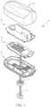
- the antenna assembly 25 preferably comprises a base 60, a modem 50, a top lid 40 and a housing 30.
- the antenna assembly comprises a base 60, a modem 50, router (not shown), a top lid 40 and a housing 30.
- the base 60 is preferably composed of an aluminum material.
- the modem 50 is disposed on the base 60.
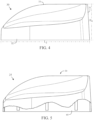
- the top lid 40 is to cover the base 60 and modem 50, and the top lid 40 preferably comprises at least one antenna element disposed on an exterior surface.
- a radiofrequency cable 70 is attached to the modem 50 and secured to the base 60 by bolt 71.
- the housing 30 covers the top lid 40 and the base 60.
- the top lid 40 acts as an electro-magnetic barrier for the modem 50 to maintain the electro-magnetic signals inside of the base 60 to prevent interference with the antenna signals.
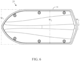
- the base 60 includes a body 61 with an interior surface 62.
- a side wall 63 defines an interior compartment 65 in which a first plurality of heat dissipation elements 66a-66e and a second plurality of heat dissipation elements 67a-67e.
- An aperture 64 extends through the body 61 for access by at least one cable.
- the base 60 is preferably composed of a die-cast aluminum material to prevent electro-magnetic signals from the modem 50 from interfering with the antennas on the top lid 40. In this manner, the modem 50 is capable of being placed in proximity to the antennas on the top lid 50 without interference from electro-magnetic signals with the antennas on the top lid 40.
- the first plurality of heat dissipation elements 66a-66e and the second plurality of heat dissipation elements 67a-67e dissipate heat that is generated by the operation of the modem 50.
- the top lid 40 comprises a first antenna element 42, a second antenna element 43 and a third antenna element 41.
- the first antenna element 42 is a multi-band antenna for cellular communications.
- the first antenna element is a 5G Sub 6GHz antenna or a mmWave antenna.
- the second antenna element 43 is selected from the group of antennas consisting of a WiFi 2G antenna, a WiFi 5G antenna, a DECT antenna, a ZigBee antenna, and a Zwave antenna.
- the WiFi 2G antennas are preferably 2400-2690 MegaHertz.
- the WiFi 5G antenna is preferably a 5.8 GigaHertz antenna.
- the second antenna element 43 operates at 5.15GHz or at 5.85GHz.
- Other possible frequencies for the second antenna element 43 include 5150MHz, 5200 MHz, 5300 MHz, 5400 MHz, 5500 MHz, 5600 MHz, 5700 MHz, 5850 MHz, and 2.4GHz.
- the second antenna element 43 preferably operates on an 802.11 communication protocol.
- the second antenna element 43 operates on an 802.11n communication protocol.
- the second antenna element 43 operates on an 802.11b communication protocol.
- the second antenna element 43 operates on an 802.1 lg communication protocol.
- the second antenna element 43 operates on an 802.11a communication protocol.
- the second antenna element 43 operates on an 802.1 lac communication protocol.
- first antenna element 42 the second antenna element 43 and/or the third antenna element 41 without departing from the scope of the present invention.
- other antenna types may be used for the first antenna element 42, the second antenna element 43 and/or the third antenna element 41 without departing from the scope of the present invention.
- the top lid 40 is preferably composed of an aluminum material, at least on a bottom surface.
- the top lid 40 is composed of materials that can act as a barrier to electro-magnetic signals.
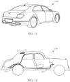
- FIG. 9 illustrates the removal of the existing antenna 900 of a vehicle, and the installation of an embodiment of antenna assembly 25 as described herein.
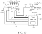
- FIGS. 10-12 illustrate the connections between the antenna assembly and the existing router 125 of the vehicle 1100.
- the antenna assembly 25 preferably comprises a base 60, a modem 50, a CPU 51, a combiner 92, a power regulator 94, and a plurality of antenna elements 31,32, 43 and 44 within a housing 30.
- Four coaxial cables 131, 132, 133 and 135 are connected from the antenna assembly 25 to connectors on the vehicle.
- the coaxial cable 135 is connected to an injector 105, the coaxial cables 132 and 133 are connected to WiFi connectors 161 and 162 of a router 125.
- the coaxial cable 131 is connected to a GPS/GNSS connector 160 of the router 125.
- the injector 105 comprises a reset button 95, a SIM card 96, a USB connection 97 and a power-conditioning unit.
- the router 125 preferably comprises a modem 130, an Ethernet or USB WAN connector 170, LTE connectors 163 and 164, an ignition sense and 12Volt connector 171 which an ignition sense cable 185 and 12Volt cable 190 connect thereto.
- installation is quicker and a lower risk (no static discharge accidental damage to the router or modem due to opening the router).
- Signal loss is typically higher at 5G mid-band frequencies than traditional cellular, and those losses are mitigated if not eliminated by the present invention.
- Using the modem that is embedded in the antenna housing avoids cable loss and thereby extends coverage range.
- the combiner 92 preferably inputs a wide area network connection from the router for send and receive data to/from Internet, and an ignition sense to put the unit to sleep and draw minimal power when the ignition is off.
- the combiner 92 also inputs twelve volts to power the antenna assembly 25, which allows the combiner 92 to perform power regulation and surge protection, and pass the power up to the modem 50 in the antenna housing 60.
- the combiner 92 also inputs a SIM card for a carrier (AT&T, Verizon, etc.) subscriber identity module remoted from the modem 50 so that it can be easily accessed in the trunk of the vehicle 1100. All of the above are combined and sent up to the antenna assembly 25 over the existing coaxial cable, or over the Ethernet plus other wires.
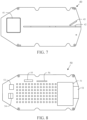
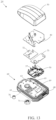
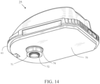
- FIGS. 13 and 14 illustrate thermal dissipation and isolation features that are utilized in certain embodiments of an antenna assembly 25 for a vehicle to optimize heat removal and to protect certain heat sensitive components.
- the antenna assembly 25 preferably comprises a housing 30, a top lid 40 with antenna elements and a base 60.
- the base 60 preferably has a body 61 and a heat sink 68, but those skilled in the pertinent art will recognize that the base may take various other forms without departing from the scope of the present invention.
- the body 61 preferably has a structure that forms a mounting surface 65 for some, or all, of the rest of the components of the antenna assembly 25.
- the body 61 has an internal compartment or recess 65 forming a mounting surface 69 for mounting certain components directly on the body 61 itself, while other components are mounted on other features that themselves are mounted to the body 61.
- the recess 65 has a shape that allows components to be mounted in proximity to or in contact with the heat sink 68.
- the recess 65 is formed in a shape that allows components to contact the heat sink 68 in substantially different areas, thereby transmitting their respective generated heat to different parts of the heat sink 68, and minimizing the crossflow of heat from one component to another through the heat sink 68.
- a first area of the heat sink 68 is located on one side of the base 60 and a second area of the heat sink 68 is located on an opposing side of the base 60.
- a first area of the heat sink 68 is located on one side of the base 60
- a second area of the heat sink 68 is located on an opposing side of the base 60
- a third area of the heat sink 68 is located at a rear section of the base 60.
- the heat sink 68 may be partitioned into multiple areas without departing from the scope of the present invention.
- the heat sink 68 preferably comprises a plurality of heat dissipation elements.
- the heat dissipation elements are preferably fins or pins.
- the recess 65 is generally rectangular and has mounting surfaces such that one component is in contact with one side of the heat sink 68 formed by the recess 65 and heat from another component is directed to another side of the heat sink 68 formed by the recess.
- the component mounting surface 69 is preferably formed to mount multiple components that have different heat sensitivities and heat generating characteristics.
- a first component such as a modem 50
- a second component such as a high-power amplifier 57
- the first and second heat transfer plates are each made of material selected from the list consisting of copper, aluminum, graphite, carbon diamond, magnesium, gold, silver, aluminum nitride, silicon carbide, and zinc.
- slots are formed by molding, cutting or otherwise in the mounting surface 69, to impede the flow of heat from one component to another and encourage the heat flow through the heat sink 68.
- thermal insulation of the antenna assembly 25 from the vehicle 1100 is desired to prevent heat from the vehicle 1100 from transferring to the antenna assembly 25.
- each interface between the antenna assembly 25 and the vehicle 1100 is evaluated for thermal insulation.
- a thermally insulative pad 75 is added between the base 61 to reduce heat transmitted from the vehicle 1100 to the antenna assembly 25.
- the thermally insulative pad 75 is also water resistant to aid in the prevention of water intrusion around and under the antenna assembly 25.
- a thermally insulative washer 74 is installed between the mounting nut 71 and the vehicle 1100.
- a thermally insulative bushing 76 is installed between the threaded tube 72, through which the radiofrequency cable 70 is routed, that fastens with the mounting nut 71 and the vehicle 1100 to avoid heat transfer from the vehicle 1100.
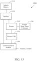
- a preferred embodiment of a system 1500 for activating and deactivating a communication module for an apparatus is utilized with a vehicle.
- the system 1500 includes battery 1510 (which can be any other type of power source), an ignition 1520 (or "on", or power switch), a router 1530, a router sleep timer 1540, a router USB 1550 (or other communications port or connection), and a communication module 1560.
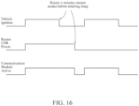
- the communication module 1560 preferably comprises one or more of the components of the antenna assemblies 25 in embodiments previously described herein. As shown in FIG. 16 , the communication module 1560 activates and deactivates in relation to a power activity of the vehicle ignition 1520 and router 1530.
- the communication module 1560 receives vehicle power and ignition 1510 inputs.
- the power is obvious in purpose.
- the ignition 1520 input wakes the communication module 1560 from a low power sleep mode so that it does not drain the vehicle when the ignition 1520 is off.
- Another input to the communication module 1560 connects to the vehicle router 1530 (such as via the +5Vdc pin) on the vehicle router's 1530 USB connector 1550.
- the normal function of the USB port 1550 on the router 1530 is to connect an accessory like an external modem (not separately shown).
- the present embodiment uses the USB port 1550 to sense when the router 1530 is asleep or awake.
- the communication module 1560 logically utilizes an "OR" function for comparing router 1530 sleep sense with ignition 1520 sense. The output of the OR controls when the communication module 1560 sleeps (deactivates). If the ignition 1520 is on or the router 1530 is on, the communication module 1560 is on.
- the router 1530 is configured to enter sleep mode after a predetermined time period after the ignition 1520 sense goes off.
- the system 1500 matches the communication module's 1560 sleep pattern to the router's 1530 sleep pattern.
- the communication module's 1560 sleep pattern overlaps the router's 1530 sleep pattern to extend beyond the period of the router's 1530 sleep setting timeout to ensure the communication module 1560 remains active beyond the period at which the router 1530 powers down.
- the communication module 1560 determines if the router 1530 is powered up (awake) or powered down (sleep).
- the communication module 1560 senses the USB port 1550 power to make a determination when to power down (sleep). If the ignition 1520 is off and the USB port 1550 transitions from powered up to powered down, the communication module 1560 will power down (sleep). Any time the USB port 1550 is powered up, the communication module 1560 is powered up. By following the router's 1530 sleep state, the communication module 1560 provides mobile network connectivity whenever the router 1530 needs it. The communication module 1560 similarly senses the vehicle ignition 1520 state. Anytime the ignition 1520 is on, the communication module 1560 is on. By powering up immediately upon the vehicle ignition 1520 coming on, the communication module 1560 rapidly awakens and goes into service before the router 1530 awakens.
- This is logically an OR function. If either the router USB port 1550 is powered on, OR the vehicle ignition 1520 is powered on, then the communication module 1560 is powered up and awake.
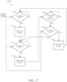
- FIG. 17 is a flow chart for a process 1700 for activating and deactivating a communication module 1560 in a communication system 1500 utilizing a router 1530 sleep timer.
- an inquiry is made if the ignition 1520 is on. If Yes, the process 1700 moves to process state 1710 the router 1530 is powered up.
- an inquiry is made if the ignition 1520 is on. If No, the process 1700 proceeds to process state 1720 and the start sleep timer commences.
- decision state 1725 an inquiry is made if the sleep time has expired. If Yes, the process 1500 moves to decision state 1730 where an inquiry is made if the ignition 1520 is on. If No, at the process 1700 proceeds to process state 1735, and the router 1530 is powered off.
Landscapes
- Engineering & Computer Science (AREA)
- Computer Networks & Wireless Communication (AREA)
- Signal Processing (AREA)
- Remote Sensing (AREA)
- Transceivers (AREA)
- Details Of Aerials (AREA)
Claims (9)
- Antennenbaugruppe (25) für ein Fahrzeug (1100), wobei die Antennenbaugruppe (25) Folgendes umfasst:eine Basis (60), die eine innere Oberfläche (62), eine Seitenwand (63) und eine Vielzahl von Wärmeabführungselementen (66a-66e, 67a-67e), die von der Seitenwand (63) nach außen gerichtet sind, umfasst;ein Modem (50), das innerhalb der Basis (60) positioniert ist;eine Antennenplatine, die innerhalb der Basis (60) positioniert ist und eine Vielzahl von Antennenelementen (41, 42, 43) umfasst;ein Gehäuse (30) zum Abdecken der Basis (60); undeinen Ruhemoduserfassungsbefehl, der konfiguriert ist, um die Antennenbaugruppe (25) aus einem energiesparenden Ruhemodus zu aktivieren, wenn eine Eingabe einer Zündung (1520) des Fahrzeugs (1100) durch die Antennenbaugruppe (25) empfangen wird oder wenn eine Spannung eines Fahrzeugeinrichtungs-USB-Anschlusses (1550) durch die Antennenbaugruppe (25) empfangen wird.
- Antennenbaugruppe (25) nach Anspruch 1, wobei die Vielzahl von Antennenelementen (41, 42, 43) mindestens ein LTE-Antennenelement, mindestens ein WiFi-Antennenelement und mindestens ein GPS/GNSS-Antennenelement umfasst.
- Antennenbaugruppe (25) nach Anspruch 1, wobei die Fahrzeugeinrichtung ein interner Fahrzeugrouter (1530) ist.
- Antennenbaugruppe (25) nach Anspruch 1, die ferner ein Kommunikationskabel umfasst, das an einem Ende mit dem Modem (50) verbunden ist und sich an einem anderen Ende zu der Fahrzeugeinrichtung hin erstreckt und mit dieser verbunden ist.
- Antennenbaugruppe (25) nach Anspruch 1, wobei die Vielzahl von Wärmeabführungselementen (66a-66e, 67a-67e) eine Vielzahl von Stufenoberflächen, die sich von der Seitenwand (63) nach außen erstrecken, umfasst.
- Antennenbaugruppe (25) nach Anspruch 1, die ferner ein Wärmeisolierpad umfasst, das an einer unteren Oberfläche der Basis (60) angebracht ist.
- Antennenbaugruppe (25) nach Anspruch 1, wobei der Ruhemoduserfassungsbefehl mit einem Energiemodus der Fahrzeugeinrichtung synchronisiert wird.
- Verfahren zum Aktivieren und Deaktivieren eines Modems (50) der Antennenbaugruppe (25) nach einem der Ansprüche 1 bis 7, wobei das Verfahren Folgendes umfasst:Empfangen eines Aktivierungssignals an einem Prozessor aus einer Eingabe einer Zündung (1520) des Fahrzeugs (1100) oder einer Spannung eines Fahrzeugeinrichtungs-USB-Anschlusses (1550), wenn das Modem (50) der Antennenbaugruppe (25) in einem energiesparenden Ruhemodus ist; undAktivieren des Modems (50) aus dem energiesparenden Ruhemodus.
- Verfahren nach Anspruch 8, das ferner das Empfangen eines eingegebenen Deaktivierungssignals an dem Prozessor aus der Eingabe der Zündung (1520) des Fahrzeugs (1100) und der Spannung des Router-USB-Anschlusses (1550) und das Deaktivieren des Modems (50) in den energiesparenden Ruhemodus umfasst.
Applications Claiming Priority (2)
| Application Number | Priority Date | Filing Date | Title |
|---|---|---|---|
| US202063009989P | 2020-04-14 | 2020-04-14 | |
| PCT/US2021/026757 WO2021211388A1 (en) | 2020-04-14 | 2021-04-11 | Antenna assembly for a vehicle |
Publications (3)
| Publication Number | Publication Date |
|---|---|
| EP4136757A1 EP4136757A1 (de) | 2023-02-22 |
| EP4136757B1 true EP4136757B1 (de) | 2025-07-02 |
| EP4136757C0 EP4136757C0 (de) | 2025-07-02 |
Family
ID=75660430
Family Applications (1)
| Application Number | Title | Priority Date | Filing Date |
|---|---|---|---|
| EP21721375.0A Active EP4136757B1 (de) | 2020-04-14 | 2021-04-11 | Antennenanordnung für ein fahrzeug |
Country Status (6)
| Country | Link |
|---|---|
| EP (1) | EP4136757B1 (de) |
| JP (1) | JP2023521891A (de) |
| KR (1) | KR20230002616A (de) |
| CN (1) | CN115699589A (de) |
| TW (1) | TW202143549A (de) |
| WO (1) | WO2021211388A1 (de) |
Family Cites Families (9)
| Publication number | Priority date | Publication date | Assignee | Title |
|---|---|---|---|---|
| US4901307A (en) | 1986-10-17 | 1990-02-13 | Qualcomm, Inc. | Spread spectrum multiple access communication system using satellite or terrestrial repeaters |
| US6028537A (en) * | 1996-06-14 | 2000-02-22 | Prince Corporation | Vehicle communication and remote control system |
| US20090231186A1 (en) * | 2008-02-06 | 2009-09-17 | Raysat Broadcasting Corp. | Compact electronically-steerable mobile satellite antenna system |
| CN102547935B (zh) * | 2011-12-23 | 2015-08-19 | 华为终端有限公司 | 一种控制便携式路由器低功耗工作的方法及便携式路由器 |
| US9754431B2 (en) * | 2014-08-18 | 2017-09-05 | Livio, Inc. | Method and system for a key fob base station enabling remote car access using a nomadic device |
| WO2017076750A1 (en) * | 2015-11-02 | 2017-05-11 | Taoglas Limited | A multi-network telematics device with multiple antennas |
| CN106851797A (zh) * | 2016-12-16 | 2017-06-13 | 上海斐讯数据通信技术有限公司 | 可无线唤醒路由器、无线唤醒系统及路由器无线唤醒方法 |
| US10741932B2 (en) * | 2017-09-30 | 2020-08-11 | Intel IP Corporation | Compact radio frequency (RF) communication modules with endfire and broadside antennas |
| US10931325B2 (en) * | 2019-01-01 | 2021-02-23 | Airgain, Inc. | Antenna assembly for a vehicle |
-
2021
- 2021-04-11 EP EP21721375.0A patent/EP4136757B1/de active Active
- 2021-04-11 KR KR1020227039243A patent/KR20230002616A/ko not_active Withdrawn
- 2021-04-11 CN CN202180040205.0A patent/CN115699589A/zh active Pending
- 2021-04-11 JP JP2022562679A patent/JP2023521891A/ja active Pending
- 2021-04-11 WO PCT/US2021/026757 patent/WO2021211388A1/en not_active Ceased
- 2021-04-13 TW TW110113167A patent/TW202143549A/zh unknown
Also Published As
| Publication number | Publication date |
|---|---|
| EP4136757A1 (de) | 2023-02-22 |
| KR20230002616A (ko) | 2023-01-05 |
| EP4136757C0 (de) | 2025-07-02 |
| WO2021211388A1 (en) | 2021-10-21 |
| CN115699589A (zh) | 2023-02-03 |
| TW202143549A (zh) | 2021-11-16 |
| JP2023521891A (ja) | 2023-05-25 |
Similar Documents
| Publication | Publication Date | Title |
|---|---|---|
| EP3824558B1 (de) | Antennenanordnung für ein fahrzeug | |
| US12113273B2 (en) | Antenna assembly for a vehicle with sleep sense command | |
| US12113267B2 (en) | Antenna assembly for a vehicle | |
| US10601124B1 (en) | Antenna assembly for a vehicle | |
| EP4136702B1 (de) | Antennenanordnung für ein fahrzeug | |
| EP4136757B1 (de) | Antennenanordnung für ein fahrzeug | |
| CA3113570C (en) | Antenna assembly for a vehicle | |
| HK40087837A (zh) | 用於车辆的天线组件 | |
| HK40089801A (zh) | 用於车辆的天线组件 | |
| KR100612052B1 (ko) | 휴대 단말기용 내장형 안테나 |
Legal Events
| Date | Code | Title | Description |
|---|---|---|---|
| STAA | Information on the status of an ep patent application or granted ep patent |
Free format text: STATUS: UNKNOWN |
|
| STAA | Information on the status of an ep patent application or granted ep patent |
Free format text: STATUS: THE INTERNATIONAL PUBLICATION HAS BEEN MADE |
|
| PUAI | Public reference made under article 153(3) epc to a published international application that has entered the european phase |
Free format text: ORIGINAL CODE: 0009012 |
|
| STAA | Information on the status of an ep patent application or granted ep patent |
Free format text: STATUS: REQUEST FOR EXAMINATION WAS MADE |
|
| 17P | Request for examination filed |
Effective date: 20221101 |
|
| AK | Designated contracting states |
Kind code of ref document: A1 Designated state(s): AL AT BE BG CH CY CZ DE DK EE ES FI FR GB GR HR HU IE IS IT LI LT LU LV MC MK MT NL NO PL PT RO RS SE SI SK SM TR |
|
| DAV | Request for validation of the european patent (deleted) | ||
| DAX | Request for extension of the european patent (deleted) | ||
| GRAP | Despatch of communication of intention to grant a patent |
Free format text: ORIGINAL CODE: EPIDOSNIGR1 |
|
| STAA | Information on the status of an ep patent application or granted ep patent |
Free format text: STATUS: GRANT OF PATENT IS INTENDED |
|
| RIC1 | Information provided on ipc code assigned before grant |
Ipc: H04W 52/02 20090101ALN20250228BHEP Ipc: H01Q 21/28 20060101ALI20250228BHEP Ipc: H01Q 1/02 20060101ALI20250228BHEP Ipc: H01Q 1/32 20060101ALI20250228BHEP Ipc: H04B 1/3822 20150101ALI20250228BHEP Ipc: H04B 1/036 20060101AFI20250228BHEP |
|
| INTG | Intention to grant announced |
Effective date: 20250408 |
|
| GRAS | Grant fee paid |
Free format text: ORIGINAL CODE: EPIDOSNIGR3 |
|
| GRAA | (expected) grant |
Free format text: ORIGINAL CODE: 0009210 |
|
| STAA | Information on the status of an ep patent application or granted ep patent |
Free format text: STATUS: THE PATENT HAS BEEN GRANTED |
|
| AK | Designated contracting states |
Kind code of ref document: B1 Designated state(s): AL AT BE BG CH CY CZ DE DK EE ES FI FR GB GR HR HU IE IS IT LI LT LU LV MC MK MT NL NO PL PT RO RS SE SI SK SM TR |
|
| REG | Reference to a national code |
Ref country code: GB Ref legal event code: FG4D |
|
| REG | Reference to a national code |
Ref country code: CH Ref legal event code: EP |
|
| REG | Reference to a national code |
Ref country code: IE Ref legal event code: FG4D |
|
| U01 | Request for unitary effect filed |
Effective date: 20250707 |
|
| U07 | Unitary effect registered |
Designated state(s): AT BE BG DE DK EE FI FR IT LT LU LV MT NL PT RO SE SI Effective date: 20250711 |
|
| PG25 | Lapsed in a contracting state [announced via postgrant information from national office to epo] |
Ref country code: IS Free format text: LAPSE BECAUSE OF FAILURE TO SUBMIT A TRANSLATION OF THE DESCRIPTION OR TO PAY THE FEE WITHIN THE PRESCRIBED TIME-LIMIT Effective date: 20251102 |
|
| PG25 | Lapsed in a contracting state [announced via postgrant information from national office to epo] |
Ref country code: NO Free format text: LAPSE BECAUSE OF FAILURE TO SUBMIT A TRANSLATION OF THE DESCRIPTION OR TO PAY THE FEE WITHIN THE PRESCRIBED TIME-LIMIT Effective date: 20251002 |
|
| PG25 | Lapsed in a contracting state [announced via postgrant information from national office to epo] |
Ref country code: HR Free format text: LAPSE BECAUSE OF FAILURE TO SUBMIT A TRANSLATION OF THE DESCRIPTION OR TO PAY THE FEE WITHIN THE PRESCRIBED TIME-LIMIT Effective date: 20250702 |
|
| PG25 | Lapsed in a contracting state [announced via postgrant information from national office to epo] |
Ref country code: GR Free format text: LAPSE BECAUSE OF FAILURE TO SUBMIT A TRANSLATION OF THE DESCRIPTION OR TO PAY THE FEE WITHIN THE PRESCRIBED TIME-LIMIT Effective date: 20251003 |
|
| PG25 | Lapsed in a contracting state [announced via postgrant information from national office to epo] |
Ref country code: CZ Free format text: LAPSE BECAUSE OF FAILURE TO SUBMIT A TRANSLATION OF THE DESCRIPTION OR TO PAY THE FEE WITHIN THE PRESCRIBED TIME-LIMIT Effective date: 20250702 |
|
| PG25 | Lapsed in a contracting state [announced via postgrant information from national office to epo] |
Ref country code: PL Free format text: LAPSE BECAUSE OF FAILURE TO SUBMIT A TRANSLATION OF THE DESCRIPTION OR TO PAY THE FEE WITHIN THE PRESCRIBED TIME-LIMIT Effective date: 20250702 |
|
| PG25 | Lapsed in a contracting state [announced via postgrant information from national office to epo] |
Ref country code: RS Free format text: LAPSE BECAUSE OF FAILURE TO SUBMIT A TRANSLATION OF THE DESCRIPTION OR TO PAY THE FEE WITHIN THE PRESCRIBED TIME-LIMIT Effective date: 20251002 |
|
| PG25 | Lapsed in a contracting state [announced via postgrant information from national office to epo] |
Ref country code: ES Free format text: LAPSE BECAUSE OF FAILURE TO SUBMIT A TRANSLATION OF THE DESCRIPTION OR TO PAY THE FEE WITHIN THE PRESCRIBED TIME-LIMIT Effective date: 20250702 |
|
| PG25 | Lapsed in a contracting state [announced via postgrant information from national office to epo] |
Ref country code: SM Free format text: LAPSE BECAUSE OF FAILURE TO SUBMIT A TRANSLATION OF THE DESCRIPTION OR TO PAY THE FEE WITHIN THE PRESCRIBED TIME-LIMIT Effective date: 20250702 |
|
| PGFP | Annual fee paid to national office [announced via postgrant information from national office to epo] |
Ref country code: SE Payment date: 20260312 Year of fee payment: 6 |
|
| PGFP | Annual fee paid to national office [announced via postgrant information from national office to epo] |
Ref country code: GB Payment date: 20260313 Year of fee payment: 6 |
|
| PGFP | Annual fee paid to national office [announced via postgrant information from national office to epo] |
Ref country code: MC Payment date: 20260325 Year of fee payment: 6 |
|
| PGFP | Annual fee paid to national office [announced via postgrant information from national office to epo] |
Ref country code: IE Payment date: 20260310 Year of fee payment: 6 |