EP4136702B1 - Antennenanordnung für ein fahrzeug - Google Patents
Antennenanordnung für ein fahrzeug Download PDFInfo
- Publication number
- EP4136702B1 EP4136702B1 EP21721374.3A EP21721374A EP4136702B1 EP 4136702 B1 EP4136702 B1 EP 4136702B1 EP 21721374 A EP21721374 A EP 21721374A EP 4136702 B1 EP4136702 B1 EP 4136702B1
- Authority
- EP
- European Patent Office
- Prior art keywords
- heat
- modem
- vehicle
- antenna
- antenna assembly
- Prior art date
- Legal status (The legal status is an assumption and is not a legal conclusion. Google has not performed a legal analysis and makes no representation as to the accuracy of the status listed.)
- Active
Links
Images


Classifications
-
- H—ELECTRICITY
- H01—ELECTRIC ELEMENTS
- H01Q—ANTENNAS, i.e. RADIO AERIALS
- H01Q1/00—Details of, or arrangements associated with, antennas
- H01Q1/02—Arrangements for de-icing; Arrangements for drying-out ; Arrangements for cooling; Arrangements for preventing corrosion
-
- H—ELECTRICITY
- H01—ELECTRIC ELEMENTS
- H01Q—ANTENNAS, i.e. RADIO AERIALS
- H01Q1/00—Details of, or arrangements associated with, antennas
- H01Q1/27—Adaptation for use in or on movable bodies
- H01Q1/32—Adaptation for use in or on road or rail vehicles
- H01Q1/325—Adaptation for use in or on road or rail vehicles characterised by the location of the antenna on the vehicle
- H01Q1/3275—Adaptation for use in or on road or rail vehicles characterised by the location of the antenna on the vehicle mounted on a horizontal surface of the vehicle, e.g. on roof, hood, trunk
Definitions
- This invention generally relates to antenna assemblies for vehicles, and more specifically to a heat dissipation system for an antenna assembly for a vehicle.
- a modem for the vehicle In wireless communication systems for vehicles, a modem for the vehicle is typically placed a great distance away from an antenna in order to prevent electro-magnetic signals from the modem from interfering with the antenna. This often requires a long coaxial cable wired throughout the vehicle.
- BLUETOOTH technology is a standard short range radio link that operates in the unlicensed 2.4 gigahertz band.
- CDMA Code Division Multiple Access
- GSM Global System for Mobile Communications
- GSM Global System for Mobile Communications
- the Universal Mobile Telecommunications System (“UMTS”) is a wireless standard.
- LTE Long Term Evolution
- LTE Frequency Bands include 698-798MHz (Band 12, 13, 14, 17); 791-960MHz (Band 5, 6, 8, 18,19,20); 1710-2170MHz (Band 1, 2, 3, 4, 9, 10, 23, 25, 33, 34, 35, 36, 37, 39); 1427-1660.5MH (Band 11, 21, 24); 2300-2700MHz (Band 7, 38, 40, 41); 3400-3800MHz (Band 22, 42, 43).
- Antenna impedance and the quality of the impedance match are most commonly characterized by either return loss or Voltage Standing Wave Ratio.
- SMT Surface Mount Technology
- the APPLE IPHONE 5 LTE Bands include: LTE700 /1700/2100 (698-806MHz/1710-1785MHz/1920-2170MHz); LTE 850/1800/2100 (824-894MHz/1710-1880MHz/1920-2170MHz); and LTE 700/850/1800/1900/2100 (698-806MHz/824-894MHz/1710-1880MHz/1850-1990MHz/1920/2170).
- the SAMSUNG GALAXY ® SIii LTE Bands include: LTE 800/1800/2600 (806-869MHz/1710-1880MHz/2496-2690MHz.
- the NOKIA LUMIA ® 920 LTE Bands LTE 700/1700/2100 (698-806MHz/1710-1785MHz/1920-2170MHz); LTE 800/900/1800/2100/2600 (806-869MHz/880-960MHz/1710-1880MHz/1920-2170MHz/2496-2690MHz).
- the long coaxial cable that connects a modem to an antenna on a vehicle leads to signal losses due to the length of the coaxial cable.
- Prior art document US 2019/312342 A1 discloses a communication system, comprising at least one housing having a first and an additional housing part.
- a circuit board having electronic components is arranged, and outside the housing, at least one antenna element is arranged.
- the invention is characterized in that an antenna support that is connectable to the housing is provided, wherein the at least one antenna element is arranged on the surface and/or inside the antenna support.
- the component is placed in line with the metal screen and in thermal contact with a portion of said screen, and said screen is made of a thermally conductive material so as to form a thermal transfer means between the electronic power component and the metal part.
- a satellite antenna terminal includes a circuit board having first and second opposite surfaces.
- a plurality of antenna elements are disposed on the first surface of the circuit board and are operative to receive Radio Frequency (RF) signals from a satellite.
- RF Radio Frequency
- One or more signal processing devices are disposed on the second surface of the circuit board and are coupled to process the RF signals received by the antenna elements.
- One aspect of the present invention is a heat dissipation system according to claim 1.
- the present invention eliminates the signal loss over the cables connecting the modem to the antenna since the modem and antenna are in relative proximity.
- the present invention also replaces several coaxial cables with a single cable.
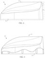
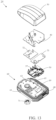
- the antenna assembly 25 preferably comprises a base 60, a modem 50, a top lid 40 and a housing 30.
- the antenna assembly comprises a base 60, a modem 50, router (not shown), a top lid 40 and a housing 30.
- the base 60 is preferably composed of an aluminum material.
- the modem 50 is disposed on the base 60.
- the top lid 40 is to cover the base 60 and modem 50, and the top lid 40 preferably comprises at least one antenna element disposed on an exterior surface.
- a radiofrequency cable 70 is attached to the modem 50 and secured to the base 60 by bolt 71.
- the housing 30 covers the top lid 40 and the base 60.
- the top lid 40 acts as an electro-magnetic barrier for the modem 50 to maintain the electro-magnetic signals inside of the base 60 to prevent interference with the antenna signals.
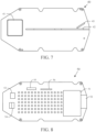
- the base 60 includes a body 61 with an interior surface 62.
- a side wall 63 defines an interior compartment 65 in which a first plurality of heat dissipation elements 66a-66e and a second plurality of heat dissipation elements 67a-67e.
- An aperture 64 extends through the body 61 for access by at least one cable.
- the base 60 is preferably composed of a die-cast aluminum material to prevent electro-magnetic signals from the modem 50 from interfering with the antennas on the top lid 40. In this manner, the modem 50 is capable of being placed in proximity to the antennas on the top lid 50 without interference from electro-magnetic signals with the antennas on the top lid 40.
- the first plurality of heat dissipation elements 66a-66e and the second plurality of heat dissipation elements 67a-67e dissipate heat that is generated by the operation of the modem 50.
- the sidewall 63 in addition to acting as electro-magnetic barrier, also provides a structure for placement of the top lid 40 thereon.
- the base 60 preferably has a height H2 ranging from 0.5 inch to 1.0 inch, a height, H1, ranging from 0.05 inch to 0.15 inch, and a height, H3, ranging from 0.15 inch to 0.30 inch
- the base preferably has a width ranging from 2.5 inches to 3.5 inches, and a length, L1, ranging from 6.0 inches to 8.0 inches.
- the aperture 64 is preferably from 1.0 inch to 1.25 inches across.
- the top lid 40 comprises a first antenna element 42, a second antenna element 43 and a third antenna element 41.
- the first antenna element 42 is a multi-band antenna for cellular communications.
- the first antenna element is a 5G Sub 6GHz antenna or a mmWave antenna.
- the second antenna element 43 is selected from the group of antennas consisting of a WiFi 2G antenna, a WiFi 5G antenna, a DECT antenna, a ZigBee antenna, and a Zwave antenna.
- the WiFi 2G antennas are preferably 2400-2690 MegaHertz.
- the WiFi 5G antenna is preferably a 5.8 GigaHertz antenna.
- the second antenna element 43 operates at 5.15GHz or at 5.85GHz.
- Other possible frequencies for the second antenna element 43 include 5150MHz, 5200 MHz, 5300 MHz, 5400 MHz, 5500 MHz, 5600 MHz, 5700 MHz, 5850 MHz, and 2.4GHz.
- the second antenna element 43 preferably operates on an 802.11 communication protocol.
- the second antenna element 43 operates on an 802.11n communication protocol.
- the second antenna element 43 operates on an 802.11b communication protocol.
- the second antenna element 43 operates on an 802.11g communication protocol.
- the second antenna element 43 operates on an 802.11a communication protocol.
- the second antenna element 43 operates on an 802.11ac communication protocol.
- the third antenna element 41 is preferably a GPS/GLONASS module.
- first antenna element 42 the second antenna element 43 and/or the third antenna element 41 without departing from the scope of the present invention.
- other antenna types may be used for the first antenna element 42, the second antenna element 43 and/or the third antenna element 41 without departing from the scope of the present invention.
- the top lid 40 is preferably composed of an aluminum material, at least on a bottom surface.
- the top lid 40 is composed of materials that can act as a barrier to electro-magnetic signals.
- the modem 50 preferably includes at least one of a computation component, a communication chip 55, a switch, an antenna switch circuit, a GNSS reception component 56, a security access module 53, a mobile phone communication component 54, and a power supply source.
- the computation component preferably includes a CPU 51, a memory 52, and an interface (I/F) component.
- the modem 50 preferably operates for cellular protocols including 3G, 4G, 4G HPUE and 5G technology.
- HPUE is High Power User Equipment, and is more specifically a special class of user equipment for a cellular network, such as a LTE cellular network.
- the housing 30 is composed of a polypropylene material. As shown in FIGS. 4, 5 and 6 , the housing 30 preferably has a height, H4, ranging from 50 to 90 millimeters (mm), more preferably from 60 to 80mm, and most preferably from 65 to 75mm.
- the housing 30 preferably has a length, L2, ranging from 100 to 250mm, more preferably from 150 to 200mm, and most preferably from 160 to 190mm.
- the housing 30 preferably has a width, W1 ranging from 50 to 100mm, more preferably from 60 to 90mm, and most preferably from 65 to 85mm.
- An internal width W2 is preferably 70 to 80mm.
- a width W3 is preferably 10 to 15mm.
- the housing 30 has a sidewall 32, a crown 33 and a rear wall 31. The walls of the housing 30 preferably have a thickness ranging from 2 to 7mm, and most preferably are 5mm.
- FIGS. 9-12 Another embodiment of the invention is set forth in FIGS. 9-12 .
- the antenna assembly system is used as a remote modem plus an antenna plus a serial communication system for upgrading existing installed routers to 5G sub 6GHz, or adding a failover modem.
- a technician To upgrade an existing router to 5G with a new internal modem, a technician must: remove the router from the vehicle; take the router apart to remove the modem; install a new modem; install the router in the vehicle; and test the router to verify the new modem is working properly.
- a technician To upgrade an existing router to 5G using an antenna assembly of the present invention, a technician must, leveraging the already-installed coax cables (as shown in FIG. 9 ): loosen the existing antenna on a vehicle roof; cut the coax cables; add a coax connector to two of the cables; use one coax cable for powering the antenna assembly and for serial Ethernet communications; use the second coax cable for GPS/GNSS; connect a coax-to-Ethernet combiner and power injector to the router's spare Ethernet WAN port to 12V power (it combines Ethernet and power and conveys them over coax) and to an ignition sense; configure the router to use the Ethernet port as the WAN if it is not already configured; test the router to verify it is communicating over the new modem; remove the existing antenna and cables; disconnect the coax cables from the router; remove the antenna from the roof of the vehicle; install the new antenna and connect the coax cables to the router; connect the injector module to the router Ethernet, vehicle power and
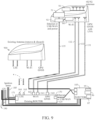
- FIG. 9 illustrates the removal of the existing antenna 900 of a vehicle, and the installation of an embodiment of antenna assembly 25 as described herein.
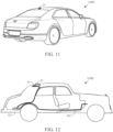
- FIGS. 10-12 illustrate the connections between the antenna assembly and the existing router 125 of the vehicle 1100.
- the antenna assembly 25 preferably comprises a base 60, a modem 50, a CPU 51, a combiner 92, a power regulator 94, and a plurality of antenna elements 31,32, 43 and 44 within a housing 30.
- Four coaxial cables 131, 132, 133 and 135 are connected from the antenna assembly 25 to connectors on the vehicle.
- the coaxial cable 135 is connected to an injector 105, the coaxial cables 132 and 133 are connected to WiFi connectors 161 and 162 of a router 125.
- the coaxial cable 131 is connected to a GPS/GNSS connector 160 of the router 125.
- the injector 105 comprises a reset button 95, a SIM card 96, a USB connection 97 and a power-conditioning unit.
- the router 125 preferably comprises a modem 130, an Ethernet or USB WAN connector 170, LTE connectors 163 and 164, an ignition sense and 12Volt connector 171 which an ignition sense cable 185 and 12Volt cable 190 connect thereto.
- installation is quicker and a lower risk (no static discharge accidental damage to the router or modem due to opening the router).
- Signal loss is typically higher at 5G mid-band frequencies than traditional cellular, and those losses are mitigated if not eliminated by the present invention.
- Using the modem that is embedded in the antenna housing avoids cable loss and thereby extends coverage range.
- a user of certain embodiments of antenna assemblies described herein can continue to use the software they have been using with their existing router.
- the combiner 92 preferably inputs a wide area network connection from the router for send and receive data to/from Internet, and an ignition sense to put the unit to sleep and draw minimal power when the ignition is off.
- the combiner 92 also inputs twelve volts to power the antenna assembly 25, which allows the combiner 92 to perform power regulation and surge protection, and pass the power up to the modem 50 in the antenna housing 60.
- the combiner 92 also inputs a SIM card for a carrier (AT&T, Verizon, etc.) subscriber identity module remoted from the modem 50 so that it can be easily accessed in the trunk of the vehicle 1100. All of the above are combined and sent up to the antenna assembly 25 over the existing coaxial cable, or over the Ethernet plus other wires.
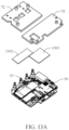
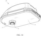
- FIGS. 13 , 13A and 14 illustrate thermal dissipation and isolation features that are utilized in certain embodiments of an antenna assembly 25 for a vehicle to optimize heat removal and to protect certain heat sensitive components.
- the antenna assembly 25 preferably comprises a housing 30, a top lid 40 with antenna elements and a base 60.
- the base 60 preferably has a body 61 and a heat sink 68, but those skilled in the pertinent art will recognize that the base may take various other forms without departing from the scope of the present invention.
- the body 61 preferably has a structure that forms a mounting surface 65 for some, or all, of the rest of the components of the antenna assembly 25.
- the body 61 has an internal compartment or recess 65 forming a mounting surface 69 for mounting certain components directly on the body 61 itself, while other components are mounted on other features that themselves are mounted to the body 61.
- the recess 65 has a shape that allows components to be mounted in proximity to or in contact with the heat sink 68.
- the recess 65 is formed in a shape that allows components to contact the heat sink 68 in substantially different areas, thereby transmitting their respective generated heat to different parts of the heat sink 68, and minimizing the crossflow of heat from one component to another through the heat sink 68.
- a first area of the heat sink 68 is located on one side of the base 60 and a second area of the heat sink 68 is located on an opposing side of the base 60.
- a first area of the heat sink 68 is located on one side of the base 60
- a second area of the heat sink 68 is located on an opposing side of the base 60
- a third area of the heat sink 68 is located at a rear section of the base 60.
- the heat sink 68 may be partitioned into multiple areas without departing from the scope of the present invention.
- the heat sink 68 preferably comprises a plurality of heat dissipation elements.
- the heat dissipation elements are preferably fins or pins.
- the recess 65 is generally rectangular and has mounting surfaces such that one component is in contact with one side of the heat sink 68 formed by the recess 65 and heat from another component is directed to another side of the heat sink 68 formed by the recess.
- the component mounting surface 69 is preferably formed to mount multiple components that have different heat sensitivities and heat generating characteristics.
- a first component such as a modem 50
- a second component such as a high-power amplifier 57
- heat transfer plates 72, 73 are attached to the body 61 or heat sink 68 and in thermal contact with the components mounted on the body 61.
- the heat transfer plates 72, 73 are preferably mounted directly on the components (e.g., modem 50 and high-power amplifier 57) or alternatively in thermal contact with the components via thermally conductive materials 1302 and 1303 (as shown in FIG. 13A ).
- the heat transfer plates 72, 73 of in these embodiments are mounted directly or via fasteners to the body 61 or the heat sink 68.
- the first and second heat transfer plates are each made of material selected from the list consisting of copper, aluminum, graphite, carbon diamond, magnesium, gold, silver, aluminum nitride, silicon carbide, and zinc.
- slots are formed by molding, cutting or otherwise in the mounting surface 69, to impede the flow of heat from one component to another and encourage the heat flow through the heat sink 68.
- thermal insulation of the antenna assembly 25 from the vehicle 1100 is desired to prevent heat from the vehicle 1100 from transferring to the antenna assembly 25.
- each interface between the antenna assembly 25 and the vehicle 1100 is evaluated for thermal insulation.
- a thermally insulative pad 75 is added between the base 61 to reduce heat transmitted from the vehicle 1100 to the antenna assembly 25.
- the thermally insulative pad 75 is also water resistant to aid in the prevention of water intrusion around and under the antenna assembly 25.
- a thermally insulative washer 74 is installed between the mounting nut 71 and the vehicle 1100.
- a thermally insulative bushing 76 is installed between the threaded tube 72, through which the radiofrequency cable 70 is routed, that fastens with the mounting nut 71 and the vehicle 1100 to avoid heat transfer from the vehicle 1100.
Landscapes
- Engineering & Computer Science (AREA)
- Remote Sensing (AREA)
- Details Of Aerials (AREA)
- Transceivers (AREA)
Claims (7)
- Wärmeableitungssystem, das eine Antennenbaugruppe (25) für ein Fahrzeug (1100) umfasst, wobei die Antennenbaugruppe (25) einen Verstärker (57), der während des Betriebs Wärme erzeugt, und ein Modem (50), das während des Betriebs Wärme erzeugt, aufweist, wobei das Wärmeableitungssystem Folgendes umfasst:eine Basis (60), die einen Körper (61) und eine Wärmesenke (68) umfasst, wobei die Wärmesenke (68) eine Vielzahl von Wärmeableitungselementen (66a-66e) umfasst und der Körper (61) eine Aussparung (65), die eine Komponentenmontageoberfläche (69) bildet, definiert;eine erste Wärmeübertragungsplatte (72) in thermischem Kontakt mit dem Verstärker (57);eine zweite Wärmeübertragungsplatte (73) in thermischem Kontakt mit dem Modem (50); undein wärmedämmendes Material, das zwischen dem Modem (50) und der Basis (60) angeordnet und dazu ausgebildet ist, die von dem Verstärker (57) an das Modem (50) übertragene Wärme zu minimieren;wobei das Modem (50) und der Verstärker (57) innerhalb der Aussparung (65) auf der Komponentenmontageoberfläche (69) angeordnet sind;wobei die erste Wärmeübertragungsplatte (72) in thermischem Kontakt mit einer ersten Fläche der Wärmesenke (68) ist und die zweite Übertragungsplatte (73) in thermischem Kontakt mit einer zweiten Fläche der Wärmesenke (68) ist, die von dem ersten Teil der Wärmesenke (68) getrennt ist.
- Wärmeableitungssystem nach Anspruch 1, das ferner ein wärmeleitendes Material (1302, 1303) umfasst, das zwischen dem Verstärker (57) und der ersten Wärmeübertragungsplatte (72) und zwischen dem Modem (50) und der zweiten Wärmeübertragungsplatte (73) angeordnet ist.
- Wärmeableitungssystem nach Anspruch 1, wobei der Verstärker (57) bei einem bestimmten Betriebszustand Wärme erzeugt, wobei das Modem (50) empfindlich gegenüber Wärmezuständen ist und wobei das wärmedämmende Material (75) dazu ausgebildet ist, die von dem Verstärker (57) an das Modem (50) übertragene Wärme zu minimieren.
- Wärmeableitungssystem nach Anspruch 1, wobei die Aussparung (65) im Wesentlichen ein Rechteck ist und wobei die erste Fläche der Wärmesenke (68) auf einer Seite der Aussparung (65) und die zweite Fläche der Wärmesenke (68) auf einer anderen Seite der Aussparung (65) ist.
- Wärmeableitungssystem nach Anspruch 1, das ferner Folgendes umfasst:ein wärmedämmendes Polster (75); undeinen Kabelsatz;wobei das wärmedämmende Polster (75) zwischen der Basis (60) und dem Fahrzeug (1100) positioniert ist und wobei der Kabelsatz dazu angepasst ist, die Antennenbaugruppe (25) an dem Fahrzeug (1100) zu befestigen.
- Wärmeableitungssystem nach Anspruch 5, wobei der Kabelsatz ferner Folgendes umfasst:ein Gewinderohr (72);ein Kommunikationskabel (70);eine Kabelsatzhaltemutter (71), die dazu angepasst ist, mit dem Gewinderohr (72) in Eingriff zu gelangen;eine Rohrdurchführung (76), die dazu angepasst ist, um das Gewinderohr (72) herum zu passen; undeine Scheibe (74), die dazu angepasst ist, um das Gewinderohr (72) herum zu passen und mit der Oberfläche des Fahrzeugs (1100) in Eingriff zu gelangen;wobei die Rohrdurchführung (76) und die Scheibe (74) je aus einem wärmedämmenden Material hergestellt sind, das dazu ausgewählt wird, die Übertragung von Wärme von dem Fahrzeug (1100) an die Antennenbaugruppe (25) zu minimieren.
- Wärmeableitende Antennenbaugruppe nach Anspruch 1, wobei die erste und die zweite Wärmeübertragungsplatte (72, 73) je aus einem Material hergestellt sind, das aus der Liste ausgewählt wird, die aus Kupfer, Aluminium, Graphit, Diamantkohlenstoff, Magnesium, Gold, Silber, Aluminiumnitrid, Siliciumcarbid und Zink besteht.
Applications Claiming Priority (2)
| Application Number | Priority Date | Filing Date | Title |
|---|---|---|---|
| US16/847,981 US11165132B2 (en) | 2019-01-01 | 2020-04-14 | Antenna assembly for a vehicle |
| PCT/US2021/026756 WO2021211387A1 (en) | 2020-04-14 | 2021-04-11 | Antenna assembly for a vehicle |
Publications (3)
| Publication Number | Publication Date |
|---|---|
| EP4136702A1 EP4136702A1 (de) | 2023-02-22 |
| EP4136702C0 EP4136702C0 (de) | 2025-05-21 |
| EP4136702B1 true EP4136702B1 (de) | 2025-05-21 |
Family
ID=75660429
Family Applications (1)
| Application Number | Title | Priority Date | Filing Date |
|---|---|---|---|
| EP21721374.3A Active EP4136702B1 (de) | 2020-04-14 | 2021-04-11 | Antennenanordnung für ein fahrzeug |
Country Status (6)
| Country | Link |
|---|---|
| EP (1) | EP4136702B1 (de) |
| JP (1) | JP2023521892A (de) |
| KR (1) | KR20230002619A (de) |
| CN (1) | CN115803965A (de) |
| TW (1) | TW202143550A (de) |
| WO (1) | WO2021211387A1 (de) |
Families Citing this family (1)
| Publication number | Priority date | Publication date | Assignee | Title |
|---|---|---|---|---|
| FR3115501A1 (fr) * | 2020-10-27 | 2022-04-29 | Psa Automobiles Sa | Protection thermique passive par une grille d’aération d’un boitier de connectivité |
Family Cites Families (8)
| Publication number | Priority date | Publication date | Assignee | Title |
|---|---|---|---|---|
| US4901307A (en) | 1986-10-17 | 1990-02-13 | Qualcomm, Inc. | Spread spectrum multiple access communication system using satellite or terrestrial repeaters |
| US7136017B2 (en) * | 2004-09-22 | 2006-11-14 | Navini Networks, Inc. | Pin fin ground plane for a patch antenna |
| US20090231186A1 (en) * | 2008-02-06 | 2009-09-17 | Raysat Broadcasting Corp. | Compact electronically-steerable mobile satellite antenna system |
| FR2977732B1 (fr) * | 2011-07-04 | 2016-07-01 | Ntn Snr Roulements | Module de surveillance d'au moins une grandeur physique caracteristique de l'etat d'un organe de guidage par contact comportant une antenne pifa |
| DE102016118629A1 (de) * | 2016-06-09 | 2017-12-14 | Hirschmann Car Communication Gmbh | Kommunikationssystem eines Fahrzeuges mit verbessertem Wärmemanagement |
| WO2018182379A1 (ko) * | 2017-03-31 | 2018-10-04 | 주식회사 케이엠더블유 | 안테나 어셈블리 및 안테나 어셈블리를 포함하는 장치 |
| FR3069129B1 (fr) * | 2017-07-17 | 2019-08-16 | Valeo Comfort And Driving Assistance | Dispositif de telematique embarquee a refroidissement integre pour vehicule automobile |
| US11122707B2 (en) * | 2018-07-12 | 2021-09-14 | Arris Enterprises Llc | Raised pathway heat sink |
-
2021
- 2021-04-11 WO PCT/US2021/026756 patent/WO2021211387A1/en not_active Ceased
- 2021-04-11 EP EP21721374.3A patent/EP4136702B1/de active Active
- 2021-04-11 JP JP2022562680A patent/JP2023521892A/ja active Pending
- 2021-04-11 KR KR1020227039269A patent/KR20230002619A/ko not_active Withdrawn
- 2021-04-11 CN CN202180042482.5A patent/CN115803965A/zh active Pending
- 2021-04-13 TW TW110113168A patent/TW202143550A/zh unknown
Also Published As
| Publication number | Publication date |
|---|---|
| EP4136702C0 (de) | 2025-05-21 |
| JP2023521892A (ja) | 2023-05-25 |
| TW202143550A (zh) | 2021-11-16 |
| WO2021211387A1 (en) | 2021-10-21 |
| KR20230002619A (ko) | 2023-01-05 |
| EP4136702A1 (de) | 2023-02-22 |
| CN115803965A (zh) | 2023-03-14 |
Similar Documents
| Publication | Publication Date | Title |
|---|---|---|
| EP3824558B1 (de) | Antennenanordnung für ein fahrzeug | |
| US11664573B2 (en) | Antenna assembly for a vehicle | |
| US12113273B2 (en) | Antenna assembly for a vehicle with sleep sense command | |
| US10511086B1 (en) | Antenna assembly for a vehicle | |
| EP4136702B1 (de) | Antennenanordnung für ein fahrzeug | |
| EP4136757B1 (de) | Antennenanordnung für ein fahrzeug | |
| CA3113570C (en) | Antenna assembly for a vehicle | |
| HK40089801A (zh) | 用於车辆的天线组件 | |
| HK40087837A (zh) | 用於车辆的天线组件 |
Legal Events
| Date | Code | Title | Description |
|---|---|---|---|
| STAA | Information on the status of an ep patent application or granted ep patent |
Free format text: STATUS: UNKNOWN |
|
| STAA | Information on the status of an ep patent application or granted ep patent |
Free format text: STATUS: THE INTERNATIONAL PUBLICATION HAS BEEN MADE |
|
| PUAI | Public reference made under article 153(3) epc to a published international application that has entered the european phase |
Free format text: ORIGINAL CODE: 0009012 |
|
| STAA | Information on the status of an ep patent application or granted ep patent |
Free format text: STATUS: REQUEST FOR EXAMINATION WAS MADE |
|
| 17P | Request for examination filed |
Effective date: 20221101 |
|
| AK | Designated contracting states |
Kind code of ref document: A1 Designated state(s): AL AT BE BG CH CY CZ DE DK EE ES FI FR GB GR HR HU IE IS IT LI LT LU LV MC MK MT NL NO PL PT RO RS SE SI SK SM TR |
|
| DAV | Request for validation of the european patent (deleted) | ||
| DAX | Request for extension of the european patent (deleted) | ||
| GRAP | Despatch of communication of intention to grant a patent |
Free format text: ORIGINAL CODE: EPIDOSNIGR1 |
|
| STAA | Information on the status of an ep patent application or granted ep patent |
Free format text: STATUS: GRANT OF PATENT IS INTENDED |
|
| INTG | Intention to grant announced |
Effective date: 20250306 |
|
| GRAS | Grant fee paid |
Free format text: ORIGINAL CODE: EPIDOSNIGR3 |
|
| GRAA | (expected) grant |
Free format text: ORIGINAL CODE: 0009210 |
|
| STAA | Information on the status of an ep patent application or granted ep patent |
Free format text: STATUS: THE PATENT HAS BEEN GRANTED |
|
| AK | Designated contracting states |
Kind code of ref document: B1 Designated state(s): AL AT BE BG CH CY CZ DE DK EE ES FI FR GB GR HR HU IE IS IT LI LT LU LV MC MK MT NL NO PL PT RO RS SE SI SK SM TR |
|
| REG | Reference to a national code |
Ref country code: GB Ref legal event code: FG4D |
|
| REG | Reference to a national code |
Ref country code: CH Ref legal event code: EP |
|
| REG | Reference to a national code |
Ref country code: DE Ref legal event code: R096 Ref document number: 602021031116 Country of ref document: DE |
|
| REG | Reference to a national code |
Ref country code: IE Ref legal event code: FG4D |
|
| U01 | Request for unitary effect filed |
Effective date: 20250521 |
|
| U07 | Unitary effect registered |
Designated state(s): AT BE BG DE DK EE FI FR IT LT LU LV MT NL PT RO SE SI Effective date: 20250530 |
|
| PG25 | Lapsed in a contracting state [announced via postgrant information from national office to epo] |
Ref country code: ES Free format text: LAPSE BECAUSE OF FAILURE TO SUBMIT A TRANSLATION OF THE DESCRIPTION OR TO PAY THE FEE WITHIN THE PRESCRIBED TIME-LIMIT Effective date: 20250521 |
|
| PG25 | Lapsed in a contracting state [announced via postgrant information from national office to epo] |
Ref country code: NO Free format text: LAPSE BECAUSE OF FAILURE TO SUBMIT A TRANSLATION OF THE DESCRIPTION OR TO PAY THE FEE WITHIN THE PRESCRIBED TIME-LIMIT Effective date: 20250821 Ref country code: GR Free format text: LAPSE BECAUSE OF FAILURE TO SUBMIT A TRANSLATION OF THE DESCRIPTION OR TO PAY THE FEE WITHIN THE PRESCRIBED TIME-LIMIT Effective date: 20250822 |
|
| PG25 | Lapsed in a contracting state [announced via postgrant information from national office to epo] |
Ref country code: PL Free format text: LAPSE BECAUSE OF FAILURE TO SUBMIT A TRANSLATION OF THE DESCRIPTION OR TO PAY THE FEE WITHIN THE PRESCRIBED TIME-LIMIT Effective date: 20250521 |
|
| PG25 | Lapsed in a contracting state [announced via postgrant information from national office to epo] |
Ref country code: HR Free format text: LAPSE BECAUSE OF FAILURE TO SUBMIT A TRANSLATION OF THE DESCRIPTION OR TO PAY THE FEE WITHIN THE PRESCRIBED TIME-LIMIT Effective date: 20250521 |
|
| PG25 | Lapsed in a contracting state [announced via postgrant information from national office to epo] |
Ref country code: RS Free format text: LAPSE BECAUSE OF FAILURE TO SUBMIT A TRANSLATION OF THE DESCRIPTION OR TO PAY THE FEE WITHIN THE PRESCRIBED TIME-LIMIT Effective date: 20250821 |
|
| PG25 | Lapsed in a contracting state [announced via postgrant information from national office to epo] |
Ref country code: IS Free format text: LAPSE BECAUSE OF FAILURE TO SUBMIT A TRANSLATION OF THE DESCRIPTION OR TO PAY THE FEE WITHIN THE PRESCRIBED TIME-LIMIT Effective date: 20250921 |
|
| PG25 | Lapsed in a contracting state [announced via postgrant information from national office to epo] |
Ref country code: SM Free format text: LAPSE BECAUSE OF FAILURE TO SUBMIT A TRANSLATION OF THE DESCRIPTION OR TO PAY THE FEE WITHIN THE PRESCRIBED TIME-LIMIT Effective date: 20250521 |
|
| PG25 | Lapsed in a contracting state [announced via postgrant information from national office to epo] |
Ref country code: CZ Free format text: LAPSE BECAUSE OF FAILURE TO SUBMIT A TRANSLATION OF THE DESCRIPTION OR TO PAY THE FEE WITHIN THE PRESCRIBED TIME-LIMIT Effective date: 20250521 |
|
| PG25 | Lapsed in a contracting state [announced via postgrant information from national office to epo] |
Ref country code: SK Free format text: LAPSE BECAUSE OF FAILURE TO SUBMIT A TRANSLATION OF THE DESCRIPTION OR TO PAY THE FEE WITHIN THE PRESCRIBED TIME-LIMIT Effective date: 20250521 |
|
| PLBE | No opposition filed within time limit |
Free format text: ORIGINAL CODE: 0009261 |
|
| STAA | Information on the status of an ep patent application or granted ep patent |
Free format text: STATUS: NO OPPOSITION FILED WITHIN TIME LIMIT |
|
| REG | Reference to a national code |
Ref country code: CH Ref legal event code: L10 Free format text: ST27 STATUS EVENT CODE: U-0-0-L10-L00 (AS PROVIDED BY THE NATIONAL OFFICE) Effective date: 20260402 |
|
| PGFP | Annual fee paid to national office [announced via postgrant information from national office to epo] |
Ref country code: SE Payment date: 20260312 Year of fee payment: 6 |
|
| PGFP | Annual fee paid to national office [announced via postgrant information from national office to epo] |
Ref country code: GB Payment date: 20260313 Year of fee payment: 6 |
|
| PGFP | Annual fee paid to national office [announced via postgrant information from national office to epo] |
Ref country code: MC Payment date: 20260325 Year of fee payment: 6 |
|
| PGFP | Annual fee paid to national office [announced via postgrant information from national office to epo] |
Ref country code: IE Payment date: 20260310 Year of fee payment: 6 |