EP4136740B1 - Ölkühlsystem für einen elektromotor - Google Patents
Ölkühlsystem für einen elektromotor Download PDFInfo
- Publication number
- EP4136740B1 EP4136740B1 EP21717055.4A EP21717055A EP4136740B1 EP 4136740 B1 EP4136740 B1 EP 4136740B1 EP 21717055 A EP21717055 A EP 21717055A EP 4136740 B1 EP4136740 B1 EP 4136740B1
- Authority
- EP
- European Patent Office
- Prior art keywords
- pump
- casing
- machine
- oil
- rotor
- Prior art date
- Legal status (The legal status is an assumption and is not a legal conclusion. Google has not performed a legal analysis and makes no representation as to the accuracy of the status listed.)
- Active
Links
Images

Classifications
-
- H—ELECTRICITY
- H02—GENERATION; CONVERSION OR DISTRIBUTION OF ELECTRIC POWER
- H02K—DYNAMO-ELECTRIC MACHINES
- H02K9/00—Arrangements for cooling or ventilating
- H02K9/19—Arrangements for cooling or ventilating for machines with closed casing and closed-circuit cooling using a liquid cooling medium, e.g. oil
- H02K9/193—Arrangements for cooling or ventilating for machines with closed casing and closed-circuit cooling using a liquid cooling medium, e.g. oil with provision for replenishing the cooling medium; with means for preventing leakage of the cooling medium
-
- H—ELECTRICITY
- H02—GENERATION; CONVERSION OR DISTRIBUTION OF ELECTRIC POWER
- H02K—DYNAMO-ELECTRIC MACHINES
- H02K1/00—Details of the magnetic circuit
- H02K1/06—Details of the magnetic circuit characterised by the shape, form or construction
- H02K1/12—Stationary parts of the magnetic circuit
- H02K1/20—Stationary parts of the magnetic circuit with channels or ducts for flow of cooling medium
-
- B—PERFORMING OPERATIONS; TRANSPORTING
- B60—VEHICLES IN GENERAL
- B60K—ARRANGEMENT OR MOUNTING OF PROPULSION UNITS OR OF TRANSMISSIONS IN VEHICLES; ARRANGEMENT OR MOUNTING OF PLURAL DIVERSE PRIME-MOVERS IN VEHICLES; AUXILIARY DRIVES FOR VEHICLES; INSTRUMENTATION OR DASHBOARDS FOR VEHICLES; ARRANGEMENTS IN CONNECTION WITH COOLING, AIR INTAKE, GAS EXHAUST OR FUEL SUPPLY OF PROPULSION UNITS IN VEHICLES
- B60K11/00—Arrangement in connection with cooling of propulsion units
- B60K11/02—Arrangement in connection with cooling of propulsion units with liquid cooling
-
- H—ELECTRICITY
- H02—GENERATION; CONVERSION OR DISTRIBUTION OF ELECTRIC POWER
- H02K—DYNAMO-ELECTRIC MACHINES
- H02K11/00—Structural association of dynamo-electric machines with electric components or with devices for shielding, monitoring or protection
- H02K11/20—Structural association of dynamo-electric machines with electric components or with devices for shielding, monitoring or protection for measuring, monitoring, testing, protecting or switching
- H02K11/25—Devices for sensing temperature, or actuated thereby
-
- H—ELECTRICITY
- H02—GENERATION; CONVERSION OR DISTRIBUTION OF ELECTRIC POWER
- H02K—DYNAMO-ELECTRIC MACHINES
- H02K5/00—Casings; Enclosures; Supports
- H02K5/04—Casings or enclosures characterised by the shape, form or construction thereof
- H02K5/12—Casings or enclosures characterised by the shape, form or construction thereof specially adapted for operating in liquid or gas
-
- H—ELECTRICITY
- H02—GENERATION; CONVERSION OR DISTRIBUTION OF ELECTRIC POWER
- H02K—DYNAMO-ELECTRIC MACHINES
- H02K5/00—Casings; Enclosures; Supports
- H02K5/04—Casings or enclosures characterised by the shape, form or construction thereof
- H02K5/20—Casings or enclosures characterised by the shape, form or construction thereof with channels or ducts for flow of cooling medium
- H02K5/203—Casings or enclosures characterised by the shape, form or construction thereof with channels or ducts for flow of cooling medium specially adapted for liquids, e.g. cooling jackets
-
- H—ELECTRICITY
- H02—GENERATION; CONVERSION OR DISTRIBUTION OF ELECTRIC POWER
- H02K—DYNAMO-ELECTRIC MACHINES
- H02K9/00—Arrangements for cooling or ventilating
- H02K9/19—Arrangements for cooling or ventilating for machines with closed casing and closed-circuit cooling using a liquid cooling medium, e.g. oil
- H02K9/20—Arrangements for cooling or ventilating for machines with closed casing and closed-circuit cooling using a liquid cooling medium, e.g. oil wherein the cooling medium vaporises within the machine casing
Definitions
- Cooling the windings of an electrical machine plays an essential role because, among the efficiency losses of an electrical machine, a significant part is taken by Joule losses which are proportional to the temperature of the winding wire.
- the patent document WO2018/206890 thus discloses such a system comprising mainly an oil circulation circuit capable of bringing the oil into contact with the active parts of the electrical machine, via injectors for spraying the active parts with oil, a reservoir capable of collecting the oil having cooled these active parts, a pump, for reinjecting the oil from the reservoir into the circulation circuit and a heat exchanger, for maintaining the temperature of the oil below a temperature threshold.
- This arrangement makes it possible to guarantee both the lubrication of the rotating parts of the machine (dynamic seals and bearings) and the cooling of the active parts of the machine (rotor and stator) so that the latter does not overheat.
- Such a cooling system is generally expensive, particularly due to the presence of the pump, which is an electric pump and not a mechanical pump, because at low speed and high torque demand, the cooling of the machine must be maximum.
- This pump is sized according to the system requirements.
- the seals and bearings In the case of a sealed electrical machine, the seals and bearings must be permanently lubricated. In other words, for lubrication purposes, it is necessary to keep the pump running to ensure a minimum oil flow rate at all times, regardless of the conditions and, in particular, regardless of the oil temperature. Thus, when cold, in negative oil temperature ranges and below a certain threshold, no cooling is required and the oil circulation provided by the circuit pump serves only to lubricate the machine's seals and bearings.
- Another problem is the noise emitted by the pump, especially at low engine speeds, for example when maneuvering in a parking lot or in traffic jams on a mountain pass. In these conditions, the noise emitted by the pump is greater than the noise emitted by the electric motor, which is obviously not desirable.
- the cooling of the rotor and the stator as well as the lubrication of the machine are ensured by the splashing of the rotor alone, which allows the oil to be projected into the casing, in particular into the receptacle adapted to guide the oil towards the bearing housing, without using the pump.
- the latter therefore does not need to be sized to meet high requirements in terms of oil viscosity, since it is not used during cold operating phases where there is a need for lubrication or cooling.
- the power required and the maximum torque requested from the pump can thus be reduced, the pump only being used at oil temperatures above the predefined threshold, implying a low oil viscosity.
- the pump is started and the oil is thus brought into the circulation circuit which will ensure the filling of the secondary tank, while the oil level in the casing will drop simultaneously, so that the contact between the lower part of the rotor and the oil will be limited, which is particularly favorable to the operation of the electric machine for high rotation speeds due to the significant reduction in friction losses due to the oil, which results from it.
- Cooling and lubrication are then essentially ensured by the circulation of the oil by the pump in the circulation circuit intended to water the active parts of the machine.
- This cooling mode is not limited by the rotation speed of the motor, which makes it possible to extend the operating speed of the machine without impacting its efficiency, as opposed to the cooling and lubrication mode by splashing the rotor alone.
- the selection permitted by the system of the invention, depending on the temperature of the oil, between a cooling and lubrication mode with the pump stopped, by simply splashing the rotor in the oil, and a cooling and lubrication mode with the pump started, by essentially spraying oil onto the parts of the machine to be cooled and lubricated, through the circulation circuit and the secondary reservoir, advantageously makes it possible to provide optimal sizing of the pump, while increasing the operating speed of the machine, without impacting its efficiency, mainly at positive temperatures.
- said secondary reservoir comprises at least one discharge arranged on the periphery of the stator, provided with a nozzle with adjustable flow rate capable of spraying cooling liquid onto a portion of the longitudinal external surface of said stator.
- said secondary tank comprises two discharges located opposite one another or a discharge watering a central peripheral part of said stator.
- said circulation circuit comprises nozzles with adjustable flow rate arranged in the casing so as to spray the winding heads of the rotor and said bearing housing.
- control means are adapted to control the flow rate of the pump as a function of the oil level in the crankcase.
- control means are adapted to control the flow rate of the pump as a function of the temperature of the active parts of the machine.
- control means are adapted to control the flow rate of the pump according to the lubrication requirements of the machine.
- control means are adapted to at least limit the speed of the pump, or even to stop it, when the noise emitted by the pump is greater than the noise emitted by said electrical machine.
- said receptacle is adapted to fit an upper angular portion of the bearing housing on which it is arranged and to communicate, via a channel passing through this upper angular portion of the bearing housing, with a space located between the bearing and a dynamic seal extending the casing wall to seal the machine at the outlet of the rotating shaft.
- the invention also relates to an electric or hybrid motor vehicle comprising an electric traction machine and a cooling system for said machine as described above.
- the cooling system according to the invention is intended to cool an electrical machine 10, in particular an electrical traction machine of an electric or hybrid vehicle.
- This electrical machine 10 comprises a casing 11, in which is fixed a stator 12, consisting mainly of a stack of magnetic sheets and copper windings inserted into notches in the stack of sheets.
- a stator 12 consisting mainly of a stack of magnetic sheets and copper windings inserted into notches in the stack of sheets.
- a rotor 13 consisting according to this embodiment of the invention, of a stack of magnetic sheets forming projecting magnetic poles around which copper windings 14 are wound.
- the rotor 13 is mounted on a rotating shaft 15 fixed on the one hand to the rotor 13 and on the other hand to the casing of the electrical machine.
- the ends of the rotating shaft 15 are held in bearings 16, in particular ball bearings, mounted on the rotating shaft and housed in substantially cylindrical bearing housings 17 formed in the vertical walls of the casing 11.
- the ball bearings 16 are housed in a cylindrical internal part of the bearing housings.
- a dynamic seal 18 hermetically closes the axial end of the electrical machine at the level of the ball bearing 16.
- a cooling system according to the invention is used to cool the active parts of the electrical machine 10, namely the stator 12 and the rotor 13, as well as to lubricate and cool the seals and bearings.
- the cooling system comprises in particular a circulation circuit 20 making it possible to bring a cooling liquid into contact, by spraying this liquid, preferably oil, onto these elements of the electrical machine 10, the oil being injected into the circulation circuit 20 from a main reservoir 21 located in the lower part of the casing under the machine, by means of a pump 22.
- a system of strainer 23 and pipes brings the oil from the reservoir 21 to the pump 22, which itself is connected by a pipe bringing the pumped oil to a heat exchanger 24, intended to cool the oil received from the pump 22 before reinjecting it into the circulation circuit 20.
- the circulation circuit comprises for this purpose a pipe at the outlet of the exchanger 24, which brings the cooled oil to an inlet 25, located on a casing bottom of the electric machine 10, this casing bottom forming a vertical wall of the casing 11 of the electric machine 10.
- This inlet 25 brings the cooled oil at the exchanger to a passage 26 formed in the casing bottom and leading on the one hand, to a nozzle located opposite the bearing 16 of the rotating shaft 15 of the electric machine 10 and, on the other hand, to a nozzle 26a located opposite the winding heads 14a of the rotor.
- These nozzles are preferably of adjustable flow rate.
- the inlet 25 also brings the cooled oil to the level of the exchanger of the upper inlets 41 and 42 of a secondary reservoir 27 located in the upper part of the casing, at the top of the electrical machine.
- This secondary reservoir 27 extends over substantially the entire length of the stator, at the periphery thereof. It is intended to be filled with oil and comprises on its lower part a central discharge 28 arranged at the periphery of the stator, provided with a nozzle, preferably with a modular flow rate, making it possible to spray oil onto a central portion of the longitudinal external surface of the stator 12.
- the reservoir 27 may comprise two discharges arranged opposite one another, preferably substantially at the level of the respective longitudinal ends of the secondary reservoir 27.
- the reservoir 27 comprises an additional overflow outlet 43 to prevent the reservoir from being completely filled.
- the oil from the lubrication nozzles arranged opposite the bearings 16 also descends by gravity into the oil reservoir.
- the flow rate of the lubrication nozzles is preferably adjusted so that it is lower than the flow rate of the cooling nozzles.
- the volume of liquid in the main reservoir 21 is adapted so that the oil level in the crankcase reaches when the engine is stopped pump a level 30 interfacing a lower part of the rotor.
- the oil level 30 in the lower part of the electric machine 10 is located at the level of the lower winding of the rotor 13.
- the lower part of the rotor is bathed in oil.
- the oil temperature is measured by a temperature sensor 31, installed in the main tank 21.
- a first cooling mode when the temperature of the oil measured by the sensor 31 is lower than a predefined temperature threshold.
- This threshold advantageously makes it possible to define the temperatures for which the viscosity level of the oil is such that it would require a high torque demand from the pump to circulate the oil in the circuit.
- This threshold is for example preferably set at 0°C, the viscosity of the oil being very high at negative temperatures. Also, to avoid having to size the pump accordingly, when the temperature of the oil measured by the sensor 31 is lower than a predefined temperature threshold, the pump is controlled to stop.
- the oil level in the crankcase being located at level 30 as illustrated in Figure 1 , so that the lower part of the rotor is immersed in oil, when the machine is in operation, due to the rotation of the rotor coupled to the rotating shaft, the oil will be projected into the casing by splashing of the rotor. More precisely, the rotational movement of the rotor immersed in the oil brings the oil over the entire cylindrical surface of the rotor, which makes it possible to cool the rotor windings. The oil is further projected by the rotor onto the cylindrical internal surface of the stator, thus cooling the stator windings. A portion of the projected oil is further accumulated in a receptacle 32, attached to the surface of the casing on the side of the bearing housing 17.
- This receptacle is provided to guide the oil thus recovered towards the bearing housing to lubricate and cool the seal and the bearing mounted therein.
- the receptacle is for example clipped or screwed onto the surface of the casing on the side of the bearing housing. More specifically, the receptacle 32 is adapted to fit an upper angular portion of the bearing housing on which it is arranged and to communicate, via a channel passing through this upper angular portion of the bearing housing, with a space located between the bearing and the dynamic seal which extends the housing wall to seal the machine at the outlet of the rotating shaft.
- the oil thus effectively lubricates the bearing at balls as well as the dynamic seal.
- a recess is also provided so that the oil flowing between the dynamic seal and the ball bearing does not completely fill the seal housing and can flow into the lower part of the housing.
- the active parts of the machine are only cooled by the oil sprayed by the rotor when it rotates and the bearings of the machine are also lubricated by the oil sprayed by the rotor during its operation.
- the pump 22 of the oil circulation circuit 20 is here stopped and is therefore not used in this cold cooling mode where the viscosity of the oil is high, which advantageously allows a smaller sizing of the pump, by reducing the power required for it and therefore, a lower cost of the pump for the benefit of the competitiveness of the electric machine cooled by the system of the invention.
- a second cooling mode in which the pump 22 is started.
- the start of the pump 22 is therefore advantageously controlled by the oil temperature measured by the temperature sensor 31.
- the pump 22 being activated, the oil is then brought into the circulation circuit 20 through the strainer system 23 and the heat exchanger 24, then on the one hand, towards the passage 26 provided in the bottom of the casing to water the rotor and the bearing and, on the other hand, towards the secondary reservoir 27 located in the upper part of the casing, which will fill.
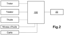
- Control means 100 of the pump 22 are described.
- the control means 100 are in particular adapted to control the stopping/starting of the pump, as a function of the received measurement of the oil temperature Tatti, as explained above.
- the control means 100 of the pump are also adapted to control the flow rate of the pump 22 as a function of the cooling requirement of the machine, defined as a function of the temperature of the active parts of the machine and taking into account the oil temperature.
- the temperature of the active parts of the machine is for example provided by an estimation of the temperature of the rotor Trotor and by a measurement of the temperature of the stator Tstator, acquired by a temperature sensor 33 installed at the stator.
- the control means may also be adapted to control the flow rate of the pump as a function of the oil level in the crankcase.
- the control means 100 are provided to ensure a minimum flow rate of the pump in order to empty the main oil reservoir to reach an oil level suitable for limiting oil-rotor contact.
- the control means can also be adapted to control the pump flow rate according to the machine's lubrication requirements, defined for example from a Carto map integrated into the control means, making it possible to guarantee a minimum flow rate delivered by the pump for lubrication purposes.
- the control means 100 can also be adapted so as to limit the speed of the pump, or even to stop it.
- different noise evaluation methods can be used, for example by analyzing the acoustic power produced.
- the operating conditions imply a need for lubrication or cooling of the machine, if the pump is stopped or has its speed limited, the machine normally risks reaching its thermal limits and/or the seals or bearings risk degradation.
Landscapes
- Engineering & Computer Science (AREA)
- Power Engineering (AREA)
- Microelectronics & Electronic Packaging (AREA)
- Chemical & Material Sciences (AREA)
- Combustion & Propulsion (AREA)
- Transportation (AREA)
- Mechanical Engineering (AREA)
- Motor Or Generator Cooling System (AREA)
Claims (10)
- Kühlsystem für eine elektrische Maschine (10), umfassend einen Rotor (13), umfassend eine rotierende Welle (15) und einen Stator (12), der an einer Innenwand eines Gehäuses (11) der Maschine befestigt ist und den Rotor umgibt, wobei das Gehäuse (11) mindestens eine Wellenlageraufnahme (17) aufweist, die ein Ende der Drehwelle über ein Lager (16) aufnimmt, das System umfassend:- einen Kreislauf (20), der eine Kühlflüssigkeit mit aktiven Teilen der elektrischen Maschine in Kontakt bringen kann,- einen Hauptbehälter (21), der sich in dem unteren Teil des Gehäuses befindet und die Kühlflüssigkeit aufnehmen kann,- eine Pumpe (22), die mit dem Hauptbehälter verbunden ist und die Kühlflüssigkeit in den Kreislauf einspritzen kann,wobei das System dadurch gekennzeichnet ist, dass das Flüssigkeitsvolumen des Hauptbehälters im Stillstand einen Kühlflüssigkeitsstand (30) in dem Gehäuse erreicht, das an einen unteren Teil des Rotors angrenzt, wobei der Kreislauf zu einem Nebenbehälter (27) führt, der sich in dem oberen Teil des Gehäuses befindet, wobei das System Mittel (100) zur Steuerung der Pumpe in Abhängigkeit von mindestens der Temperatur der Kühlflüssigkeit (TÖl) umfasst, wobei die Mittel zur Steuerung so angepasst sind, dass sie einerseits die Pumpe (22) im Stillstand halten, wenn die Temperatur der Kühlflüssigkeit unter einen vorgegebenen Schwellenwert fällt, sodass die Kühlflüssigkeit durch Einspritzen des Rotors in das Gehäuse gespritzt und in einem Behälter (32) gesammelt wird, der an der Oberfläche des Gehäuses auf der Seite des Lagergehäuses angebracht ist, das die Flüssigkeit zu dem Gleitlagergehäuse leiten kann, um das Lager zu schmieren und zu kühlen, und zum anderen das Anlaufen der Pumpe (22) zu steuern, sobald die Temperatur der Kühlflüssigkeit den Schwellenwert erreicht, so dass die Flüssigkeit von der Pumpe aus dem Hauptbehälter in den Kreislauf und zu dem Nebenbehälter gesaugt wird, wodurch der Kühlflüssigkeitsstand in dem Gehäuse gesenkt wird.
- Kühlsystem nach Anspruch 1, dadurch gekennzeichnet, dass der Nebenbehälter (27) mindestens einen an dem Umfang des Stators angeordneten Auslass (28, 29) mit einer Durchflussmenge umfasst, die so eingestellt werden kann, dass ein Teil der Längsaußenoberfläche des Stators mit Kühlflüssigkeit besprüht wird.
- System nach Anspruch 2, dadurch gekennzeichnet, dass der Nebenbehälter zwei einander gegenüberliegende Auslässe oder einen Auslass umfasst, der einen mittleren Umfangsabschnitt des Stators besprüht.
- System nach einem der Ansprüche 1 bis 3, dadurch gekennzeichnet, dass der Kreislauf (20) Durchflussdrosseln mit einstellbarer Durchflussmenge umfasst, die in dem Gehäuse so angeordnet sind, dass sie die Spulenköpfe des Rotors und die Wellenlageraufnahme besprühen.
- System nach einem der vorhergehenden Ansprüche, dadurch gekennzeichnet, dass die Mittel zur Steuerung (100) dazu angepasst sind, den Durchfluss der Pumpe (22) in Abhängigkeit von dem Ölstand (30) in dem Gehäuse zu steuern.
- System nach einem der vorhergehenden Ansprüche, dadurch gekennzeichnet, dass die Mittel zur Steuerung (100) dazu angepasst sind, den Durchfluss der Pumpe (22) in Abhängigkeit von der Temperatur (TStator, TRotor) der aktiven Teile der Maschine zu steuern.
- System nach einem der vorhergehenden Ansprüche, dadurch gekennzeichnet, dass die Mittel zur Steuerung (100) dazu angepasst sind, den Durchfluss der Pumpe (22) in Abhängigkeit von dem Schmierbedarf der Maschine zu steuern.
- System nach einem der vorhergehenden Ansprüche, dadurch gekennzeichnet, dass die Mittel zur Steuerung (100) dazu angepasst sind, die Drehzahl der Pumpe zumindest zu begrenzen oder sogar anzuhalten, wenn das von der Pumpe abgegebene Geräusch das von der elektrischen Maschine abgegebene Geräusch übersteigt.
- System nach einem der vorhergehenden Ansprüche, dadurch gekennzeichnet, dass das Gefäß (32) so ausgelegt ist, dass es an einen oberen Winkelabschnitt der Wellenlageraufnahme (17), auf der es angeordnet ist, angepasst ist und dass es über einen Kanal, der diesen oberen Winkelabschnitt der Wellenlageraufnahme durchquert, mit einem Raum zwischen dem Lager (16) und einer dynamischen Dichtung (18) kommuniziert, die die Gehäusewand verlängert, um die Maschine an dem Ausgang der Drehwelle (15) abzudichten.
- Elektro- oder Hybridkraftfahrzeug, aufweisend eine elektrische Antriebsmaschine und ein Kühlsystem für diese Maschine nach einem der vorhergehenden Ansprüche.
Applications Claiming Priority (2)
| Application Number | Priority Date | Filing Date | Title |
|---|---|---|---|
| FR2003828A FR3109483B1 (fr) | 2020-04-16 | 2020-04-16 | Système de refroidissement à huile d’une machine électrique |
| PCT/EP2021/058951 WO2021209285A1 (fr) | 2020-04-16 | 2021-04-06 | Système de refroidissement à huile d'une machine électrique |
Publications (2)
| Publication Number | Publication Date |
|---|---|
| EP4136740A1 EP4136740A1 (de) | 2023-02-22 |
| EP4136740B1 true EP4136740B1 (de) | 2025-06-25 |
Family
ID=70978253
Family Applications (1)
| Application Number | Title | Priority Date | Filing Date |
|---|---|---|---|
| EP21717055.4A Active EP4136740B1 (de) | 2020-04-16 | 2021-04-06 | Ölkühlsystem für einen elektromotor |
Country Status (7)
| Country | Link |
|---|---|
| US (1) | US12294242B2 (de) |
| EP (1) | EP4136740B1 (de) |
| JP (1) | JP2023522858A (de) |
| KR (1) | KR20230004676A (de) |
| CN (1) | CN115398784A (de) |
| FR (1) | FR3109483B1 (de) |
| WO (1) | WO2021209285A1 (de) |
Families Citing this family (8)
| Publication number | Priority date | Publication date | Assignee | Title |
|---|---|---|---|---|
| CN114301236A (zh) * | 2021-12-30 | 2022-04-08 | 中克骆瑞新能源科技有限公司 | 一种具有冷却三相引线的油冷扁线电机 |
| CN114337114A (zh) * | 2021-12-30 | 2022-04-12 | 中克骆瑞新能源科技有限公司 | 一种具有油液驱动喷淋结构的油冷扁线电机 |
| CN118659586A (zh) * | 2022-02-11 | 2024-09-17 | 华为数字能源技术有限公司 | 动力总成以及车辆 |
| JP2024157167A (ja) * | 2023-04-25 | 2024-11-07 | 本田技研工業株式会社 | 電動機の冷却装置 |
| JP2025001325A (ja) * | 2023-06-20 | 2025-01-08 | 株式会社日立製作所 | 回転電機および回転電機を用いた空気圧縮機 |
| CN221487520U (zh) * | 2023-10-31 | 2024-08-06 | 比亚迪股份有限公司 | 电机、电动总成和车辆 |
| TWI873956B (zh) * | 2023-11-01 | 2025-02-21 | 士林電機廠股份有限公司 | 馬達之冷卻結構 |
| CN117879264B (zh) * | 2024-03-12 | 2024-05-17 | 雅柯斯电力科技(中国)有限公司 | 一种发电机组、持续性照明系统及其工作方法 |
Citations (1)
| Publication number | Priority date | Publication date | Assignee | Title |
|---|---|---|---|---|
| EP2213497B1 (de) * | 2009-01-28 | 2011-09-28 | Hitachi Construction Machinery Co., Ltd. | Fahrantriebsvorrichtung für ein Nutzfahrzeug |
Family Cites Families (11)
| Publication number | Priority date | Publication date | Assignee | Title |
|---|---|---|---|---|
| US2736825A (en) * | 1951-06-12 | 1956-02-28 | Perfect Circle Corp | Electric motor |
| DE19824202C1 (de) * | 1998-05-29 | 1999-09-30 | Siemens Ag | Flüssigkeitsgekühlte elektrische Innenläufermaschine |
| FR2871107B1 (fr) * | 2004-06-03 | 2007-11-30 | Peugeot Citroen Automobiles Sa | Element fonctionnel de vehicule automobile comprenant un tel element de transmission a embrayages humides et un systeme hydraulique, et vehicule automobile equipe d'un tel ensemble fonctionnel |
| JP4586542B2 (ja) * | 2005-01-17 | 2010-11-24 | トヨタ自動車株式会社 | 回転電機 |
| US8169110B2 (en) * | 2009-10-09 | 2012-05-01 | GM Global Technology Operations LLC | Oil cooled motor/generator for an automotive powertrain |
| JP5706793B2 (ja) * | 2011-09-20 | 2015-04-22 | 日立建機株式会社 | 発電電動機とこれを用いた電動車両 |
| JP5772754B2 (ja) * | 2012-07-31 | 2015-09-02 | トヨタ自動車株式会社 | 電動車両の駆動装置 |
| JP2016201959A (ja) * | 2015-04-14 | 2016-12-01 | 三菱自動車工業株式会社 | 車両用電動モータの冷却装置 |
| SE539839C2 (sv) * | 2016-02-19 | 2017-12-19 | Scania Cv Ab | An arrangement for cooling of an electrical machine |
| JPWO2018030342A1 (ja) * | 2016-08-09 | 2019-06-13 | 日本電産株式会社 | モータユニット |
| FR3066334B1 (fr) | 2017-05-10 | 2019-05-03 | Renault Sas | Systeme de refroidissement a huile d'une machine electrique |
-
2020
- 2020-04-16 FR FR2003828A patent/FR3109483B1/fr active Active
-
2021
- 2021-04-06 KR KR1020227040178A patent/KR20230004676A/ko active Pending
- 2021-04-06 WO PCT/EP2021/058951 patent/WO2021209285A1/fr not_active Ceased
- 2021-04-06 CN CN202180028523.5A patent/CN115398784A/zh active Pending
- 2021-04-06 JP JP2022562036A patent/JP2023522858A/ja active Pending
- 2021-04-06 EP EP21717055.4A patent/EP4136740B1/de active Active
-
2022
- 2022-09-21 US US17/933,880 patent/US12294242B2/en active Active
Patent Citations (1)
| Publication number | Priority date | Publication date | Assignee | Title |
|---|---|---|---|---|
| EP2213497B1 (de) * | 2009-01-28 | 2011-09-28 | Hitachi Construction Machinery Co., Ltd. | Fahrantriebsvorrichtung für ein Nutzfahrzeug |
Also Published As
| Publication number | Publication date |
|---|---|
| JP2023522858A (ja) | 2023-06-01 |
| WO2021209285A1 (fr) | 2021-10-21 |
| FR3109483A1 (fr) | 2021-10-22 |
| FR3109483B1 (fr) | 2022-05-13 |
| KR20230004676A (ko) | 2023-01-06 |
| CN115398784A (zh) | 2022-11-25 |
| US20230036400A1 (en) | 2023-02-02 |
| US12294242B2 (en) | 2025-05-06 |
| EP4136740A1 (de) | 2023-02-22 |
Similar Documents
| Publication | Publication Date | Title |
|---|---|---|
| EP4136740B1 (de) | Ölkühlsystem für einen elektromotor | |
| EP3363103B1 (de) | Vorrichtung zur wärmeverwaltung eines elektrischen antriebsstrangs | |
| EP3953199B1 (de) | Kühlungs- und schmierungseinrichtung einer elektrischen antriebsbaugruppe eines elektro- oder hybrid-fahrzeugs | |
| EP3649725B1 (de) | Elektrische maschine mit einem system zur ölkühlung besagter elektrischer maschine | |
| EP1197644B1 (de) | System und Verfahren zur Kühlung eines Hybridfahrzeugs | |
| FR3030383A1 (fr) | Dispositif de gestion thermique d'un ensemble de motorisation electrique d'un vehicule automobile. | |
| CN209462156U (zh) | 旋转电机的冷却系统 | |
| EP4186149B1 (de) | Elektromotor und antriebssystem zur wärmeübertragung | |
| EP2900512B1 (de) | Fahrzeug mit verbesserter hydraulischer unterstützung mit einem system zur überwachung des ölstandes im gehäuse der hydraulischen vorrichtungen | |
| WO2014068471A1 (fr) | Procede de vidage d'un puits de petrole et systeme pour sa mise en œuvre | |
| WO2023110383A1 (fr) | Carter pour machine électrique, machine électrique, circuit de refroidissement, véhicule et procédé de refroidissement associés | |
| FR3028689A3 (fr) | Moteur electrique comprenant un circuit de refroidissement du rotor. | |
| WO2021052676A1 (fr) | Machine électrique refroidie à l'huile | |
| FR3052306A1 (fr) | Machine electrique tournante refroidie par un liquide de refroidissement | |
| EP4127417B1 (de) | Fluggasturbinenaufbau welcher ein verbessertes schmiersystem eines ein gebläse antreibendes untersetzungsgetriebes umfasst | |
| FR2882202A1 (fr) | Dispositif pour refroidir une machine tournante electrique et machine comportant un tel dispositif | |
| FR3105647A1 (fr) | Dispositif de transformation d'energie | |
| WO2016005890A1 (fr) | Plaque d'un compresseur électrique et compresseur électrique comprenant une telle plaque | |
| FR3152680A1 (fr) | Système de refroidissement pour moteur électrique. | |
| FR3071113A1 (fr) | Systeme de refroidissement pour machine electrique refroidie a l huile | |
| FR3156613A1 (fr) | Groupe moteur et engin de mobilité comportant un tel groupe moteur | |
| FR3118547A1 (fr) | Moteur électrique et véhicule comportant un tel moteur | |
| BE412354A (de) |
Legal Events
| Date | Code | Title | Description |
|---|---|---|---|
| STAA | Information on the status of an ep patent application or granted ep patent |
Free format text: STATUS: UNKNOWN |
|
| STAA | Information on the status of an ep patent application or granted ep patent |
Free format text: STATUS: THE INTERNATIONAL PUBLICATION HAS BEEN MADE |
|
| PUAI | Public reference made under article 153(3) epc to a published international application that has entered the european phase |
Free format text: ORIGINAL CODE: 0009012 |
|
| STAA | Information on the status of an ep patent application or granted ep patent |
Free format text: STATUS: REQUEST FOR EXAMINATION WAS MADE |
|
| 17P | Request for examination filed |
Effective date: 20220927 |
|
| AK | Designated contracting states |
Kind code of ref document: A1 Designated state(s): AL AT BE BG CH CY CZ DE DK EE ES FI FR GB GR HR HU IE IS IT LI LT LU LV MC MK MT NL NO PL PT RO RS SE SI SK SM TR |
|
| DAV | Request for validation of the european patent (deleted) | ||
| DAX | Request for extension of the european patent (deleted) | ||
| RAP1 | Party data changed (applicant data changed or rights of an application transferred) |
Owner name: NISSAN MOTOR CO., LTD. Owner name: AMPERE SAS |
|
| GRAP | Despatch of communication of intention to grant a patent |
Free format text: ORIGINAL CODE: EPIDOSNIGR1 |
|
| STAA | Information on the status of an ep patent application or granted ep patent |
Free format text: STATUS: GRANT OF PATENT IS INTENDED |
|
| INTG | Intention to grant announced |
Effective date: 20250115 |
|
| GRAS | Grant fee paid |
Free format text: ORIGINAL CODE: EPIDOSNIGR3 |
|
| GRAA | (expected) grant |
Free format text: ORIGINAL CODE: 0009210 |
|
| STAA | Information on the status of an ep patent application or granted ep patent |
Free format text: STATUS: THE PATENT HAS BEEN GRANTED |
|
| AK | Designated contracting states |
Kind code of ref document: B1 Designated state(s): AL AT BE BG CH CY CZ DE DK EE ES FI FR GB GR HR HU IE IS IT LI LT LU LV MC MK MT NL NO PL PT RO RS SE SI SK SM TR |
|
| REG | Reference to a national code |
Ref country code: GB Ref legal event code: FG4D Free format text: NOT ENGLISH |
|
| REG | Reference to a national code |
Ref country code: CH Ref legal event code: EP |
|
| REG | Reference to a national code |
Ref country code: CH Ref legal event code: EP |
|
| REG | Reference to a national code |
Ref country code: IE Ref legal event code: FG4D Free format text: LANGUAGE OF EP DOCUMENT: FRENCH |
|
| REG | Reference to a national code |
Ref country code: DE Ref legal event code: R096 Ref document number: 602021032822 Country of ref document: DE |
|
| PG25 | Lapsed in a contracting state [announced via postgrant information from national office to epo] |
Ref country code: FI Free format text: LAPSE BECAUSE OF FAILURE TO SUBMIT A TRANSLATION OF THE DESCRIPTION OR TO PAY THE FEE WITHIN THE PRESCRIBED TIME-LIMIT Effective date: 20250625 |
|
| REG | Reference to a national code |
Ref country code: LT Ref legal event code: MG9D |
|
| PG25 | Lapsed in a contracting state [announced via postgrant information from national office to epo] |
Ref country code: NO Free format text: LAPSE BECAUSE OF FAILURE TO SUBMIT A TRANSLATION OF THE DESCRIPTION OR TO PAY THE FEE WITHIN THE PRESCRIBED TIME-LIMIT Effective date: 20250925 Ref country code: GR Free format text: LAPSE BECAUSE OF FAILURE TO SUBMIT A TRANSLATION OF THE DESCRIPTION OR TO PAY THE FEE WITHIN THE PRESCRIBED TIME-LIMIT Effective date: 20250926 |
|
| PG25 | Lapsed in a contracting state [announced via postgrant information from national office to epo] |
Ref country code: BG Free format text: LAPSE BECAUSE OF FAILURE TO SUBMIT A TRANSLATION OF THE DESCRIPTION OR TO PAY THE FEE WITHIN THE PRESCRIBED TIME-LIMIT Effective date: 20250625 |
|
| PG25 | Lapsed in a contracting state [announced via postgrant information from national office to epo] |
Ref country code: HR Free format text: LAPSE BECAUSE OF FAILURE TO SUBMIT A TRANSLATION OF THE DESCRIPTION OR TO PAY THE FEE WITHIN THE PRESCRIBED TIME-LIMIT Effective date: 20250625 |
|
| PG25 | Lapsed in a contracting state [announced via postgrant information from national office to epo] |
Ref country code: RS Free format text: LAPSE BECAUSE OF FAILURE TO SUBMIT A TRANSLATION OF THE DESCRIPTION OR TO PAY THE FEE WITHIN THE PRESCRIBED TIME-LIMIT Effective date: 20250925 |
|
| PG25 | Lapsed in a contracting state [announced via postgrant information from national office to epo] |
Ref country code: LV Free format text: LAPSE BECAUSE OF FAILURE TO SUBMIT A TRANSLATION OF THE DESCRIPTION OR TO PAY THE FEE WITHIN THE PRESCRIBED TIME-LIMIT Effective date: 20250625 |
|
| REG | Reference to a national code |
Ref country code: NL Ref legal event code: MP Effective date: 20250625 |
|
| PG25 | Lapsed in a contracting state [announced via postgrant information from national office to epo] |
Ref country code: NL Free format text: LAPSE BECAUSE OF FAILURE TO SUBMIT A TRANSLATION OF THE DESCRIPTION OR TO PAY THE FEE WITHIN THE PRESCRIBED TIME-LIMIT Effective date: 20250625 |