EP4136474B1 - Sicherheitskörperscanner mit strahlungsenergie und zugehöriges detektionsverfahren - Google Patents
Sicherheitskörperscanner mit strahlungsenergie und zugehöriges detektionsverfahren Download PDFInfo
- Publication number
- EP4136474B1 EP4136474B1 EP21717128.9A EP21717128A EP4136474B1 EP 4136474 B1 EP4136474 B1 EP 4136474B1 EP 21717128 A EP21717128 A EP 21717128A EP 4136474 B1 EP4136474 B1 EP 4136474B1
- Authority
- EP
- European Patent Office
- Prior art keywords
- person
- inspected
- detector
- signals
- side panels
- Prior art date
- Legal status (The legal status is an assumption and is not a legal conclusion. Google has not performed a legal analysis and makes no representation as to the accuracy of the status listed.)
- Active
Links
Images


Classifications
-
- G—PHYSICS
- G01—MEASURING; TESTING
- G01S—RADIO DIRECTION-FINDING; RADIO NAVIGATION; DETERMINING DISTANCE OR VELOCITY BY USE OF RADIO WAVES; LOCATING OR PRESENCE-DETECTING BY USE OF THE REFLECTION OR RERADIATION OF RADIO WAVES; ANALOGOUS ARRANGEMENTS USING OTHER WAVES
- G01S13/00—Systems using the reflection or reradiation of radio waves, e.g. radar systems; Analogous systems using reflection or reradiation of waves whose nature or wavelength is irrelevant or unspecified
- G01S13/88—Radar or analogous systems specially adapted for specific applications
- G01S13/887—Radar or analogous systems specially adapted for specific applications for detection of concealed objects, e.g. contraband or weapons
-
- G—PHYSICS
- G01—MEASURING; TESTING
- G01S—RADIO DIRECTION-FINDING; RADIO NAVIGATION; DETERMINING DISTANCE OR VELOCITY BY USE OF RADIO WAVES; LOCATING OR PRESENCE-DETECTING BY USE OF THE REFLECTION OR RERADIATION OF RADIO WAVES; ANALOGOUS ARRANGEMENTS USING OTHER WAVES
- G01S13/00—Systems using the reflection or reradiation of radio waves, e.g. radar systems; Analogous systems using reflection or reradiation of waves whose nature or wavelength is irrelevant or unspecified
- G01S13/88—Radar or analogous systems specially adapted for specific applications
- G01S13/89—Radar or analogous systems specially adapted for specific applications for mapping or imaging
-
- G—PHYSICS
- G01—MEASURING; TESTING
- G01V—GEOPHYSICS; GRAVITATIONAL MEASUREMENTS; DETECTING MASSES OR OBJECTS; TAGS
- G01V3/00—Electric or magnetic prospecting or detecting; Measuring magnetic field characteristics of the earth, e.g. declination, deviation
- G01V3/08—Electric or magnetic prospecting or detecting; Measuring magnetic field characteristics of the earth, e.g. declination, deviation operating with magnetic or electric fields produced or modified by objects or geological structures or by detecting devices
-
- G—PHYSICS
- G01—MEASURING; TESTING
- G01V—GEOPHYSICS; GRAVITATIONAL MEASUREMENTS; DETECTING MASSES OR OBJECTS; TAGS
- G01V3/00—Electric or magnetic prospecting or detecting; Measuring magnetic field characteristics of the earth, e.g. declination, deviation
- G01V3/12—Electric or magnetic prospecting or detecting; Measuring magnetic field characteristics of the earth, e.g. declination, deviation operating with electromagnetic waves
-
- H—ELECTRICITY
- H04—ELECTRIC COMMUNICATION TECHNIQUE
- H04R—LOUDSPEAKERS, MICROPHONES, GRAMOPHONE PICK-UPS OR LIKE ACOUSTIC ELECTROMECHANICAL TRANSDUCERS; ELECTRIC HEARING AIDS; PUBLIC ADDRESS SYSTEMS
- H04R1/00—Details of transducers, loudspeakers or microphones
- H04R1/02—Casings; Cabinets ; Supports therefor; Mountings therein
- H04R1/025—Arrangements for fixing loudspeaker transducers, e.g. in a box, furniture
Definitions
- the present invention relates to the field of detectors designed for the detection of unauthorized objects or materials in a protected access area.
- the present invention relates in particular to the field of body scanners designed to inspect individuals, for example passengers before boarding, in airports, or individuals accessing a public site, for example a sports venue such as a stadium or a concert hall, in order to detect prohibited targets hidden under clothing.
- a sports venue such as a stadium or a concert hall
- Such devices make it possible in particular to avoid systematic pat-downs.
- continuous wave metal object detection portals have been proposed for many years, i.e. portals using waves of constant amplitude and frequency in frequency ranges between 70 Hz and 50 kHz typically. They comprise at least one transmitter winding and at least one receiver winding.
- the transmitter winding is powered by an alternating electric current.
- the receiver winding is designed to detect disturbances in the magnetic field generated by the transmitter winding due to the presence of a metal object, for example the attenuation of the amplitude of the magnetic field, or even the phase change of the signal, due for example to eddy currents generated on the metal object.
- body scanners have also been proposed.
- the oldest body scanners are X-ray body scanners.
- Newer body scanners use so-called millimeter wave (or microwave) technology.
- An example of a body scanner can be found in the document EP 2 202 700 .
- body scanners For several years, body scanners (generally referred to by their Anglo-Saxon terminology “body scanner”) have been developed in order to detect weapons, explosives, etc. hidden under the clothing of individuals entering a protected area. These scanners use technologies based on the detection of modulated radiation energies, reflected or emitted by the body of the individuals inspected.
- the radiation energies thus used include X-rays, microwaves, millimeter waves, infrared light, terahertz waves and ultrasound.
- these body scanners all operate on the principle of creating an electronic image of the individual on which the individual's clothing is transparent. This image is then displayed on a screen and viewed by an operator so that the operator can determine whether the individual is carrying a target object. To do this, the operator, who is trained in target object detection, must be able to determine whether the objects identified by the body scanner correspond to human anatomy, to an authorized object such as a lighter, a handkerchief or coins, or to a target object such as a weapon or explosive.
- the system may include software comprising code instructions to automatically analyze the image and determine the presence of any anomalies and display them on an avatar representing the person.
- the intensity of the energy reflected by these parts is very low and, due to their position relative to the transducers, a large part of the waves are reflected outside the plane in which the transmitting and receiving transducers are located. These reflected waves cannot therefore participate in the creation of the electronic image. This risk is all the greater as the surface area of the lateral part (i.e. the distance between its front face and its back face) of the person to be inspected is large.
- transducers specifically designed to scan these hidden areas in order to improve the radiation exposure of these areas.
- the increase in the number of transducers necessarily implies an increase in the processing time of the signals from these transducers to obtain a significant response from the lateral parts of the person to be inspected.
- This processing in terms of resources used and scanning time, is very inefficient compared to the imaging of the faces of the body that are parallel to the transducers (usually the front and back faces) which respond, on the contrary, with a much higher intensity and in the same direction of the transmitting and receiving transducers.
- a gantry comprising rotating mobile detection means mounted in a cylindrical wall.
- the rotation of the detection means thus makes it possible to scan circumferentially the person to be inspected so as to obtain a complete image of this person.
- it has a significant footprint on the ground, given its cylindrical shape, can be impressive for the persons inspected, and the time for scanning and processing the information thus collected can be long.
- the circumferential scanning of the person inspected cannot be complete since the system must provide two openings to allow the entry and exit of the person to be inspected.
- the total scanning angle is at most 240 degrees, so that the person is not inspected over 60 degrees in correspondence with the entry and over 60 degrees in correspondence with the exit.
- An aim of the invention is to propose a detection method and associated detector using radiant energy for the detection of target objects which overcomes the aforementioned drawbacks.
- an aim of the invention is to provide a detection method and an associated radiant energy detector capable of more reliably detecting target objects carried by a person, even when these targets are located in areas which are more difficult to explore by radiant energy, which makes it possible to reduce the number of resources necessary for implementing the method while remaining fast, efficient and with a reduced false alarm rate.
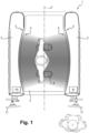
- a detector 1 of radiant energy target objects comprises two opposite side panels 2 which are fixed and together delimit a passage forming a transit channel for a person to be inspected.
- the side panels 2 are substantially symmetrical with respect to a central plane P (fictitious plane of symmetry).
- the side panels 2 are connected at their upper edge by a ceiling and/or at their lower edge by a platform 4 so as to be monobloc.
- the side panels 2 may be separate and distinct, i.e. not connected via a ceiling or a platform 4.
- Each side panel 2 has an internal face 3, oriented towards the passage. More precisely, the internal face 3 of the first side panel 2 faces the internal face 3 of the second side panel 2 so as to laterally delimit the passage.
- the detector 1 further comprises a series of radiant energy transmitter/receiver transducers 5 and a central unit 6 configured to receive signals representative of the radiant energy reflected and measured by the transducers 5 and to deduce an electronic image therefrom.
- the transducers 5 are arranged at the internal face 3 of at least one of the side panels 2, preferably of each side panel 2. Each transducer can successively form a transmitter configured to generate radiant energy and a receiver configured to receive radiant energy.
- each transducer includes an antenna 5 configured to generate radiant energy of the millimeter wave (also called microwave wave), X-ray, terahertz wave, etc. type.
- millimeter wave also called microwave wave
- X-ray X-ray
- terahertz wave terahertz wave
- the transducers 5 comprise microwave antennas 5, that is to say antennas 5 configured to generate waves whose length is between 3 mm and 20 mm inclusive (i.e. a frequency range from approximately 15 GHz to 100 GHz), without this being limiting.
- Microwave waves are in fact suitable for the detection of metallic and non-metallic objects, such as for example ceramic objects.
- air and other materials, such as those used for clothing are transparent to these radiations. It follows that microwave waves can be used for the detection of objects concealed under clothing.
- the microwave antennas 5, as transmitters generate pulses or a frequency sweep of microwave waves.
- the detector 1 further comprises a network interface configured to receive the signals representative of the reflected energy and transmit them to the central unit 6.
- the central unit 6 may in particular comprise a computer of the processor, microprocessor, microcontroller, etc. type, configured to execute code instructions in order to process the signals representative of the radiant energy reflected and measured by the transducers 5 and to deduce the electronic image therefrom.
- the detector 1 further comprises presence detection means, for example an optical barrier placed at the entrance to the detector 1.
- the detector 1 further comprises a signal, which can be placed at the entrance to the detector 1 and synchronized with the presence detection means, in order to indicate to the person being inspected whether they can enter the detector 1.
- the signal may for example be of the green light/red light type (see Fig. 5 ).
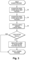
- step S1 the person being inspected is placed in the detector 1, between the side panels 2, in a first position.
- This first position may be conventional and correspond for example to a position in which the person to be inspected is placed facing one of the side panels 2, generally in the central plane P, with their legs spread apart substantially parallel to this central plane P. The person may leave their arms alongside their body or, as a variant, spread them apart, in the central plane P. This first position has been illustrated in figure 1 .
- the antennas 5 are therefore capable of generating microwave waves scanning the front face (respectively, the rear face) of the person being inspected, so that the first electronic image obtained represents the front face (respectively, the rear face) of the person to be inspected.
- step S2 all or part of the microwave antennas 5 housed in the first side panel 2 and/or the second side panel 2 generate and emit pulses or trains of microwave waves in the direction of the passage.
- These microwave waves interact with the facing surface, namely the body of the person to be inspected, their clothing and any object possibly concealed by this person under their clothing as well as the internal face 3 of the facing side panel 2. This interaction modulates the energy of the microwave waves which, once reflected, return to the antenna(s) 5, which act as a receiver.
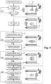
- each antenna 5 transmits to the central unit 6 a first signal representative of this reflected energy (steps 2.1 and S4.1) for the purpose of processing it and producing the electronic image of the person to be inspected (step S5). If necessary, this transmission can be carried out via a network interface.
- the person is placed in a second position, distinct from the first position.
- the person to be inspected pivots on himself between the first position and the second position, the objective being to position a different surface of the body facing the side panels 2.
- the pivot angle between the first position and the second position is therefore different from 180°, in particular when the two side panels 2 house microwave antennas 5 (the antennas 5 of one of the panels making it possible to generate an electronic image of the front face of the person and the antennas 5 of the other of the panels making it possible to generate an electronic image of the back face of the person).
- the person to be inspected makes a quarter turn to pass from the first position to the second position, so that the angle between the first position and the second position is equal to approximately 90° (to within 20 degrees) (modulo 180°).
- the second position is substantially perpendicular to the first position
- the lateral surfaces of the person to be inspected which were perpendicular to the internal faces 3 of the side panels 2 during the acquisition step S2, are facing the side panels 2 during the acquisition step S4.
- This therefore improves the capacity of the microwave antennas 5 to explore the lateral faces of the person to be inspected and increases the intensity of the energy reflected by these lateral faces in step S4, in comparison with the energy reflected by these same parts during step S2. It follows that the number of resources (5 microwave antennas) required to improve detection in these areas can be reduced, as can the processing time of the first and second signals.
- the person can raise his arms so as to place them in front of him or on the sides, at the height of his shoulders, substantially parallel to the ground.
- the antennas 5 are therefore capable of scanning the entire right lateral face (respectively, the left lateral face) of the person being inspected, so that the second electronic image obtained represents the right lateral face (respectively, the left lateral face) of the person to be inspected.
- Step S4 is generally identical to step S2, except for the position of the person to be inspected (placed in the second position rather than in the first position).
- each antenna 5 transmits to the central unit 6 a second signal representative of the energy reflected by the person inspected in the second position for the purpose of its processing by the central unit 6 and the production of the electronic image.
- this transmission may be carried out via a network interface.
- Step S4 may be initiated automatically by the central unit 6.
- the detector 1 may comprise detection means (photovoltaic barriers, presence detection, etc.) placed in the ground or in the side panels 2 configured to determine whether the person to be inspected is in the second position.
- step S4 may be initiated manually by a security agent, for example by pressing an acquisition button, when the person is correctly placed in the second position.
- the method further comprises a step S6 during which the central unit 6 sends instructions to one or more indicators 7 configured to guide the person being inspected and place them in the first position and/or in the second position. These indicators may for example be visual and/or audible.
- the central unit 6 thus makes it possible to coordinate the placement steps S1 and S3 with the acquisition steps S2 and S4.
- the indicator 7 comprises one or more lights placed in the platform 4 of the detector 1 and configured to receive switching on and off instructions from the central unit 6.
- the detector 1 may comprise a series of light-emitting diodes (LEDs) 7, positioned so as to form two sets of shoe prints, a first set 8 corresponding to the position of the feet of the person to be inspected in the first position (for example facing one of the side panels 2), in the central plane P, the second set 9 corresponding to the position of the feet of the person to be inspected in the second position (for example perpendicular to the side panels 2 and to the central plane P).
- LEDs light-emitting diodes
- the LEDs forming the first set 8 of prints are lit in order to guide the person to be inspected and to help him/her to position himself/herself correctly in the first position within the detector 1, with a view to acquiring the first electronic image during phase S2. Following step S2, these LEDs are extinguished.
- the LEDs forming the second set 9 of footprints are lit between the moment when the LEDs forming the first set 8 of footprints are switched off and the start of step S3. In this way, the person to be inspected is encouraged to pivot on himself to place his feet in the second set 9 of footprints and thus position himself in the second position.
- the LEDs forming the second set 9 of footprints are switched off before step S5, for example at the end of step S4.
- the first set 8 of prints and the second set 9 of prints can remain lit simultaneously throughout the detection process (as shown for example in the figure 5 ), the person to be inspected being invited to position his feet in one or the other game by oral instructions given by a security agent or broadcast by a loudspeaker.
- the indicator 7 of the detector 1 comprises a projector configured to project one or more images onto the inner face 3 of one of the side panels 2 and/or onto the platform 4.
- the image(s) projected onto the inner face 3 may in particular have the function of providing information regarding the sequence of positions as well as their sequence during the implementation of the detection method.
- the images projected onto the platform 4 may correspond to a first set 8 of prints and a second set 9 of prints, the successive steps of projection of which onto the platform 4 correspond to the steps of switching on and off the LEDs forming the first and second sets 9x of prints described in the first embodiment.
- the indicator 7 of the detector 1 is audible and comprises a loudspeaker 10, which can be fixed directly to the detector 1 or be placed at a distance from the latter.
- the loudspeaker 10 is then configured to emit an audible message to the person to be inspected. For example, when the person to be inspected enters the detector 1 and/or during step S1, the loudspeaker 10 emits an audible message to guide the person to be inspected and help them to position themselves correctly in the first position within the detector 1, with a view to acquiring the first electronic image during phase S2.
- the loudspeaker 10 emits an audible message following step S2 to invite the person to be inspected to pivot on themselves, for example by a quarter turn, and position themselves in the second position.
- the loudspeaker can emit an audio message to invite the person to exit the detector 1.
- the instructions are given orally to the person to be inspected by a security officer, who directly asks the person to be inspected to move from the first position to the second position.
- first, second and third embodiments of the indicator 7 are cumulative (combination of a loudspeaker 10 or oral instructions with lights 8, 9 and/or a projector).
- step S5 the central unit 6 processes the first signals and the second signals representative of the reflected radiant energy and produces one or more electronic images.
- the central unit 6 can produce one or more first electronic images and one or more second electronic images (when each side panel 2 comprises microwave antennas 5 alternately playing the role of transmitter and receiver). receiver) from the first and second signals generated by the antennas 5 of each side panel 2 in steps S1 and S3, respectively.
- the central unit 6 can be configured to produce a single electronic image from the first and second signals.
- This single electronic image can be of the “elliptical” or “developed” type and reproduce the surface of the person to be inspected over 360° (in particular when each side panel 2 comprises microwave antennas 5).
- the first signals are transmitted to the central unit 6.
- these first signals are transmitted by the microwave antennas 5 as soon as they are acquired.
- the central unit 6 processes the first signals as soon as they are received (step S2.2). More precisely, the central unit 6 processes the first signals before receiving the second signals (see Figure 4 ). Thus, the central unit 6 begins processing the first signals during the passage of the person to be inspected from the first position to the second position and, if applicable, during the acquisition of the second signals. In this way, when the central unit 6 receives the second signals, the first signals are already processed in whole or in part (depending on the duration of processing of the first signals and the duration of carrying out steps S3 and S4), which allows it to immediately start processing of the second signals. The results of the processing of the first and second signals are therefore faster.
- the transmission and processing (steps S2.1 and S2.2) of the first signals before and/or simultaneously with the transmission (step S4.1) of the second signals therefore reduces the total duration of the detection method S by two to six seconds. It follows that, by the time the person being inspected leaves the detector 1, the security officer already has the result of the processing of the signals by the central unit 6. It is therefore not necessary to make the person being inspected wait. In addition, the detector 1 becomes immediately available for the inspection of a new person to be inspected upon exit of the person who has just been inspected by detector 1.
- the detection method S of the invention is therefore more efficient, since it is capable of reliably inspecting all parts of the body of a person to be inspected, without requiring an increase in the sensitivity of the detector 1 or the duration of the detection method S.
- the detector 1 further comprises a screen 11 configured to display an electronic image generated by the central unit 6.
- the screen 11 may be mounted on the detector 1, for example on one of the side panels 2 at the output of the detector 1, or alternatively placed remotely and communicate via a wireless or wired interface with the central unit.
- a screen 11 may be mounted on each side panel 2.
- the internal face 3 of the panels can be curved, the center of the curvature being placed opposite the internal face 3. More precisely, in this embodiment, the curvature of the internal faces 3 of the side panels 2 is such that the distance between the internal faces 3 in a plane perpendicular to the central plane P increases progressively from the entrance of the detector 1 to a maximum distance, then decreases progressively towards the exit of the detector 1.
- the internal faces 3 can be planar in pieces, the sections together forming a channel diverging then converging, from the entrance to the exit.
- the internal faces 3 can for example each successively comprise at least one flat section inclined relative to the central plane P so that the passage diverges (relative to the direction of passage in the detector 1, i.e. from the entrance to the exit of the passage), then a flat section substantially parallel to the central plane P and at least one section inclined relative to the central plane P so that the passage converges towards the exit.
- the surface area of the inspected person that can be reached by microwave waves is larger when the inner face 3 of the side walls is curved (continuously or in pieces), which further increases the reliability of detection.
- the central unit 6 produces a single electronic image from the first signals and the second signals (step S5).
- the single electronic image therefore reproduces all of the information obtained by the central unit 6 from the first signals and the second signals.
- the single electronic image is a representation of the elements identified by the detector 1 over the entire circumference (360°) of the person being inspected and therefore includes the front face, the back face and the side faces of the person being inspected.
- the security officer therefore has, in a single image, all the information necessary to inspect the person.
- This unique electronic image can be of the elliptical type (in three dimensions) or developed (in two dimensions).
- the central unit 6 produces one or more first electronic images from the first signals (one per side panel 2 comprising microwave antennas 5) and one or more second electronic images from the second signals (one per side panel 2 comprising microwave antennas 5) (step S5).
- These electronic images can be displayed successively on the screen, or alternatively merged to obtain a single electronic image which will be displayed on the screen.
- the system may include software comprising code instructions to automatically analyze the image and determine the presence of any anomalies and display them on an avatar representing the person.
Landscapes
- Engineering & Computer Science (AREA)
- Remote Sensing (AREA)
- Physics & Mathematics (AREA)
- Radar, Positioning & Navigation (AREA)
- General Physics & Mathematics (AREA)
- Electromagnetism (AREA)
- Life Sciences & Earth Sciences (AREA)
- Computer Networks & Wireless Communication (AREA)
- General Life Sciences & Earth Sciences (AREA)
- Geophysics (AREA)
- Environmental & Geological Engineering (AREA)
- Geology (AREA)
- Acoustics & Sound (AREA)
- Signal Processing (AREA)
- Geophysics And Detection Of Objects (AREA)
- Radar Systems Or Details Thereof (AREA)
- Burglar Alarm Systems (AREA)
- Photometry And Measurement Of Optical Pulse Characteristics (AREA)
Claims (15)
- Verfahren zum Detektieren (S) eines Zielobjekts mithilfe eines Detektors (1) mit Strahlungsenergie, wobei der Detektor (1) zwei gegenüberliegende Seitenplatten (2) umfasst, wobei die Seitenplatten (2) feststehend sind und gemeinsam einen Durchgang begrenzen,wobei das Verfahren zum Detektieren (S) die folgenden Schritte umfasst:S1: Platzieren einer zu inspizierenden Person in eine erste Position innerhalb des Durchgangs zwischen den Seitenplatten (2) des Detektors (1);S2: Erfassen erster Signale, die repräsentativ für eine Strahlungsenergie sind, wenn die zu inspizierende Person in einer ersten Position ist;S3: Platzieren der zu inspizierenden Person in eine zweite Position innerhalb des Durchgangs zwischen den Seitenplatten (2) des Detektors (1), wobei sich die zweite Position von der ersten Position unterscheidet; undS4: Erfassen zweiter Signale, die repräsentativ für eine Strahlungsenergie sind, wenn die zu inspizierende Person in einer zweiten Position ist; undS5: Erstellen aus den ersten Signalen und den zweiten Signalen eines elektronischen Bildes, um zu bestimmen, ob die zu inspizierende Person ein Zielobjekt trägt;wobei im Laufe des einen aus den Schritten S1 und S3 die zu inspizierende Person gegenüber einer der Seitenplatten (2) platziert wird, und im Laufe des anderen aus den Schritten S1 und S3 die zu inspizierende Person senkrecht zu den Seitenplatten (2) platziert wird.
- Verfahren zum Detektieren (S) nach Anspruch 1, wobei die inspizierte Person zwischen der ersten Position und der zweiten Position in einem Winkel um sich selbst schwenkt, der sich von 180° unterscheidet.
- Verfahren zum Detektieren (S) nach einem der Ansprüche 1 und 2, das weiter vor dem Schritt S3 einen Schritt S6 zum Senden von Anweisungen an die inspizierte Person umfasst, um sie von der ersten Position in die zweite Position übergehen zu lassen.
- Verfahren zum Detektieren (S) nach Anspruch 3, wobei die Anweisungen im Laufe des Schrittes S6 visuell und/oder akustisch sind.
- Verfahren zum Detektieren (S) nach einem der Ansprüche 3 oder 4, wobei die Anweisungen über eine Zentrale (6) des Detektors (1) gesendet werden.
- Verfahren zum Detektieren (S) nach einem der Ansprüche 4 oder 5, wobei die Anweisungen durch eine Zentraleinheit (6) des Detektors (1) im Laufe des Schrittes S1 gesendet werden, wobei die zu inspizierende Person gegenüber einer der Seitenplatten (2) platziert wird, und die zu inspizierende Person im Laufe des Schrittes S3 senkrecht zu den Seitenplatten (2) platziert wird.
- Verfahren zum Detektieren (S) nach einem der Ansprüche 1 bis 6, wobei die inspizierte Person im Laufe des Schrittes S1 und/oder S3 ihre Arme im Abstand von ihrem Körper platziert.
- Verfahren zum Detektieren (S) nach einem der Ansprüche 1 bis 7, das weiter einen Schritt zum Verarbeiten (S2.2; S4.2; S5) der ersten Signale und der zweiten Signale durch eine Zentraleinheit (6) umfasst, um ein Zielobjekt zu detektieren, das von der zu inspizierenden Person getragen wird.
- Verfahren zum Detektieren (S) nach Anspruch 8, wobei die ersten Signale vor dem Schritt S4 an eine Zentraleinheit (6) übertragen (S2.1) werden.
- Verfahren zum Detektieren (S) nach Anspruch 9, wobei die ersten Signale während der gesamten oder einem Teil der Schritte S3 und S4 verarbeitet (S2.2) werden.
- Verfahren zum Detektieren (S) nach einem der Ansprüche 8 bis 10, wobei die Zentraleinheit (6) die ersten Signale und die zweiten Signale kombiniert, um ein eindeutiges elektronisches Bild der zu inspizierenden Person zu erzeugen.
- Detektor (1) mit Strahlungsenergie, umfassend:- zwei gegenüberliegende Seitenplatten (2), die in Bezug zueinander feststehend sind und gemeinsam einen Durchgang begrenzen;- Strahlungsenergiewandler (5), beispielsweise Mikrowellenantennen, die in mindestens einer der Seitenplatten (2) untergebracht sind; und- eine Zentraleinheit (6), die konfiguriert ist, um ein Verfahren zum Detektieren (S) nach einem der Ansprüche 1 bis 11 auszuführen.
- Detektor (1) nach Anspruch 12, der weiter eine optische und/oder akustische Anzeige (7) umfasst, wobei die Zentraleinheit (6) konfiguriert ist, um Anweisungen an die optische und/oder akustische Anzeige (7) zu senden, um eine zu inspizierende Person von der ersten Position in die zeite Position übergehen zu lassen.
- Detektor (1) nach Anspruch 13, wobei die optische Anzeige (7) mindestens eines der folgenden Mittel umfasst:- eine oder mehrere Leuchten (8, 9), die in einer Plattform (4) platziert ist/sind, die sich zwischen den Seitenplatten (2) erstreckt;- einen Projektor, der konfiguriert ist, um ein oder mehrere Bilder auf die Plattform (4) und/oder auf mindestens eine Seitenplatte (2) zu projizieren;- einen Lautsprecher (10), der konfiguriert ist, um eine Sprachnachricht an die zu inspizierende Person auszugeben.
- Detektor (1) nach einem der Ansprüche 12 bis 14, wobei die Seitenplatten (2) jeweils eine zur gegenüberliegenden Seitenplatte (2) ausgerichtete Innenseite (3) aufweisen, wobei die Innenseiten gekrümmt sind.
Applications Claiming Priority (2)
| Application Number | Priority Date | Filing Date | Title |
|---|---|---|---|
| FR2003724A FR3109223B1 (fr) | 2020-04-14 | 2020-04-14 | Scanner corporel de sécurité à énergie rayonnante et procédé de détection associé |
| PCT/EP2021/059675 WO2021209505A1 (fr) | 2020-04-14 | 2021-04-14 | Scanner corporel de sécurité à énergie rayonnante et procédé de détection associé |
Publications (2)
| Publication Number | Publication Date |
|---|---|
| EP4136474A1 EP4136474A1 (de) | 2023-02-22 |
| EP4136474B1 true EP4136474B1 (de) | 2024-10-30 |
Family
ID=72709417
Family Applications (1)
| Application Number | Title | Priority Date | Filing Date |
|---|---|---|---|
| EP21717128.9A Active EP4136474B1 (de) | 2020-04-14 | 2021-04-14 | Sicherheitskörperscanner mit strahlungsenergie und zugehöriges detektionsverfahren |
Country Status (12)
| Country | Link |
|---|---|
| US (1) | US20230131216A1 (de) |
| EP (1) | EP4136474B1 (de) |
| JP (2) | JP2023521811A (de) |
| KR (1) | KR20230002471A (de) |
| CN (1) | CN115398268A (de) |
| AU (1) | AU2021256736B2 (de) |
| CA (1) | CA3173071A1 (de) |
| DK (1) | DK4136474T3 (de) |
| ES (1) | ES3014166T3 (de) |
| FI (1) | FI4136474T3 (de) |
| FR (1) | FR3109223B1 (de) |
| WO (1) | WO2021209505A1 (de) |
Families Citing this family (4)
| Publication number | Priority date | Publication date | Assignee | Title |
|---|---|---|---|---|
| KR102165253B1 (ko) * | 2020-05-27 | 2020-10-13 | 인천국제공항공사 | 보안 검색중 수검 예외 처리를 위한 자동 출입 통제 시스템 및 방법 |
| CN114252931B (zh) * | 2020-09-21 | 2025-08-01 | 同方威视技术股份有限公司 | 基于双站姿的毫米波人体安检系统和方法 |
| NL2026564B1 (en) * | 2020-09-28 | 2022-05-30 | Scarabee Systems & Tech B V | screening device for screening a person |
| FR3162085A1 (fr) | 2024-05-10 | 2025-11-14 | Alessandro Manneschi | Prise en compte des chaussures dans la détection d’objets ou matières non autorisés dans une zone à accès protégé |
Family Cites Families (14)
| Publication number | Priority date | Publication date | Assignee | Title |
|---|---|---|---|---|
| US6094472A (en) * | 1998-04-14 | 2000-07-25 | Rapiscan Security Products, Inc. | X-ray backscatter imaging system including moving body tracking assembly |
| US7405692B2 (en) * | 2001-03-16 | 2008-07-29 | Battelle Memorial Institute | Detecting concealed objects at a checkpoint |
| US8350747B2 (en) * | 2004-04-14 | 2013-01-08 | L-3 Communications Security And Detection Systems, Inc. | Surveillance with subject screening |
| US8638904B2 (en) * | 2010-03-14 | 2014-01-28 | Rapiscan Systems, Inc. | Personnel screening system |
| JP2010008272A (ja) * | 2008-06-27 | 2010-01-14 | Maspro Denkoh Corp | ミリ波撮像装置 |
| EP2202700B1 (de) | 2008-12-24 | 2012-10-03 | Alessandro Manneschi | System zum Kontrollieren einer Person |
| US20130307714A1 (en) * | 2012-05-03 | 2013-11-21 | MVT Equity, LLC | Passive Millimeter Wave Imaging System with Environmental Control for Concealed Object Detection |
| CN104375143A (zh) * | 2013-08-15 | 2015-02-25 | 同方威视技术股份有限公司 | 毫米波三维全息扫描成像设备及人体或物品检查方法 |
| DE102014210227A1 (de) * | 2014-01-23 | 2015-07-23 | Rohde & Schwarz Gmbh & Co. Kg | System und Verfahren zur effizienten Abtastung von Gegenständen |
| JP6276736B2 (ja) * | 2015-08-20 | 2018-02-07 | 海洋総合開発株式会社 | 物質識別装置 |
| CN106896359A (zh) * | 2015-12-17 | 2017-06-27 | 上海铭剑电子科技有限公司 | 主动式毫米波三维全息成像系统及安检系统 |
| JP7003023B2 (ja) * | 2018-09-28 | 2022-02-10 | 株式会社熊平製作所 | 金属検出装置 |
| CN109471099A (zh) * | 2018-11-12 | 2019-03-15 | 山东雷诚电子科技有限公司 | 一种环境共形人体安检毫米波三维成像系统 |
| US11574515B2 (en) * | 2019-04-05 | 2023-02-07 | The Government of the United States of America, as represented by the Secretary of Homeland Security | Fully-automated self-divesting screening system and method |
-
2020
- 2020-04-14 FR FR2003724A patent/FR3109223B1/fr active Active
-
2021
- 2021-04-14 ES ES21717128T patent/ES3014166T3/es active Active
- 2021-04-14 JP JP2022562249A patent/JP2023521811A/ja active Pending
- 2021-04-14 DK DK21717128.9T patent/DK4136474T3/da active
- 2021-04-14 US US17/918,775 patent/US20230131216A1/en active Pending
- 2021-04-14 WO PCT/EP2021/059675 patent/WO2021209505A1/fr not_active Ceased
- 2021-04-14 EP EP21717128.9A patent/EP4136474B1/de active Active
- 2021-04-14 FI FIEP21717128.9T patent/FI4136474T3/fi active
- 2021-04-14 KR KR1020227036816A patent/KR20230002471A/ko not_active Ceased
- 2021-04-14 CA CA3173071A patent/CA3173071A1/fr active Pending
- 2021-04-14 CN CN202180028697.1A patent/CN115398268A/zh active Pending
- 2021-04-14 AU AU2021256736A patent/AU2021256736B2/en active Active
-
2025
- 2025-11-04 JP JP2025185344A patent/JP2026012392A/ja active Pending
Also Published As
| Publication number | Publication date |
|---|---|
| CA3173071A1 (fr) | 2021-10-21 |
| JP2026012392A (ja) | 2026-01-23 |
| ES3014166T3 (en) | 2025-04-21 |
| DK4136474T3 (da) | 2025-01-27 |
| EP4136474A1 (de) | 2023-02-22 |
| WO2021209505A1 (fr) | 2021-10-21 |
| KR20230002471A (ko) | 2023-01-05 |
| US20230131216A1 (en) | 2023-04-27 |
| JP2023521811A (ja) | 2023-05-25 |
| AU2021256736B2 (en) | 2026-04-09 |
| FR3109223B1 (fr) | 2022-04-08 |
| CN115398268A (zh) | 2022-11-25 |
| FR3109223A1 (fr) | 2021-10-15 |
| FI4136474T3 (fi) | 2025-02-04 |
| AU2021256736A1 (en) | 2022-10-06 |
Similar Documents
| Publication | Publication Date | Title |
|---|---|---|
| EP4136474B1 (de) | Sicherheitskörperscanner mit strahlungsenergie und zugehöriges detektionsverfahren | |
| EP3918377B1 (de) | Verbesserte metalldetektoreinrichtungen zur ortung der präsenz von metallischen objekten | |
| EP3721267B1 (de) | Doppelfeld-detektionssystem und detektionsverfahren | |
| EP3470890B1 (de) | Vorrichtung und verfahren zur detektion von nicht erlaubten gegenständen oder substanzen, die von einer person in eine zone mit geschütztem zugang gebracht werden | |
| US8159534B2 (en) | Method for remote inspection of target in monitored space | |
| CA2589923C (fr) | Portique detecteur de metaux comportant des moyens indicateurs perfectionnes | |
| EP3470891B1 (de) | Inspektion eines schuhs mit einer wärmebildkamera | |
| CA3050509A1 (fr) | Detecteur d'objets ou de matieres non autorisees dissimules dans une chaussure | |
| EP0764316A1 (de) | Überwachungs- und warnungsvorrichtung zur vermutung von körpern in gefahr in einem schwimmbecken | |
| FR2959020A1 (fr) | Dispositif de detection instantanee d'objets caches par imagerie a 360 degres | |
| WO2021099217A1 (fr) | Détecteur intégré à faible encombrement | |
| RU2834308C1 (ru) | Способ обнаружения целевого объекта с использованием детектора, использующего энергию излучения, и соответствующий детектор | |
| EP3470887B1 (de) | Vorrichtung und verfahren zur inspektion des beines einer person zum feststellen des tragens von unzulässigen gegenständen | |
| EP2047330B1 (de) | Einrichtung zum erfassen der silhouette einer person | |
| CH718437A2 (fr) | Procédé et système de contrôle de visiteurs dans une zone d'accès à l'intérieur d'un parc de loisir. | |
| FR3162085A1 (fr) | Prise en compte des chaussures dans la détection d’objets ou matières non autorisés dans une zone à accès protégé | |
| WO2013107969A1 (fr) | Appareil de detection par onde electromagnetique de mouvement d'un corps masque | |
| EP3918379A1 (de) | Gepäckdetektor | |
| FR3019426A1 (fr) | Dispositif d'imagerie et procede d'imagerie correspondant |
Legal Events
| Date | Code | Title | Description |
|---|---|---|---|
| STAA | Information on the status of an ep patent application or granted ep patent |
Free format text: STATUS: UNKNOWN |
|
| STAA | Information on the status of an ep patent application or granted ep patent |
Free format text: STATUS: THE INTERNATIONAL PUBLICATION HAS BEEN MADE |
|
| PUAI | Public reference made under article 153(3) epc to a published international application that has entered the european phase |
Free format text: ORIGINAL CODE: 0009012 |
|
| STAA | Information on the status of an ep patent application or granted ep patent |
Free format text: STATUS: REQUEST FOR EXAMINATION WAS MADE |
|
| 17P | Request for examination filed |
Effective date: 20221109 |
|
| AK | Designated contracting states |
Kind code of ref document: A1 Designated state(s): AL AT BE BG CH CY CZ DE DK EE ES FI FR GB GR HR HU IE IS IT LI LT LU LV MC MK MT NL NO PL PT RO RS SE SI SK SM TR |
|
| DAV | Request for validation of the european patent (deleted) | ||
| DAX | Request for extension of the european patent (deleted) | ||
| REG | Reference to a national code |
Ref country code: DE Ref legal event code: R079 Free format text: PREVIOUS MAIN CLASS: G01S0013880000 Ref country code: DE Ref legal event code: R079 Ref document number: 602021021001 Country of ref document: DE Free format text: PREVIOUS MAIN CLASS: G01S0013880000 Ipc: G01S0013890000 |
|
| GRAP | Despatch of communication of intention to grant a patent |
Free format text: ORIGINAL CODE: EPIDOSNIGR1 |
|
| STAA | Information on the status of an ep patent application or granted ep patent |
Free format text: STATUS: GRANT OF PATENT IS INTENDED |
|
| RIC1 | Information provided on ipc code assigned before grant |
Ipc: G01V 3/12 20060101ALI20240718BHEP Ipc: G01S 13/88 20060101ALI20240718BHEP Ipc: G01V 3/10 20060101ALI20240718BHEP Ipc: G01V 3/08 20060101ALI20240718BHEP Ipc: G01S 13/89 20060101AFI20240718BHEP |
|
| INTG | Intention to grant announced |
Effective date: 20240802 |
|
| GRAS | Grant fee paid |
Free format text: ORIGINAL CODE: EPIDOSNIGR3 |
|
| GRAA | (expected) grant |
Free format text: ORIGINAL CODE: 0009210 |
|
| STAA | Information on the status of an ep patent application or granted ep patent |
Free format text: STATUS: THE PATENT HAS BEEN GRANTED |
|
| P01 | Opt-out of the competence of the unified patent court (upc) registered |
Free format text: CASE NUMBER: APP_52416/2024 Effective date: 20240918 |
|
| AK | Designated contracting states |
Kind code of ref document: B1 Designated state(s): AL AT BE BG CH CY CZ DE DK EE ES FI FR GB GR HR HU IE IS IT LI LT LU LV MC MK MT NL NO PL PT RO RS SE SI SK SM TR |
|
| REG | Reference to a national code |
Ref country code: GB Ref legal event code: FG4D Free format text: NOT ENGLISH |
|
| REG | Reference to a national code |
Ref country code: CH Ref legal event code: EP |
|
| REG | Reference to a national code |
Ref country code: DE Ref legal event code: R096 Ref document number: 602021021001 Country of ref document: DE |
|
| REG | Reference to a national code |
Ref country code: IE Ref legal event code: FG4D Free format text: LANGUAGE OF EP DOCUMENT: FRENCH |
|
| REG | Reference to a national code |
Ref country code: DK Ref legal event code: T3 Effective date: 20250124 |
|
| REG | Reference to a national code |
Ref country code: FI Ref legal event code: FGE |
|
| REG | Reference to a national code |
Ref country code: SE Ref legal event code: TRGR |
|
| REG | Reference to a national code |
Ref country code: LT Ref legal event code: MG9D |
|
| REG | Reference to a national code |
Ref country code: NL Ref legal event code: FP |
|
| PG25 | Lapsed in a contracting state [announced via postgrant information from national office to epo] |
Ref country code: IS Free format text: LAPSE BECAUSE OF FAILURE TO SUBMIT A TRANSLATION OF THE DESCRIPTION OR TO PAY THE FEE WITHIN THE PRESCRIBED TIME-LIMIT Effective date: 20250228 Ref country code: PT Free format text: LAPSE BECAUSE OF FAILURE TO SUBMIT A TRANSLATION OF THE DESCRIPTION OR TO PAY THE FEE WITHIN THE PRESCRIBED TIME-LIMIT Effective date: 20250228 Ref country code: HR Free format text: LAPSE BECAUSE OF FAILURE TO SUBMIT A TRANSLATION OF THE DESCRIPTION OR TO PAY THE FEE WITHIN THE PRESCRIBED TIME-LIMIT Effective date: 20241030 |
|
| PG25 | Lapsed in a contracting state [announced via postgrant information from national office to epo] |
Ref country code: BG Free format text: LAPSE BECAUSE OF FAILURE TO SUBMIT A TRANSLATION OF THE DESCRIPTION OR TO PAY THE FEE WITHIN THE PRESCRIBED TIME-LIMIT Effective date: 20241030 |
|
| REG | Reference to a national code |
Ref country code: ES Ref legal event code: FG2A Ref document number: 3014166 Country of ref document: ES Kind code of ref document: T3 Effective date: 20250421 |
|
| PG25 | Lapsed in a contracting state [announced via postgrant information from national office to epo] |
Ref country code: NO Free format text: LAPSE BECAUSE OF FAILURE TO SUBMIT A TRANSLATION OF THE DESCRIPTION OR TO PAY THE FEE WITHIN THE PRESCRIBED TIME-LIMIT Effective date: 20250130 |
|
| PG25 | Lapsed in a contracting state [announced via postgrant information from national office to epo] |
Ref country code: GR Free format text: LAPSE BECAUSE OF FAILURE TO SUBMIT A TRANSLATION OF THE DESCRIPTION OR TO PAY THE FEE WITHIN THE PRESCRIBED TIME-LIMIT Effective date: 20250131 Ref country code: LV Free format text: LAPSE BECAUSE OF FAILURE TO SUBMIT A TRANSLATION OF THE DESCRIPTION OR TO PAY THE FEE WITHIN THE PRESCRIBED TIME-LIMIT Effective date: 20241030 |
|
| PG25 | Lapsed in a contracting state [announced via postgrant information from national office to epo] |
Ref country code: PL Free format text: LAPSE BECAUSE OF FAILURE TO SUBMIT A TRANSLATION OF THE DESCRIPTION OR TO PAY THE FEE WITHIN THE PRESCRIBED TIME-LIMIT Effective date: 20241030 |
|
| PG25 | Lapsed in a contracting state [announced via postgrant information from national office to epo] |
Ref country code: RS Free format text: LAPSE BECAUSE OF FAILURE TO SUBMIT A TRANSLATION OF THE DESCRIPTION OR TO PAY THE FEE WITHIN THE PRESCRIBED TIME-LIMIT Effective date: 20250130 |
|
| PG25 | Lapsed in a contracting state [announced via postgrant information from national office to epo] |
Ref country code: SM Free format text: LAPSE BECAUSE OF FAILURE TO SUBMIT A TRANSLATION OF THE DESCRIPTION OR TO PAY THE FEE WITHIN THE PRESCRIBED TIME-LIMIT Effective date: 20241030 |
|
| PGFP | Annual fee paid to national office [announced via postgrant information from national office to epo] |
Ref country code: DE Payment date: 20250411 Year of fee payment: 5 |
|
| PGFP | Annual fee paid to national office [announced via postgrant information from national office to epo] |
Ref country code: GB Payment date: 20250417 Year of fee payment: 5 Ref country code: ES Payment date: 20250512 Year of fee payment: 5 |
|
| PGFP | Annual fee paid to national office [announced via postgrant information from national office to epo] |
Ref country code: BE Payment date: 20250423 Year of fee payment: 5 Ref country code: IT Payment date: 20250409 Year of fee payment: 5 |
|
| PG25 | Lapsed in a contracting state [announced via postgrant information from national office to epo] |
Ref country code: EE Free format text: LAPSE BECAUSE OF FAILURE TO SUBMIT A TRANSLATION OF THE DESCRIPTION OR TO PAY THE FEE WITHIN THE PRESCRIBED TIME-LIMIT Effective date: 20241030 |
|
| PGFP | Annual fee paid to national office [announced via postgrant information from national office to epo] |
Ref country code: CH Payment date: 20250501 Year of fee payment: 5 |
|
| PG25 | Lapsed in a contracting state [announced via postgrant information from national office to epo] |
Ref country code: RO Free format text: LAPSE BECAUSE OF FAILURE TO SUBMIT A TRANSLATION OF THE DESCRIPTION OR TO PAY THE FEE WITHIN THE PRESCRIBED TIME-LIMIT Effective date: 20241030 |
|
| PGFP | Annual fee paid to national office [announced via postgrant information from national office to epo] |
Ref country code: AT Payment date: 20250721 Year of fee payment: 5 |
|
| PG25 | Lapsed in a contracting state [announced via postgrant information from national office to epo] |
Ref country code: SK Free format text: LAPSE BECAUSE OF FAILURE TO SUBMIT A TRANSLATION OF THE DESCRIPTION OR TO PAY THE FEE WITHIN THE PRESCRIBED TIME-LIMIT Effective date: 20241030 |
|
| PGFP | Annual fee paid to national office [announced via postgrant information from national office to epo] |
Ref country code: TR Payment date: 20250404 Year of fee payment: 5 |
|
| PG25 | Lapsed in a contracting state [announced via postgrant information from national office to epo] |
Ref country code: CZ Free format text: LAPSE BECAUSE OF FAILURE TO SUBMIT A TRANSLATION OF THE DESCRIPTION OR TO PAY THE FEE WITHIN THE PRESCRIBED TIME-LIMIT Effective date: 20241030 |
|
| PGFP | Annual fee paid to national office [announced via postgrant information from national office to epo] |
Ref country code: SE Payment date: 20250422 Year of fee payment: 5 |
|
| REG | Reference to a national code |
Ref country code: DE Ref legal event code: R097 Ref document number: 602021021001 Country of ref document: DE |
|
| PLBE | No opposition filed within time limit |
Free format text: ORIGINAL CODE: 0009261 |
|
| STAA | Information on the status of an ep patent application or granted ep patent |
Free format text: STATUS: NO OPPOSITION FILED WITHIN TIME LIMIT |
|
| 26N | No opposition filed |
Effective date: 20250731 |
|
| PG25 | Lapsed in a contracting state [announced via postgrant information from national office to epo] |
Ref country code: LU Free format text: LAPSE BECAUSE OF NON-PAYMENT OF DUE FEES Effective date: 20250414 |
|
| PG25 | Lapsed in a contracting state [announced via postgrant information from national office to epo] |
Ref country code: MC Free format text: LAPSE BECAUSE OF FAILURE TO SUBMIT A TRANSLATION OF THE DESCRIPTION OR TO PAY THE FEE WITHIN THE PRESCRIBED TIME-LIMIT Effective date: 20241030 |
|
| PGFP | Annual fee paid to national office [announced via postgrant information from national office to epo] |
Ref country code: DK Payment date: 20260325 Year of fee payment: 6 Ref country code: IE Payment date: 20260323 Year of fee payment: 6 |
|
| PGFP | Annual fee paid to national office [announced via postgrant information from national office to epo] |
Ref country code: FI Payment date: 20260324 Year of fee payment: 6 |
|
| PGFP | Annual fee paid to national office [announced via postgrant information from national office to epo] |
Ref country code: NL Payment date: 20260326 Year of fee payment: 6 |
|
| PGFP | Annual fee paid to national office [announced via postgrant information from national office to epo] |
Ref country code: FR Payment date: 20260311 Year of fee payment: 6 |