EP4136360B1 - Glissière pour guide linéaire, et guide linéaire doté d'une telle glissière - Google Patents
Glissière pour guide linéaire, et guide linéaire doté d'une telle glissière Download PDFInfo
- Publication number
- EP4136360B1 EP4136360B1 EP21718816.8A EP21718816A EP4136360B1 EP 4136360 B1 EP4136360 B1 EP 4136360B1 EP 21718816 A EP21718816 A EP 21718816A EP 4136360 B1 EP4136360 B1 EP 4136360B1
- Authority
- EP
- European Patent Office
- Prior art keywords
- slide
- rail
- rail element
- main part
- pull
- Prior art date
- Legal status (The legal status is an assumption and is not a legal conclusion. Google has not performed a legal analysis and makes no representation as to the accuracy of the status listed.)
- Active
Links
- 238000005096 rolling process Methods 0.000 claims description 45
- 238000013016 damping Methods 0.000 claims description 16
- 238000007667 floating Methods 0.000 claims description 6
- 229910052751 metal Inorganic materials 0.000 description 4
- 239000002184 metal Substances 0.000 description 4
- 229910000831 Steel Inorganic materials 0.000 description 3
- 238000010276 construction Methods 0.000 description 3
- 238000001746 injection moulding Methods 0.000 description 3
- 239000010959 steel Substances 0.000 description 3
- 238000005452 bending Methods 0.000 description 2
- 230000000295 complement effect Effects 0.000 description 2
- 238000006073 displacement reaction Methods 0.000 description 2
- 239000000463 material Substances 0.000 description 2
- 229910052782 aluminium Inorganic materials 0.000 description 1
- XAGFODPZIPBFFR-UHFFFAOYSA-N aluminium Chemical compound [Al] XAGFODPZIPBFFR-UHFFFAOYSA-N 0.000 description 1
- 239000011324 bead Substances 0.000 description 1
- 238000007373 indentation Methods 0.000 description 1
- 238000009434 installation Methods 0.000 description 1
- 230000003993 interaction Effects 0.000 description 1
- 230000036316 preload Effects 0.000 description 1
- 238000004080 punching Methods 0.000 description 1
- 239000013585 weight reducing agent Substances 0.000 description 1
Images


Classifications
-
- A—HUMAN NECESSITIES
- A47—FURNITURE; DOMESTIC ARTICLES OR APPLIANCES; COFFEE MILLS; SPICE MILLS; SUCTION CLEANERS IN GENERAL
- A47B—TABLES; DESKS; OFFICE FURNITURE; CABINETS; DRAWERS; GENERAL DETAILS OF FURNITURE
- A47B88/00—Drawers for tables, cabinets or like furniture; Guides for drawers
- A47B88/40—Sliding drawers; Slides or guides therefor
- A47B88/473—Braking devices, e.g. linear or rotational dampers or friction brakes; Buffers; End stops
-
- F—MECHANICAL ENGINEERING; LIGHTING; HEATING; WEAPONS; BLASTING
- F16—ENGINEERING ELEMENTS AND UNITS; GENERAL MEASURES FOR PRODUCING AND MAINTAINING EFFECTIVE FUNCTIONING OF MACHINES OR INSTALLATIONS; THERMAL INSULATION IN GENERAL
- F16C—SHAFTS; FLEXIBLE SHAFTS; ELEMENTS OR CRANKSHAFT MECHANISMS; ROTARY BODIES OTHER THAN GEARING ELEMENTS; BEARINGS
- F16C29/00—Bearings for parts moving only linearly
- F16C29/007—Hybrid linear bearings, i.e. including more than one bearing type, e.g. sliding contact bearings as well as rolling contact bearings
-
- A—HUMAN NECESSITIES
- A47—FURNITURE; DOMESTIC ARTICLES OR APPLIANCES; COFFEE MILLS; SPICE MILLS; SUCTION CLEANERS IN GENERAL
- A47B—TABLES; DESKS; OFFICE FURNITURE; CABINETS; DRAWERS; GENERAL DETAILS OF FURNITURE
- A47B88/00—Drawers for tables, cabinets or like furniture; Guides for drawers
- A47B88/40—Sliding drawers; Slides or guides therefor
- A47B88/437—Rollers for slides or guides
-
- F—MECHANICAL ENGINEERING; LIGHTING; HEATING; WEAPONS; BLASTING
- F16—ENGINEERING ELEMENTS AND UNITS; GENERAL MEASURES FOR PRODUCING AND MAINTAINING EFFECTIVE FUNCTIONING OF MACHINES OR INSTALLATIONS; THERMAL INSULATION IN GENERAL
- F16C—SHAFTS; FLEXIBLE SHAFTS; ELEMENTS OR CRANKSHAFT MECHANISMS; ROTARY BODIES OTHER THAN GEARING ELEMENTS; BEARINGS
- F16C29/00—Bearings for parts moving only linearly
- F16C29/04—Ball or roller bearings
- F16C29/045—Ball or roller bearings having rolling elements journaled in one of the moving parts
- F16C29/046—Ball or roller bearings having rolling elements journaled in one of the moving parts with balls journaled in pockets
-
- F—MECHANICAL ENGINEERING; LIGHTING; HEATING; WEAPONS; BLASTING
- F16—ENGINEERING ELEMENTS AND UNITS; GENERAL MEASURES FOR PRODUCING AND MAINTAINING EFFECTIVE FUNCTIONING OF MACHINES OR INSTALLATIONS; THERMAL INSULATION IN GENERAL
- F16C—SHAFTS; FLEXIBLE SHAFTS; ELEMENTS OR CRANKSHAFT MECHANISMS; ROTARY BODIES OTHER THAN GEARING ELEMENTS; BEARINGS
- F16C29/00—Bearings for parts moving only linearly
- F16C29/04—Ball or roller bearings
- F16C29/048—Ball or roller bearings with thin walled races, e.g. tracks of sheet metal
-
- F—MECHANICAL ENGINEERING; LIGHTING; HEATING; WEAPONS; BLASTING
- F16—ENGINEERING ELEMENTS AND UNITS; GENERAL MEASURES FOR PRODUCING AND MAINTAINING EFFECTIVE FUNCTIONING OF MACHINES OR INSTALLATIONS; THERMAL INSULATION IN GENERAL
- F16C—SHAFTS; FLEXIBLE SHAFTS; ELEMENTS OR CRANKSHAFT MECHANISMS; ROTARY BODIES OTHER THAN GEARING ELEMENTS; BEARINGS
- F16C29/00—Bearings for parts moving only linearly
- F16C29/10—Arrangements for locking the bearings
-
- F—MECHANICAL ENGINEERING; LIGHTING; HEATING; WEAPONS; BLASTING
- F16—ENGINEERING ELEMENTS AND UNITS; GENERAL MEASURES FOR PRODUCING AND MAINTAINING EFFECTIVE FUNCTIONING OF MACHINES OR INSTALLATIONS; THERMAL INSULATION IN GENERAL
- F16C—SHAFTS; FLEXIBLE SHAFTS; ELEMENTS OR CRANKSHAFT MECHANISMS; ROTARY BODIES OTHER THAN GEARING ELEMENTS; BEARINGS
- F16C29/00—Bearings for parts moving only linearly
- F16C29/12—Arrangements for adjusting play
- F16C29/123—Arrangements for adjusting play using elastic means
-
- F—MECHANICAL ENGINEERING; LIGHTING; HEATING; WEAPONS; BLASTING
- F16—ENGINEERING ELEMENTS AND UNITS; GENERAL MEASURES FOR PRODUCING AND MAINTAINING EFFECTIVE FUNCTIONING OF MACHINES OR INSTALLATIONS; THERMAL INSULATION IN GENERAL
- F16C—SHAFTS; FLEXIBLE SHAFTS; ELEMENTS OR CRANKSHAFT MECHANISMS; ROTARY BODIES OTHER THAN GEARING ELEMENTS; BEARINGS
- F16C29/00—Bearings for parts moving only linearly
- F16C29/12—Arrangements for adjusting play
- F16C29/126—Arrangements for adjusting play using tapered surfaces or wedges
-
- A—HUMAN NECESSITIES
- A47—FURNITURE; DOMESTIC ARTICLES OR APPLIANCES; COFFEE MILLS; SPICE MILLS; SUCTION CLEANERS IN GENERAL
- A47B—TABLES; DESKS; OFFICE FURNITURE; CABINETS; DRAWERS; GENERAL DETAILS OF FURNITURE
- A47B2210/00—General construction of drawers, guides and guide devices
- A47B2210/0002—Guide construction for drawers
- A47B2210/0029—Guide bearing means
- A47B2210/0032—Balls
- A47B2210/0035—Balls cages therefor, e.g. for telescopic slides
-
- F—MECHANICAL ENGINEERING; LIGHTING; HEATING; WEAPONS; BLASTING
- F16—ENGINEERING ELEMENTS AND UNITS; GENERAL MEASURES FOR PRODUCING AND MAINTAINING EFFECTIVE FUNCTIONING OF MACHINES OR INSTALLATIONS; THERMAL INSULATION IN GENERAL
- F16C—SHAFTS; FLEXIBLE SHAFTS; ELEMENTS OR CRANKSHAFT MECHANISMS; ROTARY BODIES OTHER THAN GEARING ELEMENTS; BEARINGS
- F16C2226/00—Joining parts; Fastening; Assembling or mounting parts
- F16C2226/10—Force connections, e.g. clamping
-
- F—MECHANICAL ENGINEERING; LIGHTING; HEATING; WEAPONS; BLASTING
- F16—ENGINEERING ELEMENTS AND UNITS; GENERAL MEASURES FOR PRODUCING AND MAINTAINING EFFECTIVE FUNCTIONING OF MACHINES OR INSTALLATIONS; THERMAL INSULATION IN GENERAL
- F16C—SHAFTS; FLEXIBLE SHAFTS; ELEMENTS OR CRANKSHAFT MECHANISMS; ROTARY BODIES OTHER THAN GEARING ELEMENTS; BEARINGS
- F16C2314/00—Personal or domestic articles, e.g. household appliances such as washing machines, dryers
- F16C2314/70—Furniture
- F16C2314/72—Drawers
Definitions
- the present invention relates to a slide for a linear guide, the linear guide comprising such a slide and a rail element with two running surfaces pointing towards one another, the slide having a base body and a plurality of rolling elements, the plurality of rolling elements being accommodated on the base body in this way that the plurality of rolling bodies can be rolled on the second running surfaces of the rail element or carry out a sliding movement relative to the two running surfaces, the base body defining a position of each of the plurality of rolling bodies in an extension direction relative to the base body.
- the present invention also relates to a linear guide with such a carriage and a rail element.
- Linear guides with a slide and a rail element with rolling bodies fixed to the slide between the slide and the running surfaces of the rail element, are known from the prior art. For example from the DE 20 2009 001962 U1 . They are used in various household appliances, but also in automobile construction and many other applications.
- rolling elements are arranged between the rail element and the carriage, with the rolling elements rolling on the surface of the running surfaces of the rail element during a relative movement of the carriage and the rail element or a sliding movement relative to the surface of the running surfaces carry out.
- the resulting rolling and/or sliding friction is less than direct sliding friction between the carriage and the rail element.
- the position of the carriage relative to the rail element cannot be precisely defined by the rolling elements.
- a slide for a linear guide of the type mentioned is proposed, the slide further having two sliding elements and a spring element, each of the two sliding elements being movably mounted on the base body in a vertical direction perpendicular to the extension direction, so that each of the two sliding elements can each be brought into frictional engagement with one of the running surfaces, and wherein the spring element is mounted on the base body in such a way that the spring element biases both sliding elements away from one another in the vertical direction.
- the basic idea of the present invention is to provide at least two sliding elements on the carriage in addition to the plurality of rolling elements, which are biased against the running surfaces of the rail element by a spring element also provided on the carriage.
- a spring element also provided on the carriage.
- the two sliding elements and the spring element form a functional unit, since exactly one spring element biases the two sliding elements away from each other and thus onto the running surfaces of the rail element.
- the present invention relates first of all to such a slide for a linear guide, independent of the rail element necessary for the complete linear guide.
- the base body of the carriage is made of metal or plastic.
- an embodiment of the base body made of plastic makes it possible to produce the base body cost-effectively, preferably in one piece (in one piece), for example by injection molding, in large quantities. Plastic also enables weight reduction.
- elements such as a drawer in a motor vehicle
- elements are mounted on the base body.
- the basic body points to this In one embodiment, threaded holes or holes through which screws reach for fastening further elements.
- a rolling body in the sense of the present application is understood to be a rotating body which, as an element of a guide, significantly reduces the friction between the carriage and the rail element and thus facilitates a relative movement of the carriage with respect to the rail element.
- Rolling elements are, for example, balls, rollers, barrels, needles or cones.
- the base body of the carriage also serves as a cage for the rolling bodies, in that the base body determines the positions of the rolling bodies in the extension direction relative to the base body.
- the pull-out direction refers to the direction in which the carriage can be linearly displaced relative to the rail element when installed.
- the vertical direction is understood to be a direction perpendicular to the extension direction, which extends essentially parallel to a rail back of the rail element.
- the vertical direction is parallel to the spring force that the spring element exerts on the two sliding elements.
- the spring element and preferably also the sliding elements are mounted on the base body in a floating manner in the vertical direction. This means that the spring element is supported in the vertical direction exclusively on the two sliding elements, but not on the base body of the slide. In this way, the spring force that is exerted on the two sliding elements is independent of the exact position of the base body in the vertical direction. In particular, in one embodiment, the spring force exerted on the two sliding elements is the same size.
- the spring force exerted by the spring element on the sliding elements can be adjusted.
- Such an adjustability of the spring force can be realized both with a fixed mounting of the spring element on the base body and with a floating mounting of the spring element relative to the base body.
- An adjustability of the spring element means that the spring force can be varied and adjusted either before the carriage is mounted or when the carriage is already mounted on the rail element.
- the adjustability of the spring force is realized in that for a given distance between the two Running surfaces of the rail element, the distance between the abutments for the spring element on the two sliding elements is adjustable. In this way, the installation space available for the spring between the two sliding elements in the vertical direction can be adjusted and the spring preload of the sliding elements can be varied.
- each of the two sliding elements is arranged between two rolling elements in the extension direction, preferably symmetrically. If rolling elements are provided to the left and right of the respective sliding element in the extension direction, the sliding element also fulfills a position-stabilizing function with regard to the positioning of the base body of the carriage relative to the rail element.
- the carriage has exactly four rolling elements, each of the two sliding elements being arranged between two rolling elements.
- each of the two sliding elements is arranged symmetrically between at least two rolling elements.
- the spring element is a spiral spring. Coil springs can be manufactured easily and cost-effectively and installed with a defined spring force. In one embodiment of the invention, the spiral spring is supported on both one and the other sliding element and presses them away from each other towards the running surfaces of the rail element. In addition, in one embodiment, the spring element does not introduce any forces into the base body of the slide.
- the two sliding elements are made of plastic, preferably by injection molding.
- the sliding element has a T-shaped section, the crossbar of the T-shape forming that part of the sliding element which comes into sliding engagement with the respective running surface of the rail element.
- the vertical bar serves to hold the spring element. If the spring element is a spiral spring, in one embodiment the vertical bar extends into the interior of the spiral spring.
- the guiding element has at least one, but in particular two, preferably cylindrical, guide pins.
- This guide pin engages in one, preferably hollow cylindrical, guide bushing in the base body of the slide, so that the sliding element is guided in the extension direction while it is floating in the vertical direction.
- At least one of the above-mentioned tasks is also achieved by a linear guide, the linear guide comprising a rail element with two running surfaces pointing towards one another and a carriage in one of the embodiments as described above.
- the plurality of rolling elements is accommodated on the base body in such a way that the plurality of rolling elements rolls on the running surfaces or carries out a sliding movement relative to the running surfaces, so that the carriage and the rail element can be displaced linearly relative to one another in the extension direction, each of the two sliding elements each having one the treads are in frictional engagement.
- a linear guide in the sense of the present invention is understood to mean any arrangement consisting of at least one carriage and at least one rail element, the carriage and the rail element being displaceable relative to one another along a linear path.
- a partial extension and a full extension each represent an embodiment of a linear guide.
- the rail element has a projection and the base body has a latching section.
- the projection is arranged and designed in such a way that it projects into an intermediate space between the two running surfaces of the rail element, the locking section being elastically deformable in a direction perpendicular to the extension direction and the locking section being arranged in such a way that it is in a position of the carriage is in frictional engagement with the projection in the extension direction relative to the rail element. In this way, the carriage can be locked relative to the rail element at one or more positions in the extension direction with little effort.
- the present application therefore also relates to a linear guide with a rail element with two running surfaces pointing towards each other and a carriage, the carriage having one Base body and a plurality of rolling bodies, wherein the plurality of rolling bodies is accommodated on the base body such that the plurality of rolling bodies roll on the second running surfaces of the rail element, the base body having a position of each of the plurality of rolling bodies in the extension direction relative to the base body, wherein the rail element has a projection and the base body has a latching section, the projection being arranged and designed in such a way that it projects into a space between the two running surfaces, the latching section being elastically deformable in a direction perpendicular to the extension direction and wherein the latching portion is arranged such that it is in frictional engagement with the projection in a position of the carriage in the extension direction relative to the rail element.
- the rail element is made at least in sections from metal, in particular from steel or aluminum, or from plastic.
- the rail element is a rail element made of steel
- the projection is realized as a bead or as an indentation in the rail back of the rail element.
- an embodiment in which the rail element has a projection is suitable for implementation with a slide that has a base body made of plastic.
- the latching section is elastically deformable in a direction perpendicular to the extension direction and perpendicular to the vertical direction.
- the latching section can be realized, for example, by a thinned plastic section, which can be elastically deformed.
- the rail element has a retaining tab at least at one end in the pull-out direction and the base body of the carriage has a recess in an end face of the base body, the retaining tab protruding into the space between the two running surfaces and the retaining tab and the recess is designed and arranged in such a way that the retaining tab engages in the recess in the base body of the carriage when the carriage reaches the first end, so that the carriage cannot be detached from the rail element in a direction perpendicular to the extension direction and perpendicular to the vertical direction .
- the release lock is particularly suitable for linear guides with high dynamics or for carrying large loads.
- the rail element has a tab at the first end which extends perpendicular to the extension direction of the rail element, the tab having a recess and the carriage having a projection corresponding to the recess on its end face and the recess and the projection being such are designed and arranged so that the projection engages in the recess in the tab when the carriage reaches the first end, so that the carriage cannot be detached from the rail element in a direction perpendicular to the extension direction and perpendicular to the vertical direction.
- holding tab and hole forms a linear guide with a slide and a rail element, the slide having the hole and the rail element having the holding tab, as described in detail below, also an independent invention without the carriage necessarily having the characterizing features of independent claim 1 of this application.
- the present application therefore also relates to a linear guide with a rail element with two running surfaces pointing towards one another and a slide, the slide having a base body and a plurality of rolling elements, the plurality of rolling elements being accommodated on the base body in such a way that the plurality of rolling elements roll on the second running surfaces of the rail element, the base body defining a position of each of the plurality of rolling elements in the extension direction relative to the base body, at least the rail element having a retaining tab at least at a first end in the extension direction and the base body of the carriage Hole in an end face of the base body, wherein the retaining tab projects into the space between the two running surfaces and wherein the retaining tab and the hole are designed and arranged such that the retaining tab engages in the hole in the base body of the carriage when the carriage has the first end achieved, so that the carriage cannot be detached from the rail element in a direction perpendicular to the extension direction and perpendicular to the vertical direction, or the rail element has a tab at the first end which extend
- the rail element has a rail back, preferably made at least in sections from metal, the rail element having a retaining tab at least at a first end in the pull-out direction, the retaining strip being bent relative to the rail back in such a way that the retaining tab is in protrudes into the space between the two running surfaces, the retaining tab and the base body being designed and arranged in such a way that the base body abuts the retaining tab when it reaches the first end.
- a holding tab has the advantage that it can absorb high forces in the pull-out direction without the base body being able to bend or bend the holding tab in the pull-out direction.
- the retaining tab is bent relative to the back of the rail in such a way that the retaining tab forms an angle of less than 90° with the back of the rail.
- Such a design of the retaining tab is able to absorb large forces in the pull-out direction.
- the present application therefore also relates to a linear guide with a rail element with two running surfaces pointing towards one another and a slide, the slide having a base body and a plurality of rolling elements, the plurality of rolling elements being accommodated on the base body in such a way that the plurality of rolling elements roll on the second running surfaces of the rail element, the base body defining a position of each of the plurality of rolling elements in the extension direction relative to the base body, the rail element having a rail back, preferably at least partially made of metal, the rail element being at least on one in
- the first end has a holding tab in the pull-out direction, the holding strip being bent relative to the back of the rail in such a way that the holding tab projects into the space between the two running surfaces, the holding tab and the base body being designed and arranged in such a way that the base body reaches the first end abuts the retaining tab, and the retaining tab is preferably opposite the The back of the rail is bent so that the retaining tab forms an angle of less than 90° with the back
- a stop is provided at the first end of the rail element in addition to the retaining tab, as previously described in embodiments thereof, an elastically deformable damping element being provided on the carriage or on the stop, the carriage , the damping element and the stop are designed and arranged in such a way that when the first end is reached, the carriage comes into engagement with the damping element and the damping element with the stop, so that an extension movement of the carriage is braked relative to the rail element, and wherein the carriage, the damping element, the stop and the retaining tab are designed and arranged in such a way that the carriage comes into engagement with the retaining tab only when a force predetermined by the damping element is exceeded.
- Such an embodiment enables a comfortable end stop for the user of the linear guide when reaching the first end of the rail element, which is damped by the damping element.
- an overload stop is provided by the retaining tab when a force predetermined by the damping element is exceeded.
- this overload stop provides an effective limitation of the displacement path of the carriage relative to the rail element in the extension direction.
- the overload stop alternatively or additionally provides a release protection against the carriage being separated from the rail element.
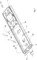
- Figure 1 is a schematic isometric view of an embodiment of a linear guide 1 with a rail element 2 and a carriage 31. The same linear guide is in a side plan view in Figure 2 shown.
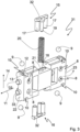
- Figure 3 shows the carriage 31 in an exploded view.
- the carriage 31 and the rail element 2 are mounted on one another so that they can be displaced relative to one another.
- the rail element 2 is C-shaped in cross section.
- the rail element 2 has two legs 3, 4. Each of the two legs 3, 4 has a tread 5, 6, with the two treads 5, 6 pointing towards each other.
- the two legs 3, 4 are connected to one another with a rail back 28.
- the carriage 31 comprises a base body 7, which in the illustrated embodiment is made of plastic by injection molding. Holes 8 are provided in the base body 7 in order to screw elements that are not part of the actual linear guide, such as a drawer in a motor vehicle, onto the base body 7 of the slide 31.
- a total of four balls 9 are accommodated as rolling elements in corresponding recesses 10 on the base body 7.
- these bearing balls 9 roll on the running surfaces 5, 6 of the two legs 3, 4 of the rail element 2 or slide on these running surfaces 5, 6.
- the balls 9 are on the base body 7 of the slide 31 in the manner of a rolling body cage or ball cage recorded. Ie the base body 7 defines the position of the balls 9 in the extension direction 11.
- the balls 9 are accommodated within the recesses 10 in holes 12 in the side wall surfaces 13 of the base body 7, so that the balls 9 have a maximum circular line contact with the Base body 7 on its right and left sides, but no full-surface frictional engagement with the base body 7.
- This construction leads to the balls rolling on the running surfaces 5, 6 of the rail element 2 with little rolling friction despite their guidance on the slide 31.
- This storage of the balls 9 on the base body 7 of the carriage 31 also results in the balls 9 having play in the vertical direction 14, so that the position of the carriage 31 in the vertical direction is not completely fixed.
- the vertical direction 14 is understood to mean a direction parallel to the rail back 28 and perpendicular to the extension direction 11.
- the carriage 31 has two sliding elements 15, 16.
- Each of the two sliding elements 15, 16 has a sliding surface 32, which, when the carriage 31 is installed, slides on one of the running surfaces 5, 6 of the rail element 2 and provides a defined sliding friction between the carriage 7 and the rail element 2.
- each sliding element 16 has two cylindrical guide pins 17. These guide pins 17 engage in two hollow cylindrical bearing bushes 18 in the base body 7 of the slide 31. In this way, the sliding elements 15, 16 are mounted on the base body 7 of the slide 31 so that they can move in the vertical direction 14, while the combination of guide pins 17 and bearing bushes 18 provides guidance in the extension direction 11.
- each of the sliding elements 15 has a spring receptacle 19 in the form of a cylindrical pin.
- a spring element in the form of a spiral spring 20 is also provided on the carriage 31.
- This spiral spring 20 is accommodated in a guide bushing 21 in the side wall of the base body 7 of the carriage 31, the guide bushing 21 for the spiral spring 20 extending in the vertical direction 14 of the carriage 31.
- the guide bushing 21 guides the spiral spring in a direction parallel to the extension direction. In the vertical direction 14, however, the spiral spring 20 is mounted floating in the bushing 21.
- the receiving pin 19 engages in the spiral spring 20. Therefore, the spiral spring 20 biases the two sliding elements 15 with exactly the same spring force in the direction of the two running surfaces 5, 6 of the rail element 2.
- the spring force which acts on the sliding elements and thus on the running surfaces 5, 6 of the rail element 2, is independent of the exact position of the carriage 31 in the vertical direction 14 relative to the rail element 2.
- Two cylindrical release locks or projections 33 are provided on both end faces 22, 23 of the base body 7 of the slide 31. If the carriage 31 reaches one or the other end of the rail element 2, the release locks 33 engage with it corresponding hollow cylindrical recesses 24 in end stop tabs 25 of the rail element 2. In both end positions, the carriage 31 is secured by the engagement of the release locks 33 in the complementary recesses 24 in the tabs 25.
- the linear guide 1 according to Figures 1 to 3 a catch, the catch consisting of a projection 34 on the rail element 2 and a catch element 35.
- the locking element 35 is in the rear view of a base body 7 of a carriage 31 Figure 6 shown.
- the locking element 35 is arranged on the side of the base body 7 of the carriage 31 facing the back of the rail 28.
- the locking element 35 is a projecting plastic section of the base body 7 of the carriage 31.
- the locking element 35 is arranged in the vertical direction 14 at the same position as the projection 34 on the back of the rail 28.
- the projection 34 is designed so that it is in the gap 29 formed between the treads 5, 6 protrudes.
- the projection 34 deforms the locking element 35 elastically and in cooperation the projection 34 and the locking element set the position of the slide 31 in the extension direction 11 by locking. The user can only move the carriage 31 further once the locking force provided by the locking element has been overcome.
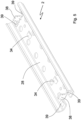
- Figure 4 shows an alternative embodiment of the linear guide 1, which differs from the embodiment according to the design of the release lock Figures 1 to 3 differs.
- the release lock is formed by two L-shaped recesses 26 in the end faces 22, 23 of the base body 7 of the slide 31.
- the rail element 2 in turn has two L-shaped retaining tabs 27 at each end as part of the release lock.
- the holding tabs 27 fit complementary into the recesses 26 in the base body 7 of the carriage 31.
- the rail element 2 is made from a bent sheet steel, so that the retaining tabs 27 are formed by partially punching out or cutting and bending the retaining tabs 27 relative to the rail back 28.
- the holding tabs 27 are bent so that they protrude into the space 29 between the running surfaces 5, 6 of the rail element 2.
- a first leg 36 of the L-shaped retaining tab 27 extends essentially perpendicular to the rail back 28 and a second leg 37 extends essentially parallel to the rail back 28.
- the holding tabs 27 on the one hand and the recesses 26 in the base body 7 of the carriage 31 on the other hand are arranged in such a way that when the respective end of the rail element 2 is reached, the holding tabs 27 engage in the recesses 26 and in this way the ones parallel to the back of the rail 28 Legs 37 of the retaining tabs 27 effectively prevent the carriage 31 from being untied from the rail element 2 in a direction perpendicular to the extension direction 11 and perpendicular to the vertical direction 14.
- the interaction of the holding tabs 27 with the recesses 26 also forms an end stop for the carriage when it reaches the end positions on the rail element 2.
- Figure 5 shows an alternative embodiment of the rail element 2 without a release lock but with an end stop for the carriage when the end position of the carriage is reached.
- the end stop is formed on the rail side by a stop in the form of a stop tab 38 bent perpendicularly relative to the back of the rail.
- a cap (not shown) made of an elastically deformable material is placed on this stop tab. In this way, the carriage hitting the stop tab 38 is dampened.
- the stop tab 38 can absorb all the forces introduced by the carriage. However, overload situations can occur in which the forces introduced by the carriage onto the stop tab 38 in the pull-out direction 11 would lead to the stop tab 38 bending.
- a pair of retaining tabs 39 are arranged at each end of the rail member 2.
- the retaining tabs are also partially punched out of the material of the rail element and bent relative to the back of the rail.
- the holding tabs 39 form an angle of less than 90° with the back of the rail 28 and their bent ends point towards the carriage. Due to this construction, the holding tabs 39 can absorb significantly higher forces than the stop tabs 38, which are aligned at an angle of approximately 90 ° to the back of the rail 28.
- the stop tabs with their respective dampers produce a pleasant, dampened feel when the end of the sliding movement of the carriage relative to the rail element is reached 2.
- the carriage 2 the damping element, the stop tab 38 and the holding tabs 39 are positioned and shaped in such a way that only when one is exceeded the damping element strikes the carriage 31 against the retaining tabs 39 with a predetermined force. Therefore, only in the event of an overload does the carriage 31 hit the rail element 2 hard.
Claims (12)
- Glissière (31) pour un guide linéaire (1) comprenant la glissière (31) et un élément rail (2) avec deux surfaces de roulement (5, 6) orientées l'une vers l'autre, la glissière (31) comprenantune partie principale (7) etune pluralité de corps de roulement (9),la pluralité de corps de roulement (9) étant reçue sur la partie principale (7) de sorte que la pluralité de corps de roulement (9) puisse rouler au moins sur les deux surfaces de roulement (5, 6) ou effectuer un mouvement de coulissement par rapport aux deux surfaces de roulement (5, 6),la partie principale (7) définissant une position de chacun de la pluralité de corps de roulement (9) dans une direction de retrait (11) par rapport à la partie principale (7),caractérisée en ce quela glissière comprend en outredeux éléments coulissants (15, 16) etun élément ressort (20),chacun des deux éléments coulissants (15, 16) étant monté mobile sur la partie principale dans une direction verticale (14) perpendiculaire à la direction de retrait (11), de sorte que chacun des deux éléments coulissants (15, 16) puisse être mis en prise par frottement avec l'une des surfaces de roulement (5, 6), etl'élément ressort (20) étant monté sur la partie principale (7) de sorte que l'élément ressort (20) sollicite les deux éléments coulissants (15, 16) à distance l'un de l'autre dans la direction verticale.
- Glissière (31) selon la revendication précédente, l'élément ressort (20) étant monté flottant sur la partie principale (7) dans la direction verticale (14).
- Glissière (31) selon l'une quelconque des revendications précédentes, chacun des deux éléments coulissants (15, 16) étant agencé dans la direction de retrait (11), de préférence de manière symétrique, entre deux corps de roulement (9).
- Glissière (31) selon l'une quelconque des revendications précédentes, chacun des deux éléments coulissants (15, 16) comprenant une section en forme de T, une barre transversale (32) de la section en forme de T pouvant être mise en prise par frottement avec une surface de roulement (5, 6) de l'élément rail (2) et une barre verticale (19) recevant l'élément ressort (20).
- Glissière (31) selon l'une quelconque des revendications précédentes, chacun des deux éléments coulissants (15, 16) comprenant au moins une broche de guidage (17), de préférence cylindrique, la broche de guidage (17) venant en prise respectivement dans une douille de guidage (21), de préférence cylindrique creuse, dans la partie principale (7) de la glissière (31), de sorte que chacun des deux éléments coulissants (15, 16) subisse un guidage dans la direction de retrait (11), alors qu'il est monté flottant dans la direction verticale (14).
- Glissière (31) selon l'une quelconque des revendications précédentes, l'élément élastique (20) étant un ressort hélicoïdal.
- Glissière (31) selon l'une quelconque des revendications précédentes, la partie principale (7) étant fabriquée en plastique, de préférence d'un seul tenant.
- Guide linéaire (1) comprenantun élément rail (2) avec deux surfaces de roulement (5, 6) orientées l'une vers l'autre, etune glissière (31) selon l'une quelconque des revendications précédentes,la pluralité de corps de roulement (9) étant reçue sur la partie principale (7) de sorte que la pluralité de corps de roulement (9) roule sur les surfaces de roulement (5, 6) ou effectue un mouvement de coulissement par rapport aux surfaces de roulement (5, 6) de sorte que la glissière (31) et l'élément rail (2) puissent être déplacés linéairement l'un par rapport à l'autre dans la direction de retrait (11),chacun des deux éléments coulissants (15, 16) étant mis en prise par frottement avec l'une des surfaces de roulement (5, 6).
- Guide linéaire (1) selon la revendication précédente, l'élément rail (2) comprenant une saillie (34) et la partie principale (7) comprenant une section d'encliquetage (35),la saillie (34) étant agencée et conçue de sorte qu'elle pénètre dans un espace intermédiaire (29) entre les deux surfaces de roulement (5, 6), la section d'encliquetage (35) étant déformable élastiquement dans une direction perpendiculaire à la direction de retrait (11), etla section d'encliquetage (35) étant agencée de sorte qu'elle soit mise en prise par frottement avec la saillie (34) dans une position de la glissière (31) dans la direction de retrait (11) par rapport à l'élément rail (2).
- Guide linéaire (1) selon la revendication 8 ou 9,au moins l'élément rail (2) comprenant une patte de retenue (27, 39) au moins à une première extrémité dans la direction de retrait (11) etla partie principale (7) de la glissière (31) comprenant un évidement (12, 26) dans une face frontale (22, 23) de la partie principale (7),la patte de retenue (27, 39) faisant saillie dans l'espace (29) entre les deux surfaces de roulement (5, 6), etla patte de retenue (27, 39) et l'évidement (12, 26) étant conçus et agencés de sorte que la patte de retenue (27, 39) vienne en prise dans l'évidement (12, 26) dans la partie principale (7) de la glissière (31) lorsque la glissière (31) atteint la première extrémité, de sorte que la glissière (31) ne puisse pas être détachée de l'élément rail (2) dans une direction perpendiculaire à la direction de retrait (11) et perpendiculaire à la direction verticale (14), oul'élément rail (2) comprenant au moins à la première extrémité une patte (25) s'étendant perpendiculairement à la direction de retrait (11) de l'élément rail (2), la patte (25) comprenant un évidement (24), etla glissière (31) comprenant sur sa face frontale (22, 23) une saillie (33) correspondant à l'évidement (24), etl'évidement (24) et la saillie (33) étant conçus et agencés de sorte que la saillie (33) vienne en prise dans l'évidement (33) dans la patte (25) lorsque la glissière (31) atteint la première extrémité, de sorte que la glissière (31) ne puisse pas être détachée de l'élément rail (2) dans une direction perpendiculaire à la direction de retrait (11) et perpendiculaire à la direction verticale (14).
- Guide linéaire (1) selon l'une quelconque des revendications 8 à 10,l'élément rail (2) comprenant un dos de rail (28),l'élément rail (2) comprenant une languette de retenue (27, 39) au moins à une première extrémité dans la direction de retrait (11),la patte de retenue (27, 39) étant fléchie par rapport au dos du rail (28) de sorte que la patte de retenue (27, 39) fasse saillie dans l'espace (29) entre les deux surfaces de roulement (5, 6),la patte de retenue (27, 39) et la partie principale (7) étant conçues et agencées de sorte que la partie principale (7) vienne en butée contre la patte de retenue (27, 39) lorsque la première extrémité est atteinte, etla patte de retenue (27, 39) étant de préférence fléchie par rapport au dos de rail (28) de sorte que la patte de retenue (27, 39) forme un angle inférieur à 90° avec le dos de rail (28).
- Guide linéaire (1) selon la revendication 10 ou 11,une butée (38) étant prévue à la première extrémité de l'élément rail (2) en plus de la patte de retenue (27, 39),un élément d'amortissement déformable élastiquement étant prévu sur la glissière (31) ou sur la butée (38),la glissière (31), l'élément d'amortissement et la butée (38) étant conçus et agencés de sorte que lorsque la première extrémité est atteinte, la glissière (31) vienne en prise avec l'élément d'amortissement et l'élément d'amortissement vienne en prise avec la butée (38), de sorte qu'un déplacement de retrait de la glissière (31) par rapport à l'élément rail (2) soit freiné, etla glissière (2), l'élément d'amortissement, la butée (38) et la patte de retenue (27, 39) étant conçus et agencés de sorte que la glissière (31) n'entre en contact avec la patte de retenue (27, 39) qu'en cas de dépassement d'une force prescrite par l'élément d'amortissement.
Applications Claiming Priority (2)
| Application Number | Priority Date | Filing Date | Title |
|---|---|---|---|
| DE102020110563.0A DE102020110563A1 (de) | 2020-04-17 | 2020-04-17 | Schlitten für eine Linearführung und Linearführung mit einem solchen Schlitten |
| PCT/EP2021/059127 WO2021209301A1 (fr) | 2020-04-17 | 2021-04-08 | Glissière pour guide linéaire, et guide linéaire doté d'une telle glissière |
Publications (3)
| Publication Number | Publication Date |
|---|---|
| EP4136360A1 EP4136360A1 (fr) | 2023-02-22 |
| EP4136360C0 EP4136360C0 (fr) | 2024-02-14 |
| EP4136360B1 true EP4136360B1 (fr) | 2024-02-14 |
Family
ID=75529979
Family Applications (1)
| Application Number | Title | Priority Date | Filing Date |
|---|---|---|---|
| EP21718816.8A Active EP4136360B1 (fr) | 2020-04-17 | 2021-04-08 | Glissière pour guide linéaire, et guide linéaire doté d'une telle glissière |
Country Status (5)
| Country | Link |
|---|---|
| US (1) | US20230160424A1 (fr) |
| EP (1) | EP4136360B1 (fr) |
| CN (1) | CN115427696A (fr) |
| DE (1) | DE102020110563A1 (fr) |
| WO (1) | WO2021209301A1 (fr) |
Families Citing this family (2)
| Publication number | Priority date | Publication date | Assignee | Title |
|---|---|---|---|---|
| DE102022120080A1 (de) | 2022-08-09 | 2024-02-15 | Accuride International Gmbh | Schlitten für ein lineares Führungssystem und lineares Führungssystem mit einem solchen Schlitten |
| DE102022120440A1 (de) | 2022-08-12 | 2024-02-15 | Accuride International Gmbh | Schlitten für ein lineares Führungssystem und lineares Führungssystem mit einem solchen Schlitten |
Family Cites Families (5)
| Publication number | Priority date | Publication date | Assignee | Title |
|---|---|---|---|---|
| DE4325045C2 (de) | 1993-07-26 | 1996-10-10 | Haff & Schneider Gmbh & Co Ohg | Geradführung für insbesondere Werkzeugmaschinen |
| DE29803210U1 (de) | 1998-02-24 | 1998-04-16 | Hettich Paul Gmbh & Co | Auszugsführung |
| DE202009001962U1 (de) * | 2008-11-03 | 2010-04-01 | Paul Hettich Gmbh & Co. Kg | Auszugsführung |
| DE102014220049A1 (de) | 2014-10-02 | 2016-04-07 | Schock Metallwerk Gmbh | Führungsvorrichtung |
| DE202015106016U1 (de) | 2015-11-09 | 2017-02-13 | Accuride International Gmbh | Crash-Verriegelung |
-
2020
- 2020-04-17 DE DE102020110563.0A patent/DE102020110563A1/de active Pending
-
2021
- 2021-04-08 WO PCT/EP2021/059127 patent/WO2021209301A1/fr unknown
- 2021-04-08 EP EP21718816.8A patent/EP4136360B1/fr active Active
- 2021-04-08 US US17/919,298 patent/US20230160424A1/en active Pending
- 2021-04-08 CN CN202180028344.1A patent/CN115427696A/zh active Pending
Also Published As
| Publication number | Publication date |
|---|---|
| EP4136360C0 (fr) | 2024-02-14 |
| WO2021209301A1 (fr) | 2021-10-21 |
| CN115427696A (zh) | 2022-12-02 |
| EP4136360A1 (fr) | 2023-02-22 |
| DE102020110563A1 (de) | 2021-10-21 |
| US20230160424A1 (en) | 2023-05-25 |
Similar Documents
| Publication | Publication Date | Title |
|---|---|---|
| EP0743031B1 (fr) | Glissière pour tiroir | |
| EP4136360B1 (fr) | Glissière pour guide linéaire, et guide linéaire doté d'une telle glissière | |
| EP1474307B1 (fr) | Systeme de reglage longitudinal pour siege de vehicule | |
| EP3393847B1 (fr) | Cage de roulement et paire de rails de siège pour siège de véhicule | |
| EP1316465A1 (fr) | Dispositif d'arrêt avec goupilles de blocage rainurées | |
| EP0588812B1 (fr) | Entrainement de broche pour un dispositif de reglage de sieges de vehicules | |
| DE102006007978B4 (de) | Teleskopführung mit Rastelement | |
| EP2983943A1 (fr) | Dispositif de réglage longitudinal d'un siège de véhicule et siège de véhicule | |
| EP3762252B1 (fr) | Systeme d'ajustement horizontal pour un siege de vehicule equipe d'un rail au sol, d'un rail de siege ajustable and d'une unite de blocage | |
| WO2017021383A1 (fr) | Dispositif de réglage longitudinal d'un siège de véhicule | |
| EP2086791A1 (fr) | Dispositif de réglage longitudinal pour un siège de véhicule automobile | |
| DE102006009304B3 (de) | Lenksäulenanordnung für Fahrzeuge | |
| EP2422647A1 (fr) | Colonne de meuble réglable en hauteur | |
| DE3030725A1 (de) | Laengsfuehrung, insbesondere fuer laengsverstelleinrichtungen von fahrzeugsitzen | |
| DE102015012411A1 (de) | Kopfstütze | |
| EP3724526B1 (fr) | Rail télescopique | |
| DE102005028871B4 (de) | Überrollschutzsystem für ein Kraftfahrzeug, insbesondere für ein Cabriolet | |
| DE2912363A1 (de) | Elektrischer schalter mit einer handhabe | |
| EP4280912A1 (fr) | Élément de meuble | |
| DE3822575C2 (fr) | ||
| DE102004062764A1 (de) | Rollenwagen | |
| DE102004001568B4 (de) | Teleskopschiene | |
| DE102008011620A1 (de) | Verstellbare Lenksäule für ein Kraftfahrzeug | |
| EP3569804A1 (fr) | Dispositif de guidage pour une porte coulissante | |
| EP4321765A1 (fr) | Chariot pour un système de guidage linéaire et système de guidage linéaire comprenant un tel chariot |
Legal Events
| Date | Code | Title | Description |
|---|---|---|---|
| STAA | Information on the status of an ep patent application or granted ep patent |
Free format text: STATUS: UNKNOWN |
|
| STAA | Information on the status of an ep patent application or granted ep patent |
Free format text: STATUS: THE INTERNATIONAL PUBLICATION HAS BEEN MADE |
|
| PUAI | Public reference made under article 153(3) epc to a published international application that has entered the european phase |
Free format text: ORIGINAL CODE: 0009012 |
|
| STAA | Information on the status of an ep patent application or granted ep patent |
Free format text: STATUS: REQUEST FOR EXAMINATION WAS MADE |
|
| 17P | Request for examination filed |
Effective date: 20221102 |
|
| AK | Designated contracting states |
Kind code of ref document: A1 Designated state(s): AL AT BE BG CH CY CZ DE DK EE ES FI FR GB GR HR HU IE IS IT LI LT LU LV MC MK MT NL NO PL PT RO RS SE SI SK SM TR |
|
| DAV | Request for validation of the european patent (deleted) | ||
| DAX | Request for extension of the european patent (deleted) | ||
| GRAP | Despatch of communication of intention to grant a patent |
Free format text: ORIGINAL CODE: EPIDOSNIGR1 |
|
| STAA | Information on the status of an ep patent application or granted ep patent |
Free format text: STATUS: GRANT OF PATENT IS INTENDED |
|
| INTG | Intention to grant announced |
Effective date: 20230901 |
|
| GRAS | Grant fee paid |
Free format text: ORIGINAL CODE: EPIDOSNIGR3 |
|
| GRAA | (expected) grant |
Free format text: ORIGINAL CODE: 0009210 |
|
| STAA | Information on the status of an ep patent application or granted ep patent |
Free format text: STATUS: THE PATENT HAS BEEN GRANTED |
|
| AK | Designated contracting states |
Kind code of ref document: B1 Designated state(s): AL AT BE BG CH CY CZ DE DK EE ES FI FR GB GR HR HU IE IS IT LI LT LU LV MC MK MT NL NO PL PT RO RS SE SI SK SM TR |
|
| REG | Reference to a national code |
Ref country code: GB Ref legal event code: FG4D Free format text: NOT ENGLISH |
|
| REG | Reference to a national code |
Ref country code: CH Ref legal event code: EP |
|
| REG | Reference to a national code |
Ref country code: DE Ref legal event code: R096 Ref document number: 502021002694 Country of ref document: DE |
|
| REG | Reference to a national code |
Ref country code: IE Ref legal event code: FG4D Free format text: LANGUAGE OF EP DOCUMENT: GERMAN |
|
| U01 | Request for unitary effect filed |
Effective date: 20240314 |
|
| U07 | Unitary effect registered |
Designated state(s): AT BE BG DE DK EE FI FR IT LT LU LV MT NL PT SE SI Effective date: 20240322 |