EP4136360B1 - Slide for a linear guide, and linear guide comprising such a slide - Google Patents
Slide for a linear guide, and linear guide comprising such a slide Download PDFInfo
- Publication number
- EP4136360B1 EP4136360B1 EP21718816.8A EP21718816A EP4136360B1 EP 4136360 B1 EP4136360 B1 EP 4136360B1 EP 21718816 A EP21718816 A EP 21718816A EP 4136360 B1 EP4136360 B1 EP 4136360B1
- Authority
- EP
- European Patent Office
- Prior art keywords
- slide
- rail
- rail element
- main part
- pull
- Prior art date
- Legal status (The legal status is an assumption and is not a legal conclusion. Google has not performed a legal analysis and makes no representation as to the accuracy of the status listed.)
- Active
Links
- 238000005096 rolling process Methods 0.000 claims description 45
- 238000013016 damping Methods 0.000 claims description 16
- 238000007667 floating Methods 0.000 claims description 6
- 229910052751 metal Inorganic materials 0.000 description 4
- 239000002184 metal Substances 0.000 description 4
- 229910000831 Steel Inorganic materials 0.000 description 3
- 238000010276 construction Methods 0.000 description 3
- 238000001746 injection moulding Methods 0.000 description 3
- 239000010959 steel Substances 0.000 description 3
- 238000005452 bending Methods 0.000 description 2
- 230000000295 complement effect Effects 0.000 description 2
- 238000006073 displacement reaction Methods 0.000 description 2
- 239000000463 material Substances 0.000 description 2
- 229910052782 aluminium Inorganic materials 0.000 description 1
- XAGFODPZIPBFFR-UHFFFAOYSA-N aluminium Chemical compound [Al] XAGFODPZIPBFFR-UHFFFAOYSA-N 0.000 description 1
- 239000011324 bead Substances 0.000 description 1
- 238000007373 indentation Methods 0.000 description 1
- 238000009434 installation Methods 0.000 description 1
- 230000003993 interaction Effects 0.000 description 1
- 230000036316 preload Effects 0.000 description 1
- 238000004080 punching Methods 0.000 description 1
- 239000013585 weight reducing agent Substances 0.000 description 1
Images


Classifications
-
- A—HUMAN NECESSITIES
- A47—FURNITURE; DOMESTIC ARTICLES OR APPLIANCES; COFFEE MILLS; SPICE MILLS; SUCTION CLEANERS IN GENERAL
- A47B—TABLES; DESKS; OFFICE FURNITURE; CABINETS; DRAWERS; GENERAL DETAILS OF FURNITURE
- A47B88/00—Drawers for tables, cabinets or like furniture; Guides for drawers
- A47B88/40—Sliding drawers; Slides or guides therefor
- A47B88/473—Braking devices, e.g. linear or rotational dampers or friction brakes; Buffers; End stops
-
- F—MECHANICAL ENGINEERING; LIGHTING; HEATING; WEAPONS; BLASTING
- F16—ENGINEERING ELEMENTS AND UNITS; GENERAL MEASURES FOR PRODUCING AND MAINTAINING EFFECTIVE FUNCTIONING OF MACHINES OR INSTALLATIONS; THERMAL INSULATION IN GENERAL
- F16C—SHAFTS; FLEXIBLE SHAFTS; ELEMENTS OR CRANKSHAFT MECHANISMS; ROTARY BODIES OTHER THAN GEARING ELEMENTS; BEARINGS
- F16C29/00—Bearings for parts moving only linearly
- F16C29/007—Hybrid linear bearings, i.e. including more than one bearing type, e.g. sliding contact bearings as well as rolling contact bearings
-
- A—HUMAN NECESSITIES
- A47—FURNITURE; DOMESTIC ARTICLES OR APPLIANCES; COFFEE MILLS; SPICE MILLS; SUCTION CLEANERS IN GENERAL
- A47B—TABLES; DESKS; OFFICE FURNITURE; CABINETS; DRAWERS; GENERAL DETAILS OF FURNITURE
- A47B88/00—Drawers for tables, cabinets or like furniture; Guides for drawers
- A47B88/40—Sliding drawers; Slides or guides therefor
- A47B88/437—Rollers for slides or guides
-
- F—MECHANICAL ENGINEERING; LIGHTING; HEATING; WEAPONS; BLASTING
- F16—ENGINEERING ELEMENTS AND UNITS; GENERAL MEASURES FOR PRODUCING AND MAINTAINING EFFECTIVE FUNCTIONING OF MACHINES OR INSTALLATIONS; THERMAL INSULATION IN GENERAL
- F16C—SHAFTS; FLEXIBLE SHAFTS; ELEMENTS OR CRANKSHAFT MECHANISMS; ROTARY BODIES OTHER THAN GEARING ELEMENTS; BEARINGS
- F16C29/00—Bearings for parts moving only linearly
- F16C29/04—Ball or roller bearings
- F16C29/045—Ball or roller bearings having rolling elements journaled in one of the moving parts
- F16C29/046—Ball or roller bearings having rolling elements journaled in one of the moving parts with balls journaled in pockets
-
- F—MECHANICAL ENGINEERING; LIGHTING; HEATING; WEAPONS; BLASTING
- F16—ENGINEERING ELEMENTS AND UNITS; GENERAL MEASURES FOR PRODUCING AND MAINTAINING EFFECTIVE FUNCTIONING OF MACHINES OR INSTALLATIONS; THERMAL INSULATION IN GENERAL
- F16C—SHAFTS; FLEXIBLE SHAFTS; ELEMENTS OR CRANKSHAFT MECHANISMS; ROTARY BODIES OTHER THAN GEARING ELEMENTS; BEARINGS
- F16C29/00—Bearings for parts moving only linearly
- F16C29/04—Ball or roller bearings
- F16C29/048—Ball or roller bearings with thin walled races, e.g. tracks of sheet metal
-
- F—MECHANICAL ENGINEERING; LIGHTING; HEATING; WEAPONS; BLASTING
- F16—ENGINEERING ELEMENTS AND UNITS; GENERAL MEASURES FOR PRODUCING AND MAINTAINING EFFECTIVE FUNCTIONING OF MACHINES OR INSTALLATIONS; THERMAL INSULATION IN GENERAL
- F16C—SHAFTS; FLEXIBLE SHAFTS; ELEMENTS OR CRANKSHAFT MECHANISMS; ROTARY BODIES OTHER THAN GEARING ELEMENTS; BEARINGS
- F16C29/00—Bearings for parts moving only linearly
- F16C29/10—Arrangements for locking the bearings
-
- F—MECHANICAL ENGINEERING; LIGHTING; HEATING; WEAPONS; BLASTING
- F16—ENGINEERING ELEMENTS AND UNITS; GENERAL MEASURES FOR PRODUCING AND MAINTAINING EFFECTIVE FUNCTIONING OF MACHINES OR INSTALLATIONS; THERMAL INSULATION IN GENERAL
- F16C—SHAFTS; FLEXIBLE SHAFTS; ELEMENTS OR CRANKSHAFT MECHANISMS; ROTARY BODIES OTHER THAN GEARING ELEMENTS; BEARINGS
- F16C29/00—Bearings for parts moving only linearly
- F16C29/12—Arrangements for adjusting play
- F16C29/123—Arrangements for adjusting play using elastic means
-
- F—MECHANICAL ENGINEERING; LIGHTING; HEATING; WEAPONS; BLASTING
- F16—ENGINEERING ELEMENTS AND UNITS; GENERAL MEASURES FOR PRODUCING AND MAINTAINING EFFECTIVE FUNCTIONING OF MACHINES OR INSTALLATIONS; THERMAL INSULATION IN GENERAL
- F16C—SHAFTS; FLEXIBLE SHAFTS; ELEMENTS OR CRANKSHAFT MECHANISMS; ROTARY BODIES OTHER THAN GEARING ELEMENTS; BEARINGS
- F16C29/00—Bearings for parts moving only linearly
- F16C29/12—Arrangements for adjusting play
- F16C29/126—Arrangements for adjusting play using tapered surfaces or wedges
-
- A—HUMAN NECESSITIES
- A47—FURNITURE; DOMESTIC ARTICLES OR APPLIANCES; COFFEE MILLS; SPICE MILLS; SUCTION CLEANERS IN GENERAL
- A47B—TABLES; DESKS; OFFICE FURNITURE; CABINETS; DRAWERS; GENERAL DETAILS OF FURNITURE
- A47B2210/00—General construction of drawers, guides and guide devices
- A47B2210/0002—Guide construction for drawers
- A47B2210/0029—Guide bearing means
- A47B2210/0032—Balls
- A47B2210/0035—Balls cages therefor, e.g. for telescopic slides
-
- F—MECHANICAL ENGINEERING; LIGHTING; HEATING; WEAPONS; BLASTING
- F16—ENGINEERING ELEMENTS AND UNITS; GENERAL MEASURES FOR PRODUCING AND MAINTAINING EFFECTIVE FUNCTIONING OF MACHINES OR INSTALLATIONS; THERMAL INSULATION IN GENERAL
- F16C—SHAFTS; FLEXIBLE SHAFTS; ELEMENTS OR CRANKSHAFT MECHANISMS; ROTARY BODIES OTHER THAN GEARING ELEMENTS; BEARINGS
- F16C2226/00—Joining parts; Fastening; Assembling or mounting parts
- F16C2226/10—Force connections, e.g. clamping
-
- F—MECHANICAL ENGINEERING; LIGHTING; HEATING; WEAPONS; BLASTING
- F16—ENGINEERING ELEMENTS AND UNITS; GENERAL MEASURES FOR PRODUCING AND MAINTAINING EFFECTIVE FUNCTIONING OF MACHINES OR INSTALLATIONS; THERMAL INSULATION IN GENERAL
- F16C—SHAFTS; FLEXIBLE SHAFTS; ELEMENTS OR CRANKSHAFT MECHANISMS; ROTARY BODIES OTHER THAN GEARING ELEMENTS; BEARINGS
- F16C2314/00—Personal or domestic articles, e.g. household appliances such as washing machines, dryers
- F16C2314/70—Furniture
- F16C2314/72—Drawers
Definitions
- the present invention relates to a slide for a linear guide, the linear guide comprising such a slide and a rail element with two running surfaces pointing towards one another, the slide having a base body and a plurality of rolling elements, the plurality of rolling elements being accommodated on the base body in this way that the plurality of rolling bodies can be rolled on the second running surfaces of the rail element or carry out a sliding movement relative to the two running surfaces, the base body defining a position of each of the plurality of rolling bodies in an extension direction relative to the base body.
- the present invention also relates to a linear guide with such a carriage and a rail element.
- Linear guides with a slide and a rail element with rolling bodies fixed to the slide between the slide and the running surfaces of the rail element, are known from the prior art. For example from the DE 20 2009 001962 U1 . They are used in various household appliances, but also in automobile construction and many other applications.
- rolling elements are arranged between the rail element and the carriage, with the rolling elements rolling on the surface of the running surfaces of the rail element during a relative movement of the carriage and the rail element or a sliding movement relative to the surface of the running surfaces carry out.
- the resulting rolling and/or sliding friction is less than direct sliding friction between the carriage and the rail element.
- the position of the carriage relative to the rail element cannot be precisely defined by the rolling elements.
- a slide for a linear guide of the type mentioned is proposed, the slide further having two sliding elements and a spring element, each of the two sliding elements being movably mounted on the base body in a vertical direction perpendicular to the extension direction, so that each of the two sliding elements can each be brought into frictional engagement with one of the running surfaces, and wherein the spring element is mounted on the base body in such a way that the spring element biases both sliding elements away from one another in the vertical direction.
- the basic idea of the present invention is to provide at least two sliding elements on the carriage in addition to the plurality of rolling elements, which are biased against the running surfaces of the rail element by a spring element also provided on the carriage.
- a spring element also provided on the carriage.
- the two sliding elements and the spring element form a functional unit, since exactly one spring element biases the two sliding elements away from each other and thus onto the running surfaces of the rail element.
- the present invention relates first of all to such a slide for a linear guide, independent of the rail element necessary for the complete linear guide.
- the base body of the carriage is made of metal or plastic.
- an embodiment of the base body made of plastic makes it possible to produce the base body cost-effectively, preferably in one piece (in one piece), for example by injection molding, in large quantities. Plastic also enables weight reduction.
- elements such as a drawer in a motor vehicle
- elements are mounted on the base body.
- the basic body points to this In one embodiment, threaded holes or holes through which screws reach for fastening further elements.
- a rolling body in the sense of the present application is understood to be a rotating body which, as an element of a guide, significantly reduces the friction between the carriage and the rail element and thus facilitates a relative movement of the carriage with respect to the rail element.
- Rolling elements are, for example, balls, rollers, barrels, needles or cones.
- the base body of the carriage also serves as a cage for the rolling bodies, in that the base body determines the positions of the rolling bodies in the extension direction relative to the base body.
- the pull-out direction refers to the direction in which the carriage can be linearly displaced relative to the rail element when installed.
- the vertical direction is understood to be a direction perpendicular to the extension direction, which extends essentially parallel to a rail back of the rail element.
- the vertical direction is parallel to the spring force that the spring element exerts on the two sliding elements.
- the spring element and preferably also the sliding elements are mounted on the base body in a floating manner in the vertical direction. This means that the spring element is supported in the vertical direction exclusively on the two sliding elements, but not on the base body of the slide. In this way, the spring force that is exerted on the two sliding elements is independent of the exact position of the base body in the vertical direction. In particular, in one embodiment, the spring force exerted on the two sliding elements is the same size.
- the spring force exerted by the spring element on the sliding elements can be adjusted.
- Such an adjustability of the spring force can be realized both with a fixed mounting of the spring element on the base body and with a floating mounting of the spring element relative to the base body.
- An adjustability of the spring element means that the spring force can be varied and adjusted either before the carriage is mounted or when the carriage is already mounted on the rail element.
- the adjustability of the spring force is realized in that for a given distance between the two Running surfaces of the rail element, the distance between the abutments for the spring element on the two sliding elements is adjustable. In this way, the installation space available for the spring between the two sliding elements in the vertical direction can be adjusted and the spring preload of the sliding elements can be varied.
- each of the two sliding elements is arranged between two rolling elements in the extension direction, preferably symmetrically. If rolling elements are provided to the left and right of the respective sliding element in the extension direction, the sliding element also fulfills a position-stabilizing function with regard to the positioning of the base body of the carriage relative to the rail element.
- the carriage has exactly four rolling elements, each of the two sliding elements being arranged between two rolling elements.
- each of the two sliding elements is arranged symmetrically between at least two rolling elements.
- the spring element is a spiral spring. Coil springs can be manufactured easily and cost-effectively and installed with a defined spring force. In one embodiment of the invention, the spiral spring is supported on both one and the other sliding element and presses them away from each other towards the running surfaces of the rail element. In addition, in one embodiment, the spring element does not introduce any forces into the base body of the slide.
- the two sliding elements are made of plastic, preferably by injection molding.
- the sliding element has a T-shaped section, the crossbar of the T-shape forming that part of the sliding element which comes into sliding engagement with the respective running surface of the rail element.
- the vertical bar serves to hold the spring element. If the spring element is a spiral spring, in one embodiment the vertical bar extends into the interior of the spiral spring.
- the guiding element has at least one, but in particular two, preferably cylindrical, guide pins.
- This guide pin engages in one, preferably hollow cylindrical, guide bushing in the base body of the slide, so that the sliding element is guided in the extension direction while it is floating in the vertical direction.
- At least one of the above-mentioned tasks is also achieved by a linear guide, the linear guide comprising a rail element with two running surfaces pointing towards one another and a carriage in one of the embodiments as described above.
- the plurality of rolling elements is accommodated on the base body in such a way that the plurality of rolling elements rolls on the running surfaces or carries out a sliding movement relative to the running surfaces, so that the carriage and the rail element can be displaced linearly relative to one another in the extension direction, each of the two sliding elements each having one the treads are in frictional engagement.
- a linear guide in the sense of the present invention is understood to mean any arrangement consisting of at least one carriage and at least one rail element, the carriage and the rail element being displaceable relative to one another along a linear path.
- a partial extension and a full extension each represent an embodiment of a linear guide.
- the rail element has a projection and the base body has a latching section.
- the projection is arranged and designed in such a way that it projects into an intermediate space between the two running surfaces of the rail element, the locking section being elastically deformable in a direction perpendicular to the extension direction and the locking section being arranged in such a way that it is in a position of the carriage is in frictional engagement with the projection in the extension direction relative to the rail element. In this way, the carriage can be locked relative to the rail element at one or more positions in the extension direction with little effort.
- the present application therefore also relates to a linear guide with a rail element with two running surfaces pointing towards each other and a carriage, the carriage having one Base body and a plurality of rolling bodies, wherein the plurality of rolling bodies is accommodated on the base body such that the plurality of rolling bodies roll on the second running surfaces of the rail element, the base body having a position of each of the plurality of rolling bodies in the extension direction relative to the base body, wherein the rail element has a projection and the base body has a latching section, the projection being arranged and designed in such a way that it projects into a space between the two running surfaces, the latching section being elastically deformable in a direction perpendicular to the extension direction and wherein the latching portion is arranged such that it is in frictional engagement with the projection in a position of the carriage in the extension direction relative to the rail element.
- the rail element is made at least in sections from metal, in particular from steel or aluminum, or from plastic.
- the rail element is a rail element made of steel
- the projection is realized as a bead or as an indentation in the rail back of the rail element.
- an embodiment in which the rail element has a projection is suitable for implementation with a slide that has a base body made of plastic.
- the latching section is elastically deformable in a direction perpendicular to the extension direction and perpendicular to the vertical direction.
- the latching section can be realized, for example, by a thinned plastic section, which can be elastically deformed.
- the rail element has a retaining tab at least at one end in the pull-out direction and the base body of the carriage has a recess in an end face of the base body, the retaining tab protruding into the space between the two running surfaces and the retaining tab and the recess is designed and arranged in such a way that the retaining tab engages in the recess in the base body of the carriage when the carriage reaches the first end, so that the carriage cannot be detached from the rail element in a direction perpendicular to the extension direction and perpendicular to the vertical direction .
- the release lock is particularly suitable for linear guides with high dynamics or for carrying large loads.
- the rail element has a tab at the first end which extends perpendicular to the extension direction of the rail element, the tab having a recess and the carriage having a projection corresponding to the recess on its end face and the recess and the projection being such are designed and arranged so that the projection engages in the recess in the tab when the carriage reaches the first end, so that the carriage cannot be detached from the rail element in a direction perpendicular to the extension direction and perpendicular to the vertical direction.
- holding tab and hole forms a linear guide with a slide and a rail element, the slide having the hole and the rail element having the holding tab, as described in detail below, also an independent invention without the carriage necessarily having the characterizing features of independent claim 1 of this application.
- the present application therefore also relates to a linear guide with a rail element with two running surfaces pointing towards one another and a slide, the slide having a base body and a plurality of rolling elements, the plurality of rolling elements being accommodated on the base body in such a way that the plurality of rolling elements roll on the second running surfaces of the rail element, the base body defining a position of each of the plurality of rolling elements in the extension direction relative to the base body, at least the rail element having a retaining tab at least at a first end in the extension direction and the base body of the carriage Hole in an end face of the base body, wherein the retaining tab projects into the space between the two running surfaces and wherein the retaining tab and the hole are designed and arranged such that the retaining tab engages in the hole in the base body of the carriage when the carriage has the first end achieved, so that the carriage cannot be detached from the rail element in a direction perpendicular to the extension direction and perpendicular to the vertical direction, or the rail element has a tab at the first end which extend
- the rail element has a rail back, preferably made at least in sections from metal, the rail element having a retaining tab at least at a first end in the pull-out direction, the retaining strip being bent relative to the rail back in such a way that the retaining tab is in protrudes into the space between the two running surfaces, the retaining tab and the base body being designed and arranged in such a way that the base body abuts the retaining tab when it reaches the first end.
- a holding tab has the advantage that it can absorb high forces in the pull-out direction without the base body being able to bend or bend the holding tab in the pull-out direction.
- the retaining tab is bent relative to the back of the rail in such a way that the retaining tab forms an angle of less than 90° with the back of the rail.
- Such a design of the retaining tab is able to absorb large forces in the pull-out direction.
- the present application therefore also relates to a linear guide with a rail element with two running surfaces pointing towards one another and a slide, the slide having a base body and a plurality of rolling elements, the plurality of rolling elements being accommodated on the base body in such a way that the plurality of rolling elements roll on the second running surfaces of the rail element, the base body defining a position of each of the plurality of rolling elements in the extension direction relative to the base body, the rail element having a rail back, preferably at least partially made of metal, the rail element being at least on one in
- the first end has a holding tab in the pull-out direction, the holding strip being bent relative to the back of the rail in such a way that the holding tab projects into the space between the two running surfaces, the holding tab and the base body being designed and arranged in such a way that the base body reaches the first end abuts the retaining tab, and the retaining tab is preferably opposite the The back of the rail is bent so that the retaining tab forms an angle of less than 90° with the back
- a stop is provided at the first end of the rail element in addition to the retaining tab, as previously described in embodiments thereof, an elastically deformable damping element being provided on the carriage or on the stop, the carriage , the damping element and the stop are designed and arranged in such a way that when the first end is reached, the carriage comes into engagement with the damping element and the damping element with the stop, so that an extension movement of the carriage is braked relative to the rail element, and wherein the carriage, the damping element, the stop and the retaining tab are designed and arranged in such a way that the carriage comes into engagement with the retaining tab only when a force predetermined by the damping element is exceeded.
- Such an embodiment enables a comfortable end stop for the user of the linear guide when reaching the first end of the rail element, which is damped by the damping element.
- an overload stop is provided by the retaining tab when a force predetermined by the damping element is exceeded.
- this overload stop provides an effective limitation of the displacement path of the carriage relative to the rail element in the extension direction.
- the overload stop alternatively or additionally provides a release protection against the carriage being separated from the rail element.
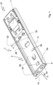
- Figure 1 is a schematic isometric view of an embodiment of a linear guide 1 with a rail element 2 and a carriage 31. The same linear guide is in a side plan view in Figure 2 shown.
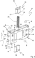
- Figure 3 shows the carriage 31 in an exploded view.
- the carriage 31 and the rail element 2 are mounted on one another so that they can be displaced relative to one another.
- the rail element 2 is C-shaped in cross section.
- the rail element 2 has two legs 3, 4. Each of the two legs 3, 4 has a tread 5, 6, with the two treads 5, 6 pointing towards each other.
- the two legs 3, 4 are connected to one another with a rail back 28.
- the carriage 31 comprises a base body 7, which in the illustrated embodiment is made of plastic by injection molding. Holes 8 are provided in the base body 7 in order to screw elements that are not part of the actual linear guide, such as a drawer in a motor vehicle, onto the base body 7 of the slide 31.
- a total of four balls 9 are accommodated as rolling elements in corresponding recesses 10 on the base body 7.
- these bearing balls 9 roll on the running surfaces 5, 6 of the two legs 3, 4 of the rail element 2 or slide on these running surfaces 5, 6.
- the balls 9 are on the base body 7 of the slide 31 in the manner of a rolling body cage or ball cage recorded. Ie the base body 7 defines the position of the balls 9 in the extension direction 11.
- the balls 9 are accommodated within the recesses 10 in holes 12 in the side wall surfaces 13 of the base body 7, so that the balls 9 have a maximum circular line contact with the Base body 7 on its right and left sides, but no full-surface frictional engagement with the base body 7.
- This construction leads to the balls rolling on the running surfaces 5, 6 of the rail element 2 with little rolling friction despite their guidance on the slide 31.
- This storage of the balls 9 on the base body 7 of the carriage 31 also results in the balls 9 having play in the vertical direction 14, so that the position of the carriage 31 in the vertical direction is not completely fixed.
- the vertical direction 14 is understood to mean a direction parallel to the rail back 28 and perpendicular to the extension direction 11.
- the carriage 31 has two sliding elements 15, 16.
- Each of the two sliding elements 15, 16 has a sliding surface 32, which, when the carriage 31 is installed, slides on one of the running surfaces 5, 6 of the rail element 2 and provides a defined sliding friction between the carriage 7 and the rail element 2.
- each sliding element 16 has two cylindrical guide pins 17. These guide pins 17 engage in two hollow cylindrical bearing bushes 18 in the base body 7 of the slide 31. In this way, the sliding elements 15, 16 are mounted on the base body 7 of the slide 31 so that they can move in the vertical direction 14, while the combination of guide pins 17 and bearing bushes 18 provides guidance in the extension direction 11.
- each of the sliding elements 15 has a spring receptacle 19 in the form of a cylindrical pin.
- a spring element in the form of a spiral spring 20 is also provided on the carriage 31.
- This spiral spring 20 is accommodated in a guide bushing 21 in the side wall of the base body 7 of the carriage 31, the guide bushing 21 for the spiral spring 20 extending in the vertical direction 14 of the carriage 31.
- the guide bushing 21 guides the spiral spring in a direction parallel to the extension direction. In the vertical direction 14, however, the spiral spring 20 is mounted floating in the bushing 21.
- the receiving pin 19 engages in the spiral spring 20. Therefore, the spiral spring 20 biases the two sliding elements 15 with exactly the same spring force in the direction of the two running surfaces 5, 6 of the rail element 2.
- the spring force which acts on the sliding elements and thus on the running surfaces 5, 6 of the rail element 2, is independent of the exact position of the carriage 31 in the vertical direction 14 relative to the rail element 2.
- Two cylindrical release locks or projections 33 are provided on both end faces 22, 23 of the base body 7 of the slide 31. If the carriage 31 reaches one or the other end of the rail element 2, the release locks 33 engage with it corresponding hollow cylindrical recesses 24 in end stop tabs 25 of the rail element 2. In both end positions, the carriage 31 is secured by the engagement of the release locks 33 in the complementary recesses 24 in the tabs 25.
- the linear guide 1 according to Figures 1 to 3 a catch, the catch consisting of a projection 34 on the rail element 2 and a catch element 35.
- the locking element 35 is in the rear view of a base body 7 of a carriage 31 Figure 6 shown.
- the locking element 35 is arranged on the side of the base body 7 of the carriage 31 facing the back of the rail 28.
- the locking element 35 is a projecting plastic section of the base body 7 of the carriage 31.
- the locking element 35 is arranged in the vertical direction 14 at the same position as the projection 34 on the back of the rail 28.
- the projection 34 is designed so that it is in the gap 29 formed between the treads 5, 6 protrudes.
- the projection 34 deforms the locking element 35 elastically and in cooperation the projection 34 and the locking element set the position of the slide 31 in the extension direction 11 by locking. The user can only move the carriage 31 further once the locking force provided by the locking element has been overcome.
- Figure 4 shows an alternative embodiment of the linear guide 1, which differs from the embodiment according to the design of the release lock Figures 1 to 3 differs.
- the release lock is formed by two L-shaped recesses 26 in the end faces 22, 23 of the base body 7 of the slide 31.
- the rail element 2 in turn has two L-shaped retaining tabs 27 at each end as part of the release lock.
- the holding tabs 27 fit complementary into the recesses 26 in the base body 7 of the carriage 31.
- the rail element 2 is made from a bent sheet steel, so that the retaining tabs 27 are formed by partially punching out or cutting and bending the retaining tabs 27 relative to the rail back 28.
- the holding tabs 27 are bent so that they protrude into the space 29 between the running surfaces 5, 6 of the rail element 2.
- a first leg 36 of the L-shaped retaining tab 27 extends essentially perpendicular to the rail back 28 and a second leg 37 extends essentially parallel to the rail back 28.
- the holding tabs 27 on the one hand and the recesses 26 in the base body 7 of the carriage 31 on the other hand are arranged in such a way that when the respective end of the rail element 2 is reached, the holding tabs 27 engage in the recesses 26 and in this way the ones parallel to the back of the rail 28 Legs 37 of the retaining tabs 27 effectively prevent the carriage 31 from being untied from the rail element 2 in a direction perpendicular to the extension direction 11 and perpendicular to the vertical direction 14.
- the interaction of the holding tabs 27 with the recesses 26 also forms an end stop for the carriage when it reaches the end positions on the rail element 2.
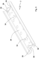
- Figure 5 shows an alternative embodiment of the rail element 2 without a release lock but with an end stop for the carriage when the end position of the carriage is reached.
- the end stop is formed on the rail side by a stop in the form of a stop tab 38 bent perpendicularly relative to the back of the rail.
- a cap (not shown) made of an elastically deformable material is placed on this stop tab. In this way, the carriage hitting the stop tab 38 is dampened.
- the stop tab 38 can absorb all the forces introduced by the carriage. However, overload situations can occur in which the forces introduced by the carriage onto the stop tab 38 in the pull-out direction 11 would lead to the stop tab 38 bending.
- a pair of retaining tabs 39 are arranged at each end of the rail member 2.
- the retaining tabs are also partially punched out of the material of the rail element and bent relative to the back of the rail.
- the holding tabs 39 form an angle of less than 90° with the back of the rail 28 and their bent ends point towards the carriage. Due to this construction, the holding tabs 39 can absorb significantly higher forces than the stop tabs 38, which are aligned at an angle of approximately 90 ° to the back of the rail 28.
- the stop tabs with their respective dampers produce a pleasant, dampened feel when the end of the sliding movement of the carriage relative to the rail element is reached 2.
- the carriage 2 the damping element, the stop tab 38 and the holding tabs 39 are positioned and shaped in such a way that only when one is exceeded the damping element strikes the carriage 31 against the retaining tabs 39 with a predetermined force. Therefore, only in the event of an overload does the carriage 31 hit the rail element 2 hard.
Description
Die vorliegende Erfindung betrifft einen Schlitten für eine Linearführung, wobei die Linearführung einen solchen Schlitten und ein Schienenelement mit zwei zueinander hin zeigenden Laufflächen umfasst, wobei der Schlitten einen Grundkörper und eine Mehrzahl von Wälzkörpern aufweist, wobei die Mehrzahl von Wälzkörpern derart an dem Grundkörper aufgenommen ist, dass die Mehrzahl von Wälzkörpern auf den zweit Laufflächen des Schienenelements abrollbar sind oder gegenüber den zwei Laufflächen eine Gleitbewegung ausführen, wobei der Grundkörper eine Position eines jeden aus der Mehrzahl von Wälzkörpern in einer Auszugsrichtung relativ zu dem Grundkörper festlegt.The present invention relates to a slide for a linear guide, the linear guide comprising such a slide and a rail element with two running surfaces pointing towards one another, the slide having a base body and a plurality of rolling elements, the plurality of rolling elements being accommodated on the base body in this way that the plurality of rolling bodies can be rolled on the second running surfaces of the rail element or carry out a sliding movement relative to the two running surfaces, the base body defining a position of each of the plurality of rolling bodies in an extension direction relative to the base body.
Die vorliegende Erfindung betrifft zu dem eine Linearführung mit einem derartigen Schlitten und einem Schienenelement.The present invention also relates to a linear guide with such a carriage and a rail element.
Linearführungen mit einem Schlitten und einem Schienenelement, wobei zwischen dem Schlitten und den Laufflächen des Schienenelements an dem Schlitten festgelegte Wälzkörper vorgesehen sind, sind aus dem Stand der Technik bekannt. So zum Beispiel aus der
Demgegenüber gibt es ein Bedürfnis nach einem Schlitten für eine Linearführung und eine Linearführung mit einem solchen Schlitten, welche die Nachteile der Linearführungen aus dem Stand der Technik reduziert.In contrast, there is a need for a slide for a linear guide and a linear guide with such a slide, which reduces the disadvantages of the prior art linear guides.
Zur Lösung dieser Aufgabe wird erfindungsgemäß ein Schlitten für eine Linearführung der eingangs genannten Art vorgeschlagen, wobei der Schlitten weiterhin zwei Gleitelemente und ein Federelement aufweist, wobei jedes der zwei Gleitelemente in einer Hochrichtung senkrecht zu der Auszugsrichtung beweglich an dem Grundkörper gelagert ist, sodass jedes der zwei Gleitelemente mit jeweils einer der Laufflächen in Reibeingriff bringbar ist, und wobei das Federelement derart an dem Grundkörper gelagert ist, dass das Federelement beide Gleitelemente in der Hochrichtung voneinander weg vorspannt.To solve this problem, according to the invention, a slide for a linear guide of the type mentioned is proposed, the slide further having two sliding elements and a spring element, each of the two sliding elements being movably mounted on the base body in a vertical direction perpendicular to the extension direction, so that each of the two sliding elements can each be brought into frictional engagement with one of the running surfaces, and wherein the spring element is mounted on the base body in such a way that the spring element biases both sliding elements away from one another in the vertical direction.
Die Grundidee der vorliegenden Erfindung ist es, an dem Schlitten zusätzlich zu der Mehrzahl von Wälzkörpern mindestens zwei Gleitelemente vorzusehen, welche durch ein ebenfalls an dem Schlitten vorgesehenes Federelement gegen die Laufflächen des Schienenelements vorgespannt sind. Entscheidend für die erfindungsgemäße Konstruktion ist, dass beide Gleitelemente mit diesem genau einen Federelement vorgespannt werden. Auf diese Weise wird eine definierte Reibkraft zwischen dem Schlitten, nämlich den an dem Schlitten vorgesehenen Gleitelementen, und dem Schienenelement bereitgestellt. Zudem positionieren die beiden Gleitelemente den Schlitten.The basic idea of the present invention is to provide at least two sliding elements on the carriage in addition to the plurality of rolling elements, which are biased against the running surfaces of the rail element by a spring element also provided on the carriage. What is crucial for the design according to the invention is that both sliding elements are preloaded with exactly one spring element. In this way, a defined frictional force is provided between the carriage, namely the sliding elements provided on the carriage, and the rail element. The two sliding elements also position the carriage.
Die zwei Gleitelemente und das Federelement bilden eine funktionale Einheit, da genau ein Federelement die beiden Gleitelemente voneinander weg und damit auf die Laufflächen des Schienenelements vorspannt.The two sliding elements and the spring element form a functional unit, since exactly one spring element biases the two sliding elements away from each other and thus onto the running surfaces of the rail element.
Die vorliegende Erfindung betrifft zunächst einmal einen derartigen Schlitten für eine Linearführung unabhängig von dem für die vollständige Linearführung notwendigen Schienenelement.The present invention relates first of all to such a slide for a linear guide, independent of the rail element necessary for the complete linear guide.
Der Grundkörper des Schlittens ist in einer Ausführungsform der Erfindung aus Metall oder aus Kunststoff hergestellt. Insbesondere eine Ausführungsform des Grundkörpers aus Kunststoff ermöglicht es, den Grundkörper kostengünstig, vorzugsweise in einem Stück (einstückig), beispielsweise durch Spritzgießen, in großen Stückzahlen zu fertigen. Zudem ermöglicht Kunststoff eine Gewichtsreduzierung.In one embodiment of the invention, the base body of the carriage is made of metal or plastic. In particular, an embodiment of the base body made of plastic makes it possible to produce the base body cost-effectively, preferably in one piece (in one piece), for example by injection molding, in large quantities. Plastic also enables weight reduction.
An dem Grundkörper werden im eingebauten Zustand der Linearführung Elemente, wie beispielsweise eine Schublade in einem Kraftfahrzeug, montiert. Dazu weist der Grundkörper in einer Ausführungsform Gewindebohrungen oder Löcher auf, durch welche Schrauben zum Befestigen weiterer Elemente hindurchgreifen.When the linear guide is installed, elements, such as a drawer in a motor vehicle, are mounted on the base body. The basic body points to this In one embodiment, threaded holes or holes through which screws reach for fastening further elements.
Unter einem Wälzkörper im Sinne der vorliegenden Anmeldung wird ein Rotationskörper verstanden, der als Element einer Führung die Reibung zwischen dem Schlitten und dem Schienenelement erheblich reduziert und damit eine Relativbewegung des Schlittens gegenüber dem Schienenelement erleichtert. Wälzkörper sind beispielsweise Kugeln, Rollen, Tonnen, Nadeln oder Kegel.A rolling body in the sense of the present application is understood to be a rotating body which, as an element of a guide, significantly reduces the friction between the carriage and the rail element and thus facilitates a relative movement of the carriage with respect to the rail element. Rolling elements are, for example, balls, rollers, barrels, needles or cones.
Der Grundkörper des Schlittens dient auch als Käfig für die Wälzkörper, indem Grundkörper die Positionen der Wälzkörper in der Auszugsrichtung relativ zu dem Grundkörper festlegt.The base body of the carriage also serves as a cage for the rolling bodies, in that the base body determines the positions of the rolling bodies in the extension direction relative to the base body.
Im Sinne der vorliegenden Anmeldung bezeichnet die Auszugsrichtung diejenige Richtung, in welcher der Schlitten im eingebauten Zustand gegenüber dem Schienenelement linear verschiebbar ist.For the purposes of the present application, the pull-out direction refers to the direction in which the carriage can be linearly displaced relative to the rail element when installed.
Als Hochrichtung wird im Sinne der vorliegenden Anmeldung eine Richtung senkrecht zu der Auszugsrichtung verstanden, die sich im Wesentlichen parallel zu einem Schienenrücken des Schienenelements erstreckt. Mit anderen Worten ausgedrückt ist die Hochrichtung parallel zur Federkraft, welche das Federelement auf die beiden Gleitelemente ausübt.For the purposes of the present application, the vertical direction is understood to be a direction perpendicular to the extension direction, which extends essentially parallel to a rail back of the rail element. In other words, the vertical direction is parallel to the spring force that the spring element exerts on the two sliding elements.
In einer Ausführungsform der Erfindung sind das Federelement und vorzugsweise auch die Gleitelemente, in der Hochrichtung schwimmend an dem Grundkörper gelagert. Dies bedeutet, dass das Federelement sich in der Hochrichtung ausschließlich an den beiden Gleitelementen abstützt, nicht aber an dem Grundkörper des Schlittens. Auf diese Weise ist die Federkraft, welche auf die beiden Gleitelemente ausgeübt wird, unabhängig von der exakten Position des Grundkörpers in der Hochrichtung. Insbesondere ist in einer Ausführungsform jeweils auf die beiden Gleitelemente ausgeübte Federkraft gleich groß.In one embodiment of the invention, the spring element and preferably also the sliding elements are mounted on the base body in a floating manner in the vertical direction. This means that the spring element is supported in the vertical direction exclusively on the two sliding elements, but not on the base body of the slide. In this way, the spring force that is exerted on the two sliding elements is independent of the exact position of the base body in the vertical direction. In particular, in one embodiment, the spring force exerted on the two sliding elements is the same size.
In einer Ausführungsform der Erfindung ist die von dem Federelement auf die Gleitelemente ausgeübte Federkraft einstellbar veränderbar. Eine solche Einstellbarkeit der Federkraft kann sowohl bei einer festen Lagerung des Federelements an dem Grundkörper als auch bei einer gegenüber dem Grundkörper schwimmenden Lagerung des Federelements realisiert sein. Eine Einstellbarkeit des Federelements bedeutet, dass die Federkraft entweder bevor der Schlitten montiert wird oder dann, wenn der Schlitten bereits an dem Schienenelement montiert ist, variiert und eingestellt werden kann. In einer Ausführungsform der Erfindung ist die Einstellbarkeit der Federkraft dadurch realisiert, dass für einen gegebenen Abstand der beiden Laufflächen des Schienenelements der Abstand der Widerlager für das Federelement an den beiden Gleitelementen einstellbar ist. So kann der Bauraum, welcher für die Feder zwischen den beiden Gleitelementen in der Hochrichtung zur Verfügung steht, eingestellt und die Federvorspannung der Gleitelemente variiert werden.In one embodiment of the invention, the spring force exerted by the spring element on the sliding elements can be adjusted. Such an adjustability of the spring force can be realized both with a fixed mounting of the spring element on the base body and with a floating mounting of the spring element relative to the base body. An adjustability of the spring element means that the spring force can be varied and adjusted either before the carriage is mounted or when the carriage is already mounted on the rail element. In one embodiment of the invention, the adjustability of the spring force is realized in that for a given distance between the two Running surfaces of the rail element, the distance between the abutments for the spring element on the two sliding elements is adjustable. In this way, the installation space available for the spring between the two sliding elements in the vertical direction can be adjusted and the spring preload of the sliding elements can be varied.
In einer Ausführungsform der Erfindung ist jedes der zwei Gleitelemente in der Auszugsrichtung, vorzugsweise symmetrisch, zwischen zwei Wälzkörpern angeordnet. Sind in der Auszugsrichtung links und rechts von dem jeweiligen Gleitelement Wälzkörper vorgesehen, so erfüllt das Gleitelement auch eine positionsstabilisierende Funktion im Hinblick auf die Positionierung des Grundkörpers des Schlittens relativ zu dem Schienenelement.In one embodiment of the invention, each of the two sliding elements is arranged between two rolling elements in the extension direction, preferably symmetrically. If rolling elements are provided to the left and right of the respective sliding element in the extension direction, the sliding element also fulfills a position-stabilizing function with regard to the positioning of the base body of the carriage relative to the rail element.
In einer Ausführungsform der Erfindung weist der Schlitten genau vier Wälzkörper auf, wobei jedes der zwei Gleitelemente zwischen zwei Wälzkörpern angeordnet ist.In one embodiment of the invention, the carriage has exactly four rolling elements, each of the two sliding elements being arranged between two rolling elements.
In einer Ausführungsform ist jedes der beiden Gleitelemente symmetrisch zwischen mindestens zwei Wälzkörpern angeordnet.In one embodiment, each of the two sliding elements is arranged symmetrically between at least two rolling elements.
In einer Ausführungsform der Erfindung ist das Federelement eine Spiralfeder. Spiralfedern lassen sich einfach und kostengünstig herstellen und mit einer definierten Federkraft verbauen. Dabei stützt sich in einer Ausführungsformen der Erfindung die Spiralfeder sowohl an dem einen als auch an dem anderen Gleitelement ab und drückt diese voneinander weg auf die Laufflächen des Schienenelements zu. Zudem leitet in einer Ausführungsform das Federelement keine Kräfte in den Grundkörper des Schlittens ein.In one embodiment of the invention, the spring element is a spiral spring. Coil springs can be manufactured easily and cost-effectively and installed with a defined spring force. In one embodiment of the invention, the spiral spring is supported on both one and the other sliding element and presses them away from each other towards the running surfaces of the rail element. In addition, in one embodiment, the spring element does not introduce any forces into the base body of the slide.
In einer Ausführungsform der Erfindung sind die beiden Gleitelemente aus Kunststoff, vorzugsweise durch Spritzgießen, hergestellt.In one embodiment of the invention, the two sliding elements are made of plastic, preferably by injection molding.
In einer Ausführungsform der Erfindung weist das Gleitelement einen T-förmigen Abschnitt auf, wobei der Querbalken der T-Form denjenigen Teil des Gleitelements bildet, welcher in Gleiteingriff mit der jeweiligen Lauffläche des Schienenelements kommt. Der vertikale Balken hingegen dient der Aufnahme des Federelements. Handelt es sich bei dem Federelement um eine Spiralfeder, so erstreckt sich der vertikale Balken in einer Ausführungsform in das Innere der Spiralfeder hinein.In one embodiment of the invention, the sliding element has a T-shaped section, the crossbar of the T-shape forming that part of the sliding element which comes into sliding engagement with the respective running surface of the rail element. The vertical bar, on the other hand, serves to hold the spring element. If the spring element is a spiral spring, in one embodiment the vertical bar extends into the interior of the spiral spring.
In einer Ausführungsform weist das Geleitelement mindestens einen, insbesondere aber zwei, vorzugsweise zylindrische, Führungsstifte auf. Dieser Führungsstift greift in jeweils eine, vorzugsweise hohlzylindrische, Führungsbuchse in dem Grundkörper des Schlittens ein, so dass das Gleitelement eine Führung in der Auszugsrichtung erfährt, während es in der Hochrichtung schwimmend gelagert ist.In one embodiment, the guiding element has at least one, but in particular two, preferably cylindrical, guide pins. This guide pin engages in one, preferably hollow cylindrical, guide bushing in the base body of the slide, so that the sliding element is guided in the extension direction while it is floating in the vertical direction.
Zumindest eine der oben genannten Aufgaben wird auch durch eine Linearführung gelöst, wobei die Linearführung ein Schienenelement mit zwei zueinander hin zeigenden Laufflächen und einen Schlitten in einer der Ausführungsformen, so wie sie zuvor beschrieben wurden, umfasst. Die Mehrzahl von Wälzkörpern ist derart an dem Grundkörper aufgenommen, dass die Mehrzahl von Wälzkörpern auf den Laufflächen abrollt oder gegenüber den Laufflächen eine Gleitbewegung ausführt, sodass der Schlitten und das Schienenelement in der Auszugsrichtung linear gegeneinander verschiebbar sind, wobei jedes der zwei Gleitelemente mit jeweils einer der Laufflächen in Reibeingriff ist.At least one of the above-mentioned tasks is also achieved by a linear guide, the linear guide comprising a rail element with two running surfaces pointing towards one another and a carriage in one of the embodiments as described above. The plurality of rolling elements is accommodated on the base body in such a way that the plurality of rolling elements rolls on the running surfaces or carries out a sliding movement relative to the running surfaces, so that the carriage and the rail element can be displaced linearly relative to one another in the extension direction, each of the two sliding elements each having one the treads are in frictional engagement.
Unter einer Linearführung im Sinne der vorliegenden Erfindung wird jedwede Anordnung aus mindestens einem Schlitten und mindestens einem Schienenelement verstanden, wobei der Schlitten und das Schienenelement entlang einem linearen Weg gegeneinander verschiebbarsind. Insbesondere stellen ein Teilauszug und ein Vollauszug jeweils eine Ausführungsform einer Linearführung dar.A linear guide in the sense of the present invention is understood to mean any arrangement consisting of at least one carriage and at least one rail element, the carriage and the rail element being displaceable relative to one another along a linear path. In particular, a partial extension and a full extension each represent an embodiment of a linear guide.
In einer Ausführungsform der Erfindung weist das Schienenelement einen Vorsprung auf und der Grundkörper weist einen Rastabschnitt auf. Dabei ist der Vorsprung derart angeordnet und ausgestaltet, dass er in einen Zwischenraum zwischen den beiden Laufflächen des Schienenelements hineinragt, wobei der Rastabschnitt in einer Richtung senkrecht zu der Auszugsrichtung elastisch verformbar ist und wobei der Rastabschnitt derart angeordnet ist, dass er in einer Position des Schlittens in der Auszugsrichtung relativ zu dem Schienenelement mit dem Vorsprung in Reibeingriff ist. Auf diese Weise lässt sich eine Verrastung des Schlittens gegenüber dem Schienenelement an einer oder mehreren Positionen in der Auszugsrichtung mit geringem Aufwand realisieren.In one embodiment of the invention, the rail element has a projection and the base body has a latching section. The projection is arranged and designed in such a way that it projects into an intermediate space between the two running surfaces of the rail element, the locking section being elastically deformable in a direction perpendicular to the extension direction and the locking section being arranged in such a way that it is in a position of the carriage is in frictional engagement with the projection in the extension direction relative to the rail element. In this way, the carriage can be locked relative to the rail element at one or more positions in the extension direction with little effort.
Während die Kombination aus Vorsprung und Rastabschnitt, zunächst als Option für die erfindungsgemäße Linearführung betrachtet werden, bildet ein eine Linearführung mit einem Schlitten und einem Schienenelement, wobei der Schlitten den Rastabschnitt aufweist und das Schienenelement den Vorsprung aufweist, so wie sie nachfolgend im Detail beschrieben werden, auch eine eigenständige Erfindung ohne, dass der Schlitten notwendigerweise die kennzeichnenden Merkmale des unabhängigen Anspruchs 1 dieser Anmeldung aufweist.While the combination of projection and locking section is initially considered as an option for the linear guide according to the invention, it forms a linear guide with a slide and a rail element, the slide having the locking section and the rail element having the projection, as described in detail below , also an independent invention without the carriage necessarily having the characterizing features of independent claim 1 of this application.
Die vorliegende Anmeldung betrifft daher auch eine Linearführung mit einem Schienenelement mit zwei zueinander hin zeigenden Laufflächen und einem Schlitten, wobei der Schlitten einen Grundkörper und eine Mehrzahl von Wälzkörpern aufweist, wobei die Mehrzahl von Wälzkörpern derart an dem Grundkörper aufgenommen ist, dass die Mehrzahl von Wälzkörpern auf den zweiten Laufflächen des Schienenelements abrollen, wobei der Grundkörper eine Position eines jeden aus der Mehrzahl von Wälzkörpern in der Auszugsrichtung relativ zu dem Grundkörper festlegt, wobei das Schienenelement einen Vorsprung aufweist und der Grundkörper einen Rastabschnitt aufweist, wobei der Vorsprung derart angeordnet und ausgestaltet ist, dass er in einen Zwischenraum zwischen den zwei Laufflächen hineinragt, wobei der Rastabschnitt in einer Richtung senkrecht zu der Auszugsrichtung elastisch verformbar ist und wobei der Rastabschnitt derart angeordnet ist, dass er in einer Position des Schlittens in der Auszugsrichtung relativ zu dem Schienenelement mit dem Vorsprung in Reibeingriff ist.The present application therefore also relates to a linear guide with a rail element with two running surfaces pointing towards each other and a carriage, the carriage having one Base body and a plurality of rolling bodies, wherein the plurality of rolling bodies is accommodated on the base body such that the plurality of rolling bodies roll on the second running surfaces of the rail element, the base body having a position of each of the plurality of rolling bodies in the extension direction relative to the base body, wherein the rail element has a projection and the base body has a latching section, the projection being arranged and designed in such a way that it projects into a space between the two running surfaces, the latching section being elastically deformable in a direction perpendicular to the extension direction and wherein the latching portion is arranged such that it is in frictional engagement with the projection in a position of the carriage in the extension direction relative to the rail element.
In einer Ausführungsform der Erfindung ist das Schienenelement zumindest abschnittsweise aus Metall, insbesondere aus Stahl oder Aluminium, oder aus Kunststoff hergestellt.In one embodiment of the invention, the rail element is made at least in sections from metal, in particular from steel or aluminum, or from plastic.
Ist das Schienenelement ein Schienenelement aus Stahl, so ist in einer Ausführungsform der Vorsprung als Sicke oder als Eindrückung in dem Schienenrücken des Schienenelements realisiert.If the rail element is a rail element made of steel, in one embodiment the projection is realized as a bead or as an indentation in the rail back of the rail element.
Insbesondere ist eine Ausführungsform bei welcher das Schienenelement einen Vorsprung aufweist für eine Realisierung mit einem Schlitten, der einen Grundkörper aus Kunststoff aufweist, geeignet. In einer Ausführungsform der Erfindung ist der Rastabschnitt in einer Richtung senkrecht zu der Auszugsrichtung und senkrecht zu der Hochrichtung elastisch verformbar. Der Rastabschnitt kann beispielsweise realisiert sein durch einen ausgedünnten Kunststoffabschnitt, welcher sich elastisch verformen lässt.In particular, an embodiment in which the rail element has a projection is suitable for implementation with a slide that has a base body made of plastic. In one embodiment of the invention, the latching section is elastically deformable in a direction perpendicular to the extension direction and perpendicular to the vertical direction. The latching section can be realized, for example, by a thinned plastic section, which can be elastically deformed.
In einer Ausführungsform der Erfindung weist das Schienenelement zumindest an einem in der Auszugsrichtung ersten Ende eine Haltelasche auf und der Grundkörper des Schlittens weist eine Ausnehmung in einer Stirnseite des Grundkörpers auf, wobei die Haltelasche in den Zwischenraum zwischen den zwei Laufflächen hineinragt und wobei die Haltelasche und die Ausnehmung derart ausgestaltet und angeordnet sind, dass die Haltelasche in die Ausnehmung in dem Grundkörper des Schlittens eingreift, wenn der Schlitten das erste Ende erreicht, sodass der Schlitten nicht in einer Richtung senkrecht zu der Auszugsrichtung und senkrecht zu der Hochrichtung aus dem Schienenelement ausknüpfbar ist. Auf diese Weise ist eine Ausknüpfsicherung realisiert. Die Ausknüpfsicherung eignet sich insbesondere für Linearführungen mit hoher Dynamik oder zum Abtragen großer Lasten.In one embodiment of the invention, the rail element has a retaining tab at least at one end in the pull-out direction and the base body of the carriage has a recess in an end face of the base body, the retaining tab protruding into the space between the two running surfaces and the retaining tab and the recess is designed and arranged in such a way that the retaining tab engages in the recess in the base body of the carriage when the carriage reaches the first end, so that the carriage cannot be detached from the rail element in a direction perpendicular to the extension direction and perpendicular to the vertical direction . In this way, a release safety device is implemented. The release lock is particularly suitable for linear guides with high dynamics or for carrying large loads.
In einer weiteren Ausführungsform weist das Schienenelement an dem ersten Ende eine sich senkrecht zu der Auszugsrichtung des Schienenelements erstreckende Lasche auf, wobei die Lasche eine Aussparung aufweist und der Schlitten an seiner Stirnseite einen zu der Aussparung korrespondierenden Vorsprung aufweist und wobei die Aussparung und der Vorsprung derart ausgestaltet und angeordnet sind, dass der Vorsprung in die Aussparung in der Lasche eingreift, wenn der Schlitten das erste Ende erreicht, so dass der Schlitten nicht in einer Richtung senkrecht zu der Auszugsrichtung und senkrecht zu der Hochrichtung aus dem Schienenelement ausknüpfbar ist.In a further embodiment, the rail element has a tab at the first end which extends perpendicular to the extension direction of the rail element, the tab having a recess and the carriage having a projection corresponding to the recess on its end face and the recess and the projection being such are designed and arranged so that the projection engages in the recess in the tab when the carriage reaches the first end, so that the carriage cannot be detached from the rail element in a direction perpendicular to the extension direction and perpendicular to the vertical direction.
Während die Kombination aus Haltelasche und Loch, zunächst als Option für die erfindungsgemäße Linearführung betrachtet werden, bildet eine Linearführung mit einem Schlitten und einem Schienenelement, wobei der Schlitten das Loch aufweist und das Schienenelement die Haltelasche aufweist, so wie sie nachfolgend im Detail beschrieben werden, auch eine eigenständige Erfindung ohne, dass der Schlitten notwendigerweise die kennzeichnenden Merkmale des unabhängigen Anspruchs 1 dieser Anmeldung aufweist.While the combination of holding tab and hole is initially considered as an option for the linear guide according to the invention, it forms a linear guide with a slide and a rail element, the slide having the hole and the rail element having the holding tab, as described in detail below, also an independent invention without the carriage necessarily having the characterizing features of independent claim 1 of this application.
Die vorliegende Anmeldung betrifft daher auch eine Linearführung mit einem Schienenelement mit zwei zueinander hin zeigenden Laufflächen und einem Schlitten, wobei der Schlitten einen Grundkörper und eine Mehrzahl von Wälzkörpern aufweist, wobei die Mehrzahl von Wälzkörpern derart an dem Grundkörper aufgenommen ist, dass die Mehrzahl von Wälzkörpern auf den zweiten Laufflächen des Schienenelements abrollen, wobei der Grundkörper eine Position eines jeden aus der Mehrzahl von Wälzkörpern in der Auszugsrichtung relativ zu dem Grundkörper festlegt, wobei zumindest das Schienenelement zumindest an einem in der Auszugsrichtung ersten Ende eine Haltelasche aufweist und der Grundkörper des Schlittens ein Loch in einer Stirnseite des Grundkörpers aufweist, wobei die Haltelasche in den Zwischenraum zwischen den zwei Laufflächen hineinragt und wobei die Haltelasche und das Loch derart ausgestaltet und angeordnet sind, dass die Haltelasche in das Loch in dem Grundkörper des Schlittens eingreift wenn der Schlitten das erste Ende erreicht, so dass der Schlitten nicht in einer Richtung senkrecht zu der Auszugsrichtung und senkrecht zu der Hochrichtung aus dem Schienenelement ausknüpfbar ist oder das Schienenelement an dem ersten Ende eine sich senkrecht zu der Auszugsrichtung des Schienenelements erstreckende Lasche auf, wobei die Lasche eine Aussparung aufweist und der Schlitten an seiner Stirnseite einen zu der Aussparung korrespondierenden Vorsprung aufweist und wobei die Aussparung und der Vorsprung derart ausgestaltet und angeordnet sind, dass der Vorsprung in die Aussparung in der Lasche eingreift, wenn der Schlitten das erste Ende erreicht, so dass der Schlitten nicht in einer Richtung senkrecht zu der Auszugsrichtung und senkrecht zu der Hochrichtung aus dem Schienenelement ausknüpfbar ist.The present application therefore also relates to a linear guide with a rail element with two running surfaces pointing towards one another and a slide, the slide having a base body and a plurality of rolling elements, the plurality of rolling elements being accommodated on the base body in such a way that the plurality of rolling elements roll on the second running surfaces of the rail element, the base body defining a position of each of the plurality of rolling elements in the extension direction relative to the base body, at least the rail element having a retaining tab at least at a first end in the extension direction and the base body of the carriage Hole in an end face of the base body, wherein the retaining tab projects into the space between the two running surfaces and wherein the retaining tab and the hole are designed and arranged such that the retaining tab engages in the hole in the base body of the carriage when the carriage has the first end achieved, so that the carriage cannot be detached from the rail element in a direction perpendicular to the extension direction and perpendicular to the vertical direction, or the rail element has a tab at the first end which extends perpendicular to the extension direction of the rail element, the tab having a recess and the carriage has on its end face a projection corresponding to the recess and wherein the recess and the projection are designed and arranged in such a way that the projection engages in the recess in the tab when the carriage reaches the first end, so that the carriage is not in can be detached from the rail element in a direction perpendicular to the extension direction and perpendicular to the vertical direction.
In einer weiteren Ausführungsform der Erfindung weist das Schienenelement einen, vorzugsweise zumindest abschnittsweise aus Metall hergestellten, Schienenrücken auf, wobei das Schienenelement zumindest an einem in der Auszugsrichtung ersten Ende eine Haltelasche aufweist, wobei die Halteleiste derart gegenüber dem Schienenrücken abgebogen ist, dass die Haltelasche in den Zwischenraum zwischen den zwei Laufflächen hineinragt, wobei die Haltelasche und der Grundkörper derart ausgestaltet und angeordnet sind, dass der Grundkörper bei Erreichen des ersten Endes an die Haltelasche anschlägt. Eine derartige Haltelasche weist den Vorteil auf, dass sie hohe Kräfte in der Auszugsrichtung aufzunehmen vermag ohne dass der Grundkörper die Haltelasche in der Auszugsrichtung verbiegen oder umbiegen kann.In a further embodiment of the invention, the rail element has a rail back, preferably made at least in sections from metal, the rail element having a retaining tab at least at a first end in the pull-out direction, the retaining strip being bent relative to the rail back in such a way that the retaining tab is in protrudes into the space between the two running surfaces, the retaining tab and the base body being designed and arranged in such a way that the base body abuts the retaining tab when it reaches the first end. Such a holding tab has the advantage that it can absorb high forces in the pull-out direction without the base body being able to bend or bend the holding tab in the pull-out direction.
In einer Ausführungsform ist die Haltelasche derart gegenüber dem Schienenrücken abgebogen, dass die Haltelasche mit dem Schienenrücken einen Winkel von weniger als 90° einschließt. Eine solche Ausgestaltung der Haltelasche ist in der Lage große Kräfte in der Auszugsrichtung aufzunehmen.In one embodiment, the retaining tab is bent relative to the back of the rail in such a way that the retaining tab forms an angle of less than 90° with the back of the rail. Such a design of the retaining tab is able to absorb large forces in the pull-out direction.
Während diese, zunächst als Option für die erfindungsgemäße Linearführung betrachtet wird, bildet eine Linearführung mit einem Schlitten und einem Schienenelement, wobei das Schienenelement die derart ausgestaltete Haltelasche aufweist, so wie sie nachfolgend im Detail beschrieben wird, auch eine eigenständige Erfindung ohne, dass der Schlitten notwendigerweise die kennzeichnenden Merkmale des unabhängigen Anspruchs 1 dieser Anmeldung aufweist.While this is initially viewed as an option for the linear guide according to the invention, a linear guide with a slide and a rail element, the rail element having the holding tab designed in this way, as described in detail below, also forms an independent invention without the slide necessarily has the characterizing features of independent claim 1 of this application.
Die vorliegende Anmeldung betrifft daher auch eine Linearführung mit einem Schienenelement mit zwei zueinander hin zeigenden Laufflächen und einem Schlitten, wobei der Schlitten einen Grundkörper und eine Mehrzahl von Wälzkörpern aufweist, wobei die Mehrzahl von Wälzkörpern derart an dem Grundkörper aufgenommen ist, dass die Mehrzahl von Wälzkörpern auf den zweiten Laufflächen des Schienenelements abrollen, wobei der Grundkörper eine Position eines jeden aus der Mehrzahl von Wälzkörpern in der Auszugsrichtung relativ zu dem Grundkörper festlegt, das Schienenelement einen, vorzugsweise zumindest abschnittsweise aus Metall hergestellten, Schienenrücken auf, wobei das Schienenelement zumindest an einem in der Auszugsrichtung ersten Ende eine Haltelasche aufweist, wobei die Halteleiste derart gegenüber dem Schienenrücken abgebogen ist, dass die Haltelasche in den Zwischenraum zwischen den zwei Laufflächen hineinragt, wobei die Haltelasche und der Grundkörper derart ausgestaltet und angeordnet sind, dass der Grundkörper bei Erreichen des ersten Endes an die Haltelasche anschlägt, und wobei die Haltelasche vorzugsweise derart gegenüber dem Schienenrücken abgebogen ist, dass die Haltelasche mi dem Schienenrücken einen Winkel von weniger als 90° einschließt. Eine derartige Haltelasche weist den Vorteil auf, dass sie hohe Kräfte in der Auszugsrichtung aufzunehmen vermag ohne dass der Grundkörper die Haltelasche in der Auszugsrichtung verbiegen oder umbiegen kann.The present application therefore also relates to a linear guide with a rail element with two running surfaces pointing towards one another and a slide, the slide having a base body and a plurality of rolling elements, the plurality of rolling elements being accommodated on the base body in such a way that the plurality of rolling elements roll on the second running surfaces of the rail element, the base body defining a position of each of the plurality of rolling elements in the extension direction relative to the base body, the rail element having a rail back, preferably at least partially made of metal, the rail element being at least on one in The first end has a holding tab in the pull-out direction, the holding strip being bent relative to the back of the rail in such a way that the holding tab projects into the space between the two running surfaces, the holding tab and the base body being designed and arranged in such a way that the base body reaches the first end abuts the retaining tab, and the retaining tab is preferably opposite the The back of the rail is bent so that the retaining tab forms an angle of less than 90° with the back of the rail. Such a holding tab has the advantage that it can absorb high forces in the pull-out direction without the base body being able to bend or bend the holding tab in the pull-out direction.
In einer weiteren Ausführungsform der Erfindung ist an dem ersten Ende des Schienenelements zusätzlich zu der Haltelasche, so wie sie in Ausführungsformen davon zuvor beschrieben wurde, ein Anschlag vorgesehen, wobei an dem Schlitten oder an dem Anschlag ein elastisch verformbares Dämpfungselement vorgesehen ist, wobei der Schlitten, das Dämpfungselement und der Anschlag derart ausgestaltet und angeordnet sind, dass bei Erreichen des ersten Endes der Schlitten mit dem Dämpfungselement und das Dämpfungselement mit dem Anschlag in Eingriff kommt, sodass eine Auszugsbewegung des Schlittens relativ zu dem Schienenelement abgebremst wird, und wobei der Schlitten, das Dämpfungselement, der Anschlag und die Haltelasche derart ausgestaltet und angeordnet sind, dass nur bei Überschreiten einer durch das Dämpfungselement vorgegebenen Kraft der Schlitten mit der Haltelasche in Eingriff kommt.In a further embodiment of the invention, a stop is provided at the first end of the rail element in addition to the retaining tab, as previously described in embodiments thereof, an elastically deformable damping element being provided on the carriage or on the stop, the carriage , the damping element and the stop are designed and arranged in such a way that when the first end is reached, the carriage comes into engagement with the damping element and the damping element with the stop, so that an extension movement of the carriage is braked relative to the rail element, and wherein the carriage, the damping element, the stop and the retaining tab are designed and arranged in such a way that the carriage comes into engagement with the retaining tab only when a force predetermined by the damping element is exceeded.
Eine solche Ausführungsform ermöglicht einen für den Benutzer der Linearführung komfortablen Endanschlag beim Erreichen des ersten Endes des Schienenelements, welcher durch das Dämpfungselement gedämpft ist. Dabei wird gleichzeitig durch die Haltelasche bei Überschreiten einer durch das Dämpfungselement vorgegebenen Kraft ein Überlastanschlag bereitgestellt. Dieser Überlastanschlag stellt in einer Ausführungsform eine wirksame Begrenzung des Verschiebewegs des Schlittens gegenüber dem Schienenelement in der Auszugsrichtung bereit. In einer Ausführungsform stellt der Überlastanschlag alternativ oder zusätzlich eine Ausknüpfsicherung gegen ein Trennen des Schlittens von dem Schienenelement zur Verfügung.Such an embodiment enables a comfortable end stop for the user of the linear guide when reaching the first end of the rail element, which is damped by the damping element. At the same time, an overload stop is provided by the retaining tab when a force predetermined by the damping element is exceeded. In one embodiment, this overload stop provides an effective limitation of the displacement path of the carriage relative to the rail element in the extension direction. In one embodiment, the overload stop alternatively or additionally provides a release protection against the carriage being separated from the rail element.
Weitere Vorteile, Merkmale und Anwendungsmöglichkeiten der vorliegenden Erfindung werden anhand der folgenden Beschreibung von Ausführungsformen und der dazugehörigen Figuren deutlich. In den Figuren sind gleiche Elemente mit gleichen Bezugszeichen bezeichnet.
- Figur 1
- ist eine schematische isometrische Ansicht einer Ausführungsform einer erfindungsgemäßen Linearführung.
Figur 2- ist eine schematische seitliche Draufsicht auf die Linearführung aus
Figur 1 . - Figur 3
- ist eine Explosionsansicht des Schlittens aus den
Figuren 1 und 2 . - Figur 4
- ist eine schematische isometrische Ansicht einer weiteren Ausführungsform einer erfindungsgemäßen Linearführung.
Figur 5- ist eine schematische isometrische Ansicht einer weiteren Ausführungsform eines Schienenelements für eine erfindungsgemäße Linearführung.
Figur 6- ist eine schematische isometrische Ansicht von hinten auf eines Grundkörpers eines erfindungsgemäßen Schlittens.
- Figure 1
- is a schematic isometric view of an embodiment of a linear guide according to the invention.
- Figure 2
- is a schematic side plan view of the linear guide
Figure 1 . - Figure 3
- is an exploded view of the carriage from the
Figures 1 and2 . - Figure 4
- is a schematic isometric view of a further embodiment of a linear guide according to the invention.
- Figure 5
- is a schematic isometric view of a further embodiment of a rail element for a linear guide according to the invention.
- Figure 6
- is a schematic isometric view from behind of a base body of a carriage according to the invention.
Der Schlitten 31 und das Schienenelement 2 sind relativ zueinander verschiebbar aneinander gelagert. Im Querschnitt ist das Schienenelement 2 C-förmig ausgestaltet. Dabei weist das Schienenelement 2 zwei Schenkel 3, 4 auf. Jeder der beiden Schenkel 3, 4 hat jeweils eine Lauffläche 5, 6, wobei die beiden Laufflächen 5, 6 zueinander hin zeigen. Die beiden Schenkel 3, 4 sind mit einem Schienenrücken 28 miteinander verbunden. Der Schlitten 31 umfasst einen Grundkörper 7, welcher in der dargestellten Ausführungsform durch Spritzgießen aus Kunststoff hergestellt ist. In dem Grundkörper 7 sind Löcher 8 vorgesehen, um Elemente, welche nicht zur eigentlichen Linearführung gehören, wie beispielsweise eine Schublade in einem Kraftfahrzeug, an dem Grundkörper 7 des Schlittens 31 festzuschrauben.The
Um eine Verschiebebewegung des Schlittens 31 gegenüber dem Schienenelement 2 mit einer möglichst geringen Reibung zu ermöglichen, sind insgesamt vier Kugeln 9 als Wälzkörper in entsprechenden Ausnehmungen 10 an dem Grundkörper 7 aufgenommen. Im zusammengefügten Zustand rollen diese Lagerkugeln 9 auf den Laufflächen 5, 6 der beiden Schenkel 3, 4 des Schienenelements 2 ab oder gleiten auf diesen Laufflächen 5, 6. Dabei sind die Kugeln 9 am Grundkörper 7 des Schlittens 31 nach Art eines Wälzkörperkäfigs bzw. Kugelkäfigs aufgenommen. D.h. der Grundkörper 7 definiert die Position der Kugeln 9 in der Auszugsrichtung 11. In der dargestellten Ausführungsform sind die Kugeln 9 innerhalb der Ausnehmungen 10 in Löchern 12 in den seitlichen Wandflächen 13 des Grundkörpers 7 aufgenommen, sodass die Kugeln 9 maximal einen kreisförmigen Linienkontakt mit dem Grundkörper 7 auf ihren rechten und linken Seiten haben, jedoch keinen vollflächigen Reibeingriff mit dem Grundkörper 7. Diese Konstruktion führt dazu, dass sich die Kugeln trotz ihrer Führung an dem Schlitten 31 mit geringer Rollreibung auf den Laufflächen 5, 6 des Schienenelements 2 abrollen. Allerdings führt diese Lagerung der Kugeln 9 an dem Grundkörper 7 des Schlittens 31 auch dazu, dass die Kugeln 9 in der Hochrichtung 14 ein Spiel aufweisen, sodass die Position des Schlittens 31 in der Hochrichtung nicht vollständig festgelegt ist. Dabei wird unter der Hochrichtung 14 eine Richtung parallel zum Schienenrücken 28 und senkrecht zu der Auszugsrichtung 11 verstanden.In order to enable a displacement movement of the
Um dem entgegenzuwirken und um zusätzlich eine definierte Reibkraft zwischen dem Schlitten 31 und dem Schienenelement 2 bereitzustellen, weist der Schlitten 31 zwei Gleitelemente 15, 16 auf.To counteract this and to additionally provide a defined frictional force between the
Jedes der beiden Gleitelemente 15, 16 verfügt über eine Gleitfläche 32, welche im verbauten Zustand des Schlittens 31 auf jeweils einer der Laufflächen 5, 6 des Schienenelements 2 gleitet und eine definierte Gleitreibung zwischen dem Schlitten 7 und dem Schienenelement 2 bereitstellt. Darüber hinaus verfügt jedes Gleitelement 16 über zwei zylindrische Führungsstifte 17. Diese Führungsstifte 17 greifen in zwei hohlzylindrische Lagerbuchsen 18 in dem Grundkörper 7 des Schlittens 31 ein. Auf diese Weise sind die Gleitelemente 15, 16 in der Hochrichtung 14 verschiebbar an dem Grundkörper 7 des Schlitten 31 gelagert, während die Kombination aus Führungsstiften 17 und Lagerbuchsen 18 eine Führung in der Auszugsrichtung 11 bereitstellt. Weiterhin weist jedes der Gleitelemente 15 eine Federaufnahme 19 in Form eines zylindrischen Stiftes auf.Each of the two sliding
An dem Schlitten 31 ist ferner ein Federelement in Form einer Spiralfeder 20 vorgesehen. Diese Spiralfeder 20 ist in einer Führungsbuchse 21 in der Seitenwand des Grundkörpers 7 des Schlittens 31 aufgenommen, wobei sich die Führungsbuchse 21 für die Spiralfeder 20 in der Hochrichtung 14 des Schlittens 31 erstreckt. Die Führungsbuchse 21 führt die Spiralfeder in einer Richtung parallel zur Auszugsrichtung. In der Hochrichtung 14 hingegen ist die Spiralfeder 20 in der Buchse 21 schwimmend gelagert. Im zusammengebauten Zustand greift der Aufnahmestift 19 in die Spiralfeder 20 ein. Daher spannt die Spiralfeder 20 die beiden Gleitelemente 15 mit der exakt gleichen Federkraft in Richtung auf die beiden Laufflächen 5, 6 des Schienenelements 2 hin vor. Die Federkraft, welche auf die Gleitelemente und damit auf die Laufflächen 5, 6 des Schienenelements 2 wirkt, ist unabhängig von der exakten Position des Schlittens 31 in der Hochrichtung 14 gegenüber dem Schienenelement 2.A spring element in the form of a
An beiden Stirnflächen 22, 23 des Grundkörpers 7 des Schlittens 31 sind jeweils zwei zylindrische Ausknüpfsperren oder Vorsprünge 33 vorgesehen. Erreicht der Schlitten 31 das eine oder das andere Ende des Schienenelements 2, so greifen die Ausknüpfsperren 33 in dazu korrespondierende hohlzylindrische Aussparungen 24 in Endanschlaglaschen 25 des Schienenelements 2. In beiden Endpositionen ist der Schlitten 31 durch den Eingriff der Ausknüpfsperren 33 in die dazu komplementären Aussparungen 24 in den Laschen 25 gesichert.Two cylindrical release locks or
Ferner weist die Linearführung 1 gemäß den
Die Ausknüpfsicherung wird in diesem Fall von jeweils zwei L-förmigen Ausnehmungen 26 in den Stirnflächen 22, 23 des Grundkörpers 7 des Schlittens 31 gebildet. Das Schienenelement 2 wiederum weist an jedem Ende jeweils zwei L-förmige Haltelaschen 27 als Teil der Ausknüpfsicherung auf. Die Haltelaschen 27 passen komplementär in die Ausnehmungen 26 in dem Grundkörper 7 des Schlittens 31.In this case, the release lock is formed by two L-shaped
In der dargestellten Ausführungsform ist das Schienenelement 2 aus einem abgebogenen Stahlblech gefertigt, sodass die Haltelaschen 27 durch teilweises Ausstanzen bzw. -schneiden und Abbiegen der Haltelaschen 27 gegenüber dem Schienenrücken 28 ausgebildet sind. Dabei sind die Haltelaschen 27 so gebogen, dass sie in den Zwischenraum 29 zwischen den Laufflächen 5, 6 des Schienenelements 2 hineinragen. Dabei erstreckt sich ein erster Schenkel 36 der L-förmigen Haltelasche 27 im Wesentlichen senkrecht zu dem Schienenrücken 28 und ein zweiter Schenkel 37 erstreckt sich Im Wesentlichen parallel zu dem Schienenrücken 28. In der Hochrichtung 14 sind die Haltelaschen 27 einerseits und die Aussparungen 26 in dem Grundkörper 7 des Schlittens 31 andererseits derart angeordnet, dass bei Erreichen des jeweiligen Endes des Schienenelements 2 die Haltelaschen 27 in die Ausnehmungen 26 eingreifen und auf diese Weise die zum Schienenrücken 28 parallelen Schenkel 37 der Haltelaschen 27 ein Ausknüpfen des Schlittens 31 aus dem Schienenelement 2 in einer Richtung senkrecht zur Auszugsrichtung 11 und senkrecht zur Hochrichtung 14 effektiv verhindern. Die Wechselwirkung der Haltelaschen 27 mit den Ausnehmungen 26 bildet zudem einen Endanschlag für den Schlitten beim Erreichen der Endpositionen an dem Schienenelement 2.In the embodiment shown, the
Für Zwecke der ursprünglichen Offenbarung wird darauf hingewiesen, dass sämtliche Merkmale, wie sie sich aus der vorliegenden Beschreibung, den Zeichnungen und den Ansprüchen für einen Fachmann erschließen, auch wenn sie konkret nur im Zusammenhang mit bestimmten weiteren Merkmalen beschrieben wurden, sowohl einzeln als auch in beliebigen Zusammenstellungen mit anderen der hier offenbarten Merkmale oder Merkmalsgruppen kombinierbar sind, soweit dies nicht ausdrücklich ausgeschlossen wurde oder technische Gegebenheiten derartige Kombinationen unmöglich oder sinnlos machen. Auf die umfassende, explizite Darstellung sämtlicher denkbarer Merkmalskombinationen wird hier nur der Kürze und der Lesbarkeit der Beschreibung wegen verzichtet.For purposes of original disclosure, it is noted that all features apparent from the present description, drawings and claims for a person skilled in the art, even if they were specifically described only in connection with certain other features, can be combined both individually and in any combination with other features or groups of features disclosed here, unless this has been expressly excluded or technical conditions make such combinations impossible make senseless. The comprehensive, explicit presentation of all conceivable combinations of features is omitted here only for the sake of brevity and readability of the description.
Während die Erfindung im Detail in den Zeichnungen und der vorangehenden Beschreibung dargestellt und beschrieben wurde, erfolgt diese Darstellung und Beschreibung lediglich beispielhaft und ist nicht als Beschränkung des Schutzbereichs gedacht, so wie er durch die Ansprüche definiert wird. Die Erfindung ist nicht auf die offenbarten Ausführungsformen beschränkt.While the invention has been illustrated and described in detail in the drawings and the foregoing description, this illustration and description is given by way of example only and is not intended to limit the scope as defined by the claims. The invention is not limited to the disclosed embodiments.
Abwandlungen der offenbarten Ausführungsformen sind für den Fachmann aus den Zeichnungen, der Beschreibung und den beigefügten Ansprüchen offensichtlich. In den Ansprüchen schließt das Wort "aufweisen" nicht andere Elemente oder Schritte aus, und der unbestimmte Artikel "eine" oder "ein" schließt eine Mehrzahl nicht aus. Die bloße Tatsache, dass bestimmte Merkmale in unterschiedlichen Ansprüchen beansprucht sind, schließt ihre Kombination nicht aus. Bezugszeichen in den Ansprüchen sind nicht als Beschränkung des Schutzbereichs gedacht.Variations of the disclosed embodiments will be apparent to those skilled in the art from the drawings, description and appended claims. In the claims, the word "comprising" does not exclude other elements or steps, and the indefinite article "a" or "an" does not exclude a plurality. The mere fact that certain features are claimed in different claims does not preclude their combination. Reference numerals in the claims are not intended to limit the scope.
- 11
- LinearführungLinear guide
- 22
- SchienenelementRail element
- 3, 43, 4
- Schenkelleg
- 55
- Laufflächetread
- 66
- Laufflächetread
- 77
- GrundkörperBasic body
- 88th
- Löcherholes
- 99
- Kugelnballs
- 1010
- Ausnehmungenrecesses
- 1111
- AuszugsrichtungExtract direction
- 1212
- Löcherholes
- 1313
- WandflächenWall surfaces
- 1414
- HochrichtungHigh direction
- 15, 1615, 16
- GleitelementSliding element
- 1717
- FührungsstiftGuide pin
- 1818
- LagerbuchseBearing bushing
- 1919
- FederaufnahmeSpring holder
- 2020
- Spiralfedercoil spring
- 2121
- FührungsbuchseGuide bushing
- 22, 2322, 23
- Stirnflächeface
- 2424
- Aussparungrecess
- 2525
- EndanschlaglascheEnd stop tab
- 2626
- Ausnehmungrecess
- 2727
- Haltelaschenretaining tabs
- 2828
- SchienenrückenRail back
- 2929
- Zwischenraumspace
- 3131
- SchlittenSleds
- 3232
- Gleitflächesliding surface
- 3333
- AusknüpfsperreLockout lock
- 3434
- Vorsprunghead Start
- 3535
- RastelementLocking element
- 3636
- erster Schenkelfirst leg
- 3737
- zweiter Schenkelsecond leg
- 3838
- Anschlaglaschestop tab
- 3939
- Haltelaschenretaining tabs
Claims (12)
- A slide (31) for a linear guide (1) which comprises the slide (31) and a rail element (2) having two running surfaces (5, 6) which face one another, wherein the slide (31) comprisesa main part (7), anda plurality of rolling bodies (9),wherein the plurality of rolling bodies (9) is received on the main part (7) such that the plurality of rolling bodies (9) can roll at least on the two running surfaces (5, 6) or carry out a sliding movement relative to the two running surfaces (5, 6),wherein the main part (7) defines a position of each one of the plurality of rolling bodies (9) in a pull-out direction (11) relative to the main part (7),characterised in thatthe slide further comprisestwo slide elements (15, 16), anda spring element (20),wherein each of the two slide elements (15, 16) is mounted on the main part such that it can move in a vertical direction (14) perpendicular to the pull-out direction (11) sothat each of the two slide elements (15, 16) can be brought into frictional engagement with a respective running surface (5, 6), andwherein the spring element (20) is mounted on the main part (7) such that the spring element (20) biases the two slide elements (15, 16) away from one another in the vertical direction.
- The slide (31) according to the preceding claim, wherein the spring element (20) is mounted on the main part (7) in a floating manner in the vertical direction (14).
- The slide (31) according to any one of the preceding claims, wherein each of the two slide elements (15, 16) is located in the pull-out direction (11), preferably symmetrically, between two rolling bodies (9).
- The slide (31) according to any one of the preceding claims, wherein each of the two slide elements (15, 16) comprises a T-shaped portion, wherein a crossbar (32) of the T-shaped portion can be brought into frictional engagement with a running surface (5, 6) of the rail element (2) and a vertical bar (19) receives the spring element (20).
- The slide (31) according to any one of the preceding claims, wherein each of the two slide elements (15, 16) comprises at least one, preferably cylindrical, guide pin (17), wherein the guide pin (17) engages in a respective, preferably hollow cylindrical, guide bushing (21) in the main part (7) of the slide (31), so that each of the two slide elements (15, 16) is guided in the pull-out direction (11) while it is mounted in a floating manner in the vertical direction (14).
- The slide (31) according to any one of the preceding claims, wherein the spring element (20) is a spiral spring.
- The slide (31) according to any one of the preceding claims, wherein the main part (7) is made, preferably in one piece, of plastic.
- A linear guide (1) comprisinga rail element (2) having two running surfaces (5, 6) which face one another, anda slide (31) according to any one of the preceding claims,wherein the plurality of rolling bodies (9) is received on the main part (7) such that the plurality of rolling bodies (9) rolls on the two running surfaces (5, 6) or carries out a sliding movement relative to the two running surfaces (5, 6), so that the slide (31) and the rail element (2) can be moved linearly relative to one another in the pull-out direction (11),wherein each of the two slide elements (15, 16) is respectively in frictional engagement with one of the running surfaces (5, 6).
- The linear guide (1) according to the preceding claim, wherein the rail element (2) comprises a projection (34) and the main part (7) comprises a latching portion (35),wherein the projection (34) is disposed and configured such that it projects into an intermediate space (29) between the two running surfaces (5, 6),wherein the latching portion (35) is elastically deformable in a direction perpendicular to the pull-out direction (11), andwherein the latching portion (35) is disposed such that it is in frictional engagement with the projection (34) in a position of the slide (31) in the pull-out direction (11) relative to the rail element (2).
- The linear guide (1) according to claim 8 or 9,wherein at least the rail element (2) comprises a retaining tab (27, 39) at least on a first end in the pull-out direction (11), andthe main part (7) of the slide (31) comprises a recess (12, 26) in an end face (22, 23) of the main part (7),wherein the retaining tab (27, 39) projects into the intermediate space (29) between the two running surfaces (5, 6), andwherein the retaining tab (27, 39) and the recess (12, 26) are configured and disposed such that the retaining tab (27, 39) engages in the recess (12, 26) in the main part (7) of the slide (31) when the slide (31) reaches the first end, so that the slide (31) cannot be disengaged from the rail element (2) in a direction perpendicular to the pull-out direction (11) and perpendicular to the vertical direction (14) or,at least at the first end, the rail element (2) comprises a tab (25) which extends perpendicular to the pull-out direction (11) of the rail element (2), wherein the tab (25) comprises a notch (24) and,on its end face (22, 23), the slide (31) comprises a projection (33) which corresponds to the notch (24), andwherein the notch (24) and the projection (33) are configured and disposed such that the projection (33) engages in the notch (33) in the tab (25) when the slide (31) reaches the first end, so that the slide (31) cannot be disengaged from the rail element (2) in a direction perpendicular to the pull-out direction (11) and perpendicular to the vertical direction (14).
- The linear guide (1) according to any one of claims 8 to 10, whereinthe rail element (2) comprises a rail back (28),wherein the rail element (2) comprises a retaining tab (27, 39) at least on a first end in the pull-out direction (11),wherein the retaining tab (27, 39) is bent relative to the rail back (28) such that the retaining tab (27, 39) projects into the intermediate space (29) between the two running surfaces (5, 6),wherein the retaining tab (27, 39) and the main part (7) are configured and disposed such that the main part (7) strikes the retaining tab (27, 39) when it reaches the first end, andwherein the retaining tab (27, 39) is preferably bent relative to the rail back (28), such that the retaining tab (27, 39) includes an angle of less than 90° with the rail back (28).
- The linear guide (1) according to claim 10 or 11, whereina stop (38) is provided on the first end of the rail element (2) in addition to the retaining tab (27, 39),wherein an elastically deformable damping element is provided on the slide (31) or on the stop (38),wherein the slide (31), the damping element and the stop (38) are configured and disposed such that, upon reaching the first end, the slide (31) comes into engagement with the damping element and the damping element comes into engagement with the stop (38), so that a pull-out movement of the slide (31) relative to the rail element (2) is braked, andwherein the slide (2), the damping element, the stop (38) and the retaining tab (27, 39) are configured and disposed such that the slide (31) comes into engagement with the retaining tab (27, 39) only when a force predetermined by the damping element is exceeded.
Applications Claiming Priority (2)
| Application Number | Priority Date | Filing Date | Title |
|---|---|---|---|
| DE102020110563.0A DE102020110563A1 (en) | 2020-04-17 | 2020-04-17 | Slide for a linear guide and linear guide with such a slide |
| PCT/EP2021/059127 WO2021209301A1 (en) | 2020-04-17 | 2021-04-08 | Slide for a linear guide, and linear guide comprising such a slide |
Publications (3)
| Publication Number | Publication Date |
|---|---|
| EP4136360A1 EP4136360A1 (en) | 2023-02-22 |
| EP4136360C0 EP4136360C0 (en) | 2024-02-14 |
| EP4136360B1 true EP4136360B1 (en) | 2024-02-14 |
Family
ID=75529979
Family Applications (1)
| Application Number | Title | Priority Date | Filing Date |
|---|---|---|---|
| EP21718816.8A Active EP4136360B1 (en) | 2020-04-17 | 2021-04-08 | Slide for a linear guide, and linear guide comprising such a slide |
Country Status (5)
| Country | Link |
|---|---|
| US (1) | US20230160424A1 (en) |
| EP (1) | EP4136360B1 (en) |
| CN (1) | CN115427696A (en) |
| DE (1) | DE102020110563A1 (en) |
| WO (1) | WO2021209301A1 (en) |
Families Citing this family (2)
| Publication number | Priority date | Publication date | Assignee | Title |
|---|---|---|---|---|
| DE102022120080A1 (en) | 2022-08-09 | 2024-02-15 | Accuride International Gmbh | Slide for a linear guide system and linear guide system with such a slide |
| DE102022120440A1 (en) | 2022-08-12 | 2024-02-15 | Accuride International Gmbh | Slide for a linear guide system and linear guide system with such a slide |
Family Cites Families (5)
| Publication number | Priority date | Publication date | Assignee | Title |
|---|---|---|---|---|
| DE4325045C2 (en) | 1993-07-26 | 1996-10-10 | Haff & Schneider Gmbh & Co Ohg | Straight guidance for machine tools in particular |
| DE29803210U1 (en) | 1998-02-24 | 1998-04-16 | Hettich Paul Gmbh & Co | Drawer run |
| DE202009001962U1 (en) * | 2008-11-03 | 2010-04-01 | Paul Hettich Gmbh & Co. Kg | pull-out guide |
| DE102014220049A1 (en) | 2014-10-02 | 2016-04-07 | Schock Metallwerk Gmbh | guiding device |
| DE202015106016U1 (en) | 2015-11-09 | 2017-02-13 | Accuride International Gmbh | Crash locking |
-
2020
- 2020-04-17 DE DE102020110563.0A patent/DE102020110563A1/en active Pending
-
2021
- 2021-04-08 EP EP21718816.8A patent/EP4136360B1/en active Active
- 2021-04-08 CN CN202180028344.1A patent/CN115427696A/en active Pending
- 2021-04-08 US US17/919,298 patent/US20230160424A1/en active Pending
- 2021-04-08 WO PCT/EP2021/059127 patent/WO2021209301A1/en unknown
Also Published As
| Publication number | Publication date |
|---|---|
| DE102020110563A1 (en) | 2021-10-21 |
| WO2021209301A1 (en) | 2021-10-21 |
| EP4136360C0 (en) | 2024-02-14 |
| CN115427696A (en) | 2022-12-02 |
| US20230160424A1 (en) | 2023-05-25 |
| EP4136360A1 (en) | 2023-02-22 |
Similar Documents
| Publication | Publication Date | Title |
|---|---|---|
| EP0743031B1 (en) | Drawer slide | |
| EP4136360B1 (en) | Slide for a linear guide, and linear guide comprising such a slide | |
| EP1474307B1 (en) | Longitudinal adjuster for a vehicle seat | |
| EP3393847B1 (en) | Bearing cage and seat rail pair for a vehicle seat | |
| EP1316465A1 (en) | Locking device with grooved stop pins | |
| EP0588812B1 (en) | Spindle drive for a vehicle-seat adjustment device | |
| DE102006007978B4 (en) | Telescopic guide with locking element | |
| WO2014166833A1 (en) | Longitudinal adjuster for a vehicle seat, and vehicle seat | |
| EP3762252B1 (en) | Horizontal adjustment device for a vehicle seat with a floor rail, a horizontally movable seat rail and a locking unit | |
| WO2017021383A1 (en) | Longitudinal adjusting device for a vehicle seat | |
| EP2086791A1 (en) | Longitudinal adjustment device for a motor vehicle seat | |
| DE102006009304B3 (en) | Steering column arrangement for vehicles, has console and steering column, where lamella is pivoted towards longitudinal middle axis, in fixed condition of steering column acting in transverse direction to longitudinal axis | |
| EP2422647A1 (en) | Height-adjustable furniture column | |
| DE3030725A1 (en) | Adjustable vehicle seat guide-rail mechanism - has sliding guides inside channels formed between U=shaped rail piece shanks | |
| DE102015012411A1 (en) | headrest | |
| EP3724526B1 (en) | Telescopic rail | |
| DE102005028871B4 (en) | Rollover protection system for a motor vehicle, in particular for a convertible | |
| DE2912363A1 (en) | ELECTRIC SWITCH WITH A HANDLE | |
| EP4280912A1 (en) | Furniture element | |
| DE3822575C2 (en) | ||
| DE102004062764A1 (en) | roller carriage | |
| DE102004001568B4 (en) | telescopic rail | |
| DE102008011620A1 (en) | Adjustable steering column for a motor vehicle | |
| EP3569804A1 (en) | Guiding device for a sliding door | |
| EP4321765A1 (en) | Carriage for a linear guidance system and linear guidance system comprising such a carriage |
Legal Events
| Date | Code | Title | Description |
|---|---|---|---|
| STAA | Information on the status of an ep patent application or granted ep patent |
Free format text: STATUS: UNKNOWN |
|
| STAA | Information on the status of an ep patent application or granted ep patent |
Free format text: STATUS: THE INTERNATIONAL PUBLICATION HAS BEEN MADE |
|
| PUAI | Public reference made under article 153(3) epc to a published international application that has entered the european phase |
Free format text: ORIGINAL CODE: 0009012 |
|
| STAA | Information on the status of an ep patent application or granted ep patent |
Free format text: STATUS: REQUEST FOR EXAMINATION WAS MADE |
|
| 17P | Request for examination filed |
Effective date: 20221102 |
|
| AK | Designated contracting states |
Kind code of ref document: A1 Designated state(s): AL AT BE BG CH CY CZ DE DK EE ES FI FR GB GR HR HU IE IS IT LI LT LU LV MC MK MT NL NO PL PT RO RS SE SI SK SM TR |
|
| DAV | Request for validation of the european patent (deleted) | ||
| DAX | Request for extension of the european patent (deleted) | ||
| GRAP | Despatch of communication of intention to grant a patent |
Free format text: ORIGINAL CODE: EPIDOSNIGR1 |
|
| STAA | Information on the status of an ep patent application or granted ep patent |
Free format text: STATUS: GRANT OF PATENT IS INTENDED |
|
| INTG | Intention to grant announced |
Effective date: 20230901 |
|
| GRAS | Grant fee paid |
Free format text: ORIGINAL CODE: EPIDOSNIGR3 |
|
| GRAA | (expected) grant |
Free format text: ORIGINAL CODE: 0009210 |
|
| STAA | Information on the status of an ep patent application or granted ep patent |
Free format text: STATUS: THE PATENT HAS BEEN GRANTED |
|
| AK | Designated contracting states |
Kind code of ref document: B1 Designated state(s): AL AT BE BG CH CY CZ DE DK EE ES FI FR GB GR HR HU IE IS IT LI LT LU LV MC MK MT NL NO PL PT RO RS SE SI SK SM TR |
|
| REG | Reference to a national code |
Ref country code: GB Ref legal event code: FG4D Free format text: NOT ENGLISH |
|
| REG | Reference to a national code |
Ref country code: CH Ref legal event code: EP |
|
| REG | Reference to a national code |
Ref country code: DE Ref legal event code: R096 Ref document number: 502021002694 Country of ref document: DE |
|
| REG | Reference to a national code |
Ref country code: IE Ref legal event code: FG4D Free format text: LANGUAGE OF EP DOCUMENT: GERMAN |