EP4136352B1 - Système de pompage pour liquides contenant des particules solides - Google Patents
Système de pompage pour liquides contenant des particules solides Download PDFInfo
- Publication number
- EP4136352B1 EP4136352B1 EP21723375.8A EP21723375A EP4136352B1 EP 4136352 B1 EP4136352 B1 EP 4136352B1 EP 21723375 A EP21723375 A EP 21723375A EP 4136352 B1 EP4136352 B1 EP 4136352B1
- Authority
- EP
- European Patent Office
- Prior art keywords
- pumping
- pumping assembly
- piston
- drive shaft
- fluid
- Prior art date
- Legal status (The legal status is an assumption and is not a legal conclusion. Google has not performed a legal analysis and makes no representation as to the accuracy of the status listed.)
- Active
Links
Images


Classifications
-
- F—MECHANICAL ENGINEERING; LIGHTING; HEATING; WEAPONS; BLASTING
- F04—POSITIVE - DISPLACEMENT MACHINES FOR LIQUIDS; PUMPS FOR LIQUIDS OR ELASTIC FLUIDS
- F04B—POSITIVE-DISPLACEMENT MACHINES FOR LIQUIDS; PUMPS
- F04B17/00—Pumps characterised by combination with, or adaptation to, specific driving engines or motors
- F04B17/03—Pumps characterised by combination with, or adaptation to, specific driving engines or motors driven by electric motors
-
- F—MECHANICAL ENGINEERING; LIGHTING; HEATING; WEAPONS; BLASTING
- F04—POSITIVE - DISPLACEMENT MACHINES FOR LIQUIDS; PUMPS FOR LIQUIDS OR ELASTIC FLUIDS
- F04B—POSITIVE-DISPLACEMENT MACHINES FOR LIQUIDS; PUMPS
- F04B9/00—Piston machines or pumps characterised by the driving or driven means to or from their working members
- F04B9/02—Piston machines or pumps characterised by the driving or driven means to or from their working members the means being mechanical
Definitions
- the object of the present invention is an apparatus and a method for pumping a food fluid containing solid parts.
- Such types of pumps are used for example for pumping sauces, jams, etc., containing solid parts (for example solid parts of tomatoes in a sauce, solid parts of fruit in jams).
- a piston pump for pumping such types of products to a homogeniser.
- the piston is driven by a connecting rod-crank system, driven by a camshaft or crankshaft.
- One drawback of such a solution is related to the overall dimensions of such a shaft.
- a further drawback is related to the fact that the law of motion followed by the piston is rigid and pulsating according to sinusoidal law such as to create accelerations and decelerations in the flow, which are thus not flexible and therefore not adaptable to the specific needs which may arise from time to time.
- the pulsations in the flow generate pressure pulses.
- the document DE 27 55 233 A1 discloses a pump for delivering animal food which piston is driven by a balls screw shaft.
- the technical task underlying the present invention is to offer a pumping apparatus and a method which allow the dimensions to be optimised.
- the present solution allows to improve the operating flexibility of the pumping apparatus.
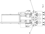
- reference number 1 indicates a pumping apparatus for pumping a food fluid containing solid parts.
- a fluid is typically viscous, e.g., sauces, jams etc.
- the solid parts can reach longitudinal dimensions up to 50 millimetres.
- the apparatus 1 comprises a pumping assembly 2.
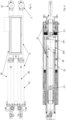
- the pumping assembly 2 in turn comprises a jacket 23 and a piston 24 which is movable alternately backwards and forwards in the jacket 23 in order to pump and suction the fluid.
- the jacket 23 is substantially cylindrical.
- it is made of stainless steel.
- the pumping assembly 2 comprises three lubrication points. All the parts of the pumping assembly 2 in contact with the product are made of FDA certified material.
- the apparatus 1 further comprises an electric motor 3 driving said pumping assembly 2.
- the electric motor 3 is an induction motor with a circular crown stator.
- the electric motor 3 is an asynchronous motor (typically three-phase) or a DC motor or a brushless motor.
- the motor 3 comprises a rotor 31 and a stator 32.
- the stator 32 suitably surrounds at least a part of the rotor 31.
- the stator 32 comprises electrical windings for generating a rotating magnetic field which rotates the rotor 31.
- the electric motor 3 is a commercial motor.
- the electric motor 3 is servo-ventilated.
- the electric motor 3 comprises/is coupled to a frequency converter.
- Such a frequency converter allows the rotation speed of the rotor 31 to be adjusted.
- such a converter allows to adjust the rotation speed of the rotor 31 instant by instant. This allows considerable flexibility of use.
- it allows to control the acceleration and deceleration ramps of the rotor 31 and/or the piston 24.
- the pumping assembly 2 comprises a position control system of the piston 24.
- the position of the piston 24 along the jacket 23 is thus understood. This typically occurs by means of an encoder.
- a control system e.g., the encoder
- the position control system of the piston 24 is operatively associated with the frequency converter.
- the frequency converter is suitably actuated as a function of the position of the piston 24 detected by the control system.
- the speed of the piston 24 can be controlled as the position of the piston varies along the stroke thereof.
- the frequency converter allows the piston to follow specific acceleration and/or deceleration profiles straddling the inversion of the motion of the piston 24 itself.
- the apparatus 1 further comprises means for managing the acceleration ramps of the piston 24. This is done by electronic control of the axes, which prevents water hammers in the downstream circuit.
- the electric motor 3 is therefore capable of controlling the acceleration ramps.
- the apparatus 1 can suitably further comprise a speed adapter 4 operatively interposed between the electric motor 3 and said pumping system 2.
- the speed adapter 4 allows to provide a different angular speed in output relative to the input speed given by the rotor 31 of the electric motor 3.
- the adapter 4 is a mechanical system, typically geared.
- the speed adapter 4 is typically a speed reducer. It therefore allows to provide a power take-off at the output with a lower angular speed relative to that of a rotor of the electric motor 3.
- the reducer can also be integrated/combined in the electric motor 3 so as to define a gear motor.
- said speed adapter 4 (in particular said reducer) has a power output (typically by means of a drive shaft) in a direction orthogonal to that of the input of the rotor 31.
- the pumping assembly 2 comprises a drive shaft 21 actuated by said adapter 4.
- the drive shaft 21 comprises a groove 211 extending spirally. Such a groove 211 extends along at least one section of a radially outermost side surface of the drive shaft 21.
- the pumping assembly 2 comprises a driven actuator 22 which is slidable forwards and backwards.
- the driven actuator 22 is a linear actuator. It suitably translates forwards and backwards moved by the drive shaft 21.
- the driven actuator 22 comprises a recess 221 extending spirally about at least one section of said actuator 22. The recess 221 is at least partially facing the groove 211.
- the pumping assembly 2 comprises a plurality of rolling elements 25 which engage in both said groove 211 and in said recess 221. Such rolling elements 25 are typically spheres. It is thereby possible to transfer the motion from the drive shaft 21 to the driven actuator 22. A rotary motion of said drive shaft 21 may then be transferred into a forward or return stroke of said driven actuator 22.
- the drive shaft 21 with the groove 211, the driven actuator 22 with the recess 221, the rolling means 25 define a ball recirculation system.
- they define a system known in other applications as a recirculating ball screw.
- the driven actuator 22 is constrained to the piston 24. Preferably they are assembled together.
- the piston 24 could be integral with the driven actuator 22.
- the piston 24 and the driven actuator 22 could also be a single monolithic body.
- the driven actuator 22 moves in one direction or the other.
- the rotor 31 is rotatable about a first axis 310 which is orthogonal to a second axis 26 along which said driven actuator 22 and said drive shaft 21 extend.
- the actuator 22 translates along said second axis 26.
- the second axis 26 also identifies a translation direction of the piston 24.
- the driven actuator 22 is typically coaxial with the drive shaft 21.
- the driven actuator 22 surrounds the drive shaft 21.
- the driven actuator 22 preferably surrounds and is positioned externally to said drive shaft 21.
- the driven actuator 22 comprises a cavity in which said drive shaft 21 protrudes. However, there could be an opposite solution in which the drive shaft 21 surrounds at least one section of the driven actuator 22.
- the drive shaft 21 and the driven actuator 22 define a telescopic structure.
- a telescopic structure lengthens or shortens.
- an insertion or extraction of one between the shaft 21 or the actuator 22 relative to the other is caused.
- an extraction of the actuator 22 from the shaft 21 corresponds to a pumping stroke of the piston 24.
- an insertion of the actuator 22 into the shaft 21 corresponds to a suction stroke of the piston 24.
- the stroke of the piston 24 is adjustable by acting on the control of the electric motor 3.
- the maximum stroke of the piston 24 is comprised between 0.7 and 1.2 metres.
- the axial position of the drive shaft 21 is fixed along said second axis 26.
- the actuator 22 moves, in particular translates, along said axis 26.
- the pumping assembly 2 comprises a guiding means which inhibits the rotation of said driven actuator 22 allowing the translation thereof along the second axis 26.
- the pumping system 2 comprises an outer casing 27 which wraps around at least a part of the drive shaft 21 and the driven actuator 22.
- the motor 3 is external to the casing 27.
- the motor 3 is also external to the jacket 23.
- the casing 27 is suitably external, preferably adjacent, to the jacket 23.
- the pumping assembly 2 comprises a pumping chamber 230 positioned in said jacket 23 and in which the fluid is suctioned and pumped by said piston 24.
- the pumping assembly 2 comprises an intake valve 231 which, in an open configuration, permits the entry of said fluid into the pumping chamber 230.
- the pumping assembly 2 comprises a delivery valve 232 which, in an open configuration, permits the pumping of the fluid present in the pumping chamber 230.
- the intake valve 231 and/or the delivery valve 232 is/are ball valves.
- the suction valve 231 and the delivery valve 232 are pneumatically controlled.
- the suction valve 231 and the delivery valve 232 are remotely controlled.
- remotely controlled pneumatic means are present for controlling the valves 231 and 232.
- the valves 231, 232 could be operated in another manner, for example by a solenoid.
- the use of remotely controlled valves is interesting, as it facilitates large passage sections.
- the intake valve 23 if open, has a passage section which is at least 60% (preferably 75%) of the section of the intake duct immediately upstream of the valve 231.
- the delivery valve 232 allows to free a passage section which is at least 60% (preferably 75%) of the section of the delivery duct immediately downstream of the valve 232. This is useful for facilitating the passage of solid parts.
- the jacket 23 can suction axially and pump orthogonally to a movement direction of the cylinder 23. But also vice versa.
- the pumping assembly 2 has reversible operation.
- the driven actuator 22 comprises an annular sleeve 220 which wraps around a section of said drive shaft 21 and in which said rolling elements 25 are contained.
- the jacket 220 extends axially for less than 1/5 of a stroke of the driven actuator 22.
- the pumping apparatus 1 also comprises an additional pumping assembly 20 suitably actuated by an additional electric motor 30.
- This description for the pumping assembly 2, for the electric motor 3 and the reciprocal interactions thereof can be respectively repeated for the additional pumping assembly 20, for the additional electric motor 30 and the reciprocal interactions thereof.
- the additional pumping assembly is a pump provided with a piston which moves alternately along a direction parallel to the second axis 26 described above.
- the pumping assembly 2 and the additional pumping assembly 20 are side by side. The use of two pumping assemblies allows to give greater regularity to the fluid flow rate. In fact, when the pumping assembly 2 is in the suction step, the pumping assembly 20 will be in the pumping step.
- the additional electric motor 30 comprises a frequency converter which allows the rotor speed to be promptly adjusted as a function of a signal provided by a piston position control system of the additional pumping assembly 20.
- the frequency converter of the motor 3 and the frequency converter of the motor 30 are able to control the movement of the piston of the pumping assembly 2 and the piston of the pumping assembly 20 so as to have a compressive fluid flow rate processed by the sum of the pumping assembly 2 and the pumping assembly 20 which is constant over time (regardless of the inversion of the motion of the respective pistons).
- the frequency converter of the motor 3 and the frequency converter of the motor 30 are therefore synchronised.
- An object of the present invention is also a system 10 for treating a food fluid containing solid particles.
- a system 10 comprises a pumping apparatus 1 having one or more of the features described previously.
- the system 10 further comprises a fluid heating means 5 positioned downstream of said delivery valve 232. There is no fluid homogenising valve or narrow gap present between the delivery valve 232 and the heating means 5. More generally, and regardless of the presence of the heating means 5, there is no fluid homogenising valve or narrow gap for crushing the solid parts.
- An object of the present invention is further a pumping method for pumping a food fluid containing solid parts by means of a pumping assembly 2.
- a pumping apparatus 1 and/or a treatment system 10.
- the pumping assembly 2 comprises a jacket 23 and a piston 24 slidable alternately in the jacket 23. Such a piston 24 alternately moves forwards and backwards in the jacket 23. The movement of the piston 24 causes the pumping and/or suction of the fluid with respect to the jacket 23.
- the method comprises the step of actuating a drive shaft 21 of the pumping assembly 2 by means of at least one electric motor 3 and suitably a speed adapter 4.
- the speed adapter 4 rotates the drive shaft 21 at a different angular speed relative to that of a rotor 31 of the motor 3.
- the method further comprises the step of transferring motion from said drive shaft 21 to a driven actuator 22 positioned in said pumping assembly 2 by means of a plurality of rolling elements 25.
- the rolling elements 25 suitably engage:
- the driven actuator 22 is constrained to the piston 24.
- the piston 24 suctions and pumps the fluid.
- the method can optionally comprise the step of pumping the fluid to a heating means 5 of said fluid without passing it through a homogenising valve or narrow gap intended to crush said solid parts.
- the pumping method for pumping a food fluid containing solid parts is implemented by means of at least:
- the pumping assembly 2 and the additional pumping assembly 20 could follow different profiles of the flow rate - time curve.
- the present invention achieves important advantages.
- the solution exemplified in the accompanying figures has a longitudinal length of about 4 metres, a width of about 0.8 metres and a height of less than 0.2 metres; it can allow a flow rate of about 10,000 litres/hour with a pressure of about 6 bar).
Landscapes
- Engineering & Computer Science (AREA)
- Mechanical Engineering (AREA)
- General Engineering & Computer Science (AREA)
- Reciprocating Pumps (AREA)
- Water Treatment By Sorption (AREA)
Claims (9)
- Système pour traiter un liquide alimentaire contenant des parties solides, comprenant :- le liquide alimentaire contenant lesdites parties solides ;- un système de pompage pour liquide alimentaire contenant des parties solides, comprenant à son tour :ledit ensemble de pompage (2) comprenant :i) un ensemble de pompage (2), comprenant une chemise (23) et un piston (24) qui est mobile alternativement dans la chemise (23) afin d'aspirer et de pomper le liquide ;ii) un moteur électrique (3) entraînant ledit ensemble de pompage (2) ;iii) un adaptateur de vitesse (4) interposé de manière opérationnelle entre le moteur électrique (3) et ledit ensemble de pompage (2) ;- un arbre d'entraînement (21) actionné par ledit adaptateur (4) et comprenant une rainure (211) s'étendant en spirale ;- un actionneur entraîné (22) coulissant vers l'avant et vers l'arrière et comprenant un évidement (221) s'étendant en spirale autour d'au moins une section dudit actionneur (22) ;- une pluralité d'éléments roulants (25) qui s'engagent à la fois dans ladite rainure (211) et dans ledit évidement (221) afin de transférer un mouvement rotatif dudit arbre d'entraînement (21) dans une course avant ou arrière dudit actionneur entraîné (22) ; ledit actionneur entraîné (22) étant contraint audit piston (24) ;- une chambre de pompage (230) positionnée dans ladite chemise (23) et dans laquelle le liquide est aspiré et pompé par ledit piston (24) ;- une soupape d'admission qui, dans une configuration ouverte, permet l'entrée dudit liquide dans la chambre de pompage (230) et une soupape de refoulement qui, dans une configuration ouverte, permet le pompage du liquide présent dans la chambre de pompage (230) ; caractérisé en ce que la soupape d'admission et la soupape de refoulement sont actionnées par un actionneur commandé à distance.
- Système selon la revendication 1, caractérisé en ce que ledit moteur électrique (3) comprend un rotor (31) pouvant tourner autour d'un premier axe (310) qui est orthogonal à un second axe (26) le long duquel ledit arbre d'entraînement (21) peut tourner.
- Système selon la revendication 2, caractérisé en ce que la position axiale dudit arbre d'entraînement (21) est fixe le long dudit deuxième axe (26).
- Système selon l'une quelconque des revendications précédentes, caractérisé en ce que ledit actionneur entraîné (22) est coaxial avec, entoure et est positionné à l'extérieur dudit arbre d'entraînement (21).
- Système selon l'une quelconque des revendications précédentes, caractérisé en ce que ledit ensemble de pompage (2) comprend un carter extérieur (27) qui entoure au moins une partie de l'arbre d'entraînement (21) et de l'actionneur entraîné (22) ; ledit moteur (3) étant externe audit carter (27).
- Système selon l'une quelconque des revendications précédentes, caractérisé en ce que ledit actionneur entraîné (22) comprend un manchon annulaire (220) qui s'enroule autour d'une section dudit arbre d'entraînement (21) et dans lequel lesdits éléments roulants (25) sont contenus ; ledit manchon (220) s'étendant axialement sur moins de 1/5 d'une course de l'actionneur entraîné (22).
- Système selon l'une quelconque des revendications précédentes comprend des moyens de chauffage (5) pour chauffer le liquide, positionnés en aval dudit système de pompage (1) ; aucune vanne d'homogénéisation ou rétrécissement pour homogénéiser le liquide n'étant présent entre ledit système de pompage (1) et lesdits moyens de chauffage (5).
- Système selon l'une quelconque des revendications précédentes, caractérisé en ce que la soupape d'admission, si elle est ouverte, a une section de passage qui est au moins 60% de la section d'un conduit d'admission immédiatement en amont de la soupape d'admission ; la soupape de refoulement permettant de libérer une section de passage qui est au moins 60% de la section du conduit de refoulement immédiatement en aval de la soupape de refoulement.
- Système selon l'une quelconque des revendications précédentes, caractérisé en ce que le moteur électrique (3) comprend/est couplé à un convertisseur de fréquence ; le système de pompage (1) comprend également un ensemble de pompage supplémentaire (20) actionné par un moteur électrique supplémentaire (30) ; le moteur électrique supplémentaire (30) comprenant un convertisseur de fréquence qui permet d'ajuster rapidement la vitesse du rotor en fonction d'un signal fourni par un système de commande de position de piston de l'ensemble de pompage supplémentaire (20) ;
le convertisseur de fréquence du moteur (3) et le convertisseur de fréquence du moteur (30) sont capables de commander le mouvement du piston de l'ensemble de pompage (2) et du piston de l'ensemble de pompage (20) de manière à avoir un débit de liquide de compression traité par la somme de l'ensemble de pompage (2) et de l'ensemble de pompage supplémentaire (20) qui est constant dans le temps indépendamment de l'inversion du mouvement des pistons respectifs.
Applications Claiming Priority (2)
| Application Number | Priority Date | Filing Date | Title |
|---|---|---|---|
| IT102020000007915A IT202000007915A1 (it) | 2020-04-15 | 2020-04-15 | Sistema di pompaggio di fluidi contenenti particelle solide |
| PCT/IB2021/053037 WO2021209894A1 (fr) | 2020-04-15 | 2021-04-13 | Appareil de pompage de fluides contenant des particules solides |
Publications (3)
| Publication Number | Publication Date |
|---|---|
| EP4136352A1 EP4136352A1 (fr) | 2023-02-22 |
| EP4136352C0 EP4136352C0 (fr) | 2024-11-27 |
| EP4136352B1 true EP4136352B1 (fr) | 2024-11-27 |
Family
ID=71170779
Family Applications (1)
| Application Number | Title | Priority Date | Filing Date |
|---|---|---|---|
| EP21723375.8A Active EP4136352B1 (fr) | 2020-04-15 | 2021-04-13 | Système de pompage pour liquides contenant des particules solides |
Country Status (3)
| Country | Link |
|---|---|
| EP (1) | EP4136352B1 (fr) |
| IT (1) | IT202000007915A1 (fr) |
| WO (1) | WO2021209894A1 (fr) |
Citations (3)
| Publication number | Priority date | Publication date | Assignee | Title |
|---|---|---|---|---|
| DE2755233A1 (de) * | 1977-12-10 | 1979-06-13 | Bruss Foerdertechnik Kg | Einrichtung zur foerderung und dosierung von nassem, pumpfaehigen tierfutter |
| DE4300512B4 (de) * | 1993-01-12 | 2007-05-24 | Bayerische Motoren Werke Ag | Antrieb für eine Kraftstoffpumpe von Fahrzeugen |
| EP3023638B1 (fr) * | 2014-11-17 | 2020-01-22 | Tecnogomma S.R.L. | Unité de pompage de liquides alimentaires |
Family Cites Families (4)
| Publication number | Priority date | Publication date | Assignee | Title |
|---|---|---|---|---|
| US4938543A (en) * | 1989-05-17 | 1990-07-03 | General Motors Corporation | Anti-lock braking/traction control braking system |
| US6079797A (en) * | 1996-08-16 | 2000-06-27 | Kelsey-Hayes Company | Dual action ball screw pump |
| US6068448A (en) * | 1996-12-09 | 2000-05-30 | Sugino Machine Limited | Pressure hydraulic pump having first and second synchronously driven reciprocating pistons with a pressure control structure |
| DE102015223507A1 (de) * | 2015-11-27 | 2017-06-01 | Robert Bosch Gmbh | Kolbenpumpenaggregat |
-
2020
- 2020-04-15 IT IT102020000007915A patent/IT202000007915A1/it unknown
-
2021
- 2021-04-13 WO PCT/IB2021/053037 patent/WO2021209894A1/fr not_active Ceased
- 2021-04-13 EP EP21723375.8A patent/EP4136352B1/fr active Active
Patent Citations (3)
| Publication number | Priority date | Publication date | Assignee | Title |
|---|---|---|---|---|
| DE2755233A1 (de) * | 1977-12-10 | 1979-06-13 | Bruss Foerdertechnik Kg | Einrichtung zur foerderung und dosierung von nassem, pumpfaehigen tierfutter |
| DE4300512B4 (de) * | 1993-01-12 | 2007-05-24 | Bayerische Motoren Werke Ag | Antrieb für eine Kraftstoffpumpe von Fahrzeugen |
| EP3023638B1 (fr) * | 2014-11-17 | 2020-01-22 | Tecnogomma S.R.L. | Unité de pompage de liquides alimentaires |
Also Published As
| Publication number | Publication date |
|---|---|
| EP4136352C0 (fr) | 2024-11-27 |
| EP4136352A1 (fr) | 2023-02-22 |
| WO2021209894A1 (fr) | 2021-10-21 |
| IT202000007915A1 (it) | 2021-10-15 |
Similar Documents
| Publication | Publication Date | Title |
|---|---|---|
| EP2753832B1 (fr) | Système de pompe et procede de fonctionnement d'une pompe | |
| CN104884798B (zh) | 高压均质机 | |
| JP2011515616A (ja) | 交互の回転を直線的変位に変換する駆動機構を備えた超高圧ポンプ | |
| US20200362838A1 (en) | Electric linear-actuator pumping system | |
| CA2143161A1 (fr) | Pompe particulierement utile dans des appareils respiratoires | |
| US8696324B2 (en) | Quintuplex mud pump | |
| EP3023638B1 (fr) | Unité de pompage de liquides alimentaires | |
| CN103557148B (zh) | 一种通过频率控制柱塞泵方法及柱塞泵 | |
| CN115667716A (zh) | 具有高扭矩驱动器的泵 | |
| CN216008789U (zh) | 单级柱塞泵及应用其的计量泵 | |
| US4604539A (en) | Drive mechanism with a rotary drive motor | |
| EP4136352A1 (fr) | Appareil de pompage de fluides contenant des particules solides | |
| US11454226B2 (en) | Electric off-axis opposing piston linear actuator pumping system | |
| EP2083171A1 (fr) | Appareil de manipulation de fluide | |
| US11635071B2 (en) | Co-axial inverted piston linear actuator pumping system | |
| WO2020026135A1 (fr) | Homogénéisateur haute pression | |
| US11396868B2 (en) | Linear actuator pumping system | |
| US20250290494A1 (en) | Oscillating metering pump | |
| CN111135739A (zh) | 粉液混合泵的防堵料方法 | |
| EP4368834A1 (fr) | Actionneur linéaire pour pompe à haute pression | |
| KR200228703Y1 (ko) | 다이아프램 펌프 | |
| CA3099133C (fr) | Homogeneisateur haute pression | |
| CN113653628B (zh) | 加注泵 | |
| CN213655052U (zh) | 一种长行程大推力的动力端 | |
| CN109952432A (zh) | 容积泵 |
Legal Events
| Date | Code | Title | Description |
|---|---|---|---|
| STAA | Information on the status of an ep patent application or granted ep patent |
Free format text: STATUS: UNKNOWN |
|
| STAA | Information on the status of an ep patent application or granted ep patent |
Free format text: STATUS: THE INTERNATIONAL PUBLICATION HAS BEEN MADE |
|
| PUAI | Public reference made under article 153(3) epc to a published international application that has entered the european phase |
Free format text: ORIGINAL CODE: 0009012 |
|
| STAA | Information on the status of an ep patent application or granted ep patent |
Free format text: STATUS: REQUEST FOR EXAMINATION WAS MADE |
|
| 17P | Request for examination filed |
Effective date: 20220928 |
|
| AK | Designated contracting states |
Kind code of ref document: A1 Designated state(s): AL AT BE BG CH CY CZ DE DK EE ES FI FR GB GR HR HU IE IS IT LI LT LU LV MC MK MT NL NO PL PT RO RS SE SI SK SM TR |
|
| P01 | Opt-out of the competence of the unified patent court (upc) registered |
Effective date: 20230526 |
|
| DAV | Request for validation of the european patent (deleted) | ||
| DAX | Request for extension of the european patent (deleted) | ||
| GRAP | Despatch of communication of intention to grant a patent |
Free format text: ORIGINAL CODE: EPIDOSNIGR1 |
|
| STAA | Information on the status of an ep patent application or granted ep patent |
Free format text: STATUS: GRANT OF PATENT IS INTENDED |
|
| INTG | Intention to grant announced |
Effective date: 20240702 |
|
| GRAS | Grant fee paid |
Free format text: ORIGINAL CODE: EPIDOSNIGR3 |
|
| GRAA | (expected) grant |
Free format text: ORIGINAL CODE: 0009210 |
|
| STAA | Information on the status of an ep patent application or granted ep patent |
Free format text: STATUS: THE PATENT HAS BEEN GRANTED |
|
| AK | Designated contracting states |
Kind code of ref document: B1 Designated state(s): AL AT BE BG CH CY CZ DE DK EE ES FI FR GB GR HR HU IE IS IT LI LT LU LV MC MK MT NL NO PL PT RO RS SE SI SK SM TR |
|
| REG | Reference to a national code |
Ref country code: GB Ref legal event code: FG4D |
|
| REG | Reference to a national code |
Ref country code: CH Ref legal event code: EP |
|
| REG | Reference to a national code |
Ref country code: DE Ref legal event code: R096 Ref document number: 602021022436 Country of ref document: DE |
|
| REG | Reference to a national code |
Ref country code: IE Ref legal event code: FG4D |
|
| U01 | Request for unitary effect filed |
Effective date: 20241202 |
|
| P04 | Withdrawal of opt-out of the competence of the unified patent court (upc) registered |
Free format text: CASE NUMBER: APP_65076/2024 Effective date: 20241209 |
|
| U07 | Unitary effect registered |
Designated state(s): AT BE BG DE DK EE FI FR IT LT LU LV MT NL PT RO SE SI Effective date: 20241211 |
|
| PG25 | Lapsed in a contracting state [announced via postgrant information from national office to epo] |
Ref country code: HR Free format text: LAPSE BECAUSE OF FAILURE TO SUBMIT A TRANSLATION OF THE DESCRIPTION OR TO PAY THE FEE WITHIN THE PRESCRIBED TIME-LIMIT Effective date: 20241127 Ref country code: IS Free format text: LAPSE BECAUSE OF FAILURE TO SUBMIT A TRANSLATION OF THE DESCRIPTION OR TO PAY THE FEE WITHIN THE PRESCRIBED TIME-LIMIT Effective date: 20250327 |
|
| PG25 | Lapsed in a contracting state [announced via postgrant information from national office to epo] |
Ref country code: ES Free format text: LAPSE BECAUSE OF FAILURE TO SUBMIT A TRANSLATION OF THE DESCRIPTION OR TO PAY THE FEE WITHIN THE PRESCRIBED TIME-LIMIT Effective date: 20241127 |
|
| PG25 | Lapsed in a contracting state [announced via postgrant information from national office to epo] |
Ref country code: NO Free format text: LAPSE BECAUSE OF FAILURE TO SUBMIT A TRANSLATION OF THE DESCRIPTION OR TO PAY THE FEE WITHIN THE PRESCRIBED TIME-LIMIT Effective date: 20250227 |
|
| PG25 | Lapsed in a contracting state [announced via postgrant information from national office to epo] |
Ref country code: GR Free format text: LAPSE BECAUSE OF FAILURE TO SUBMIT A TRANSLATION OF THE DESCRIPTION OR TO PAY THE FEE WITHIN THE PRESCRIBED TIME-LIMIT Effective date: 20250228 |
|
| PG25 | Lapsed in a contracting state [announced via postgrant information from national office to epo] |
Ref country code: PL Free format text: LAPSE BECAUSE OF FAILURE TO SUBMIT A TRANSLATION OF THE DESCRIPTION OR TO PAY THE FEE WITHIN THE PRESCRIBED TIME-LIMIT Effective date: 20241127 |
|
| PG25 | Lapsed in a contracting state [announced via postgrant information from national office to epo] |
Ref country code: RS Free format text: LAPSE BECAUSE OF FAILURE TO SUBMIT A TRANSLATION OF THE DESCRIPTION OR TO PAY THE FEE WITHIN THE PRESCRIBED TIME-LIMIT Effective date: 20250227 |
|
| U20 | Renewal fee for the european patent with unitary effect paid |
Year of fee payment: 5 Effective date: 20250429 |
|
| PG25 | Lapsed in a contracting state [announced via postgrant information from national office to epo] |
Ref country code: SM Free format text: LAPSE BECAUSE OF FAILURE TO SUBMIT A TRANSLATION OF THE DESCRIPTION OR TO PAY THE FEE WITHIN THE PRESCRIBED TIME-LIMIT Effective date: 20241127 |
|
| PG25 | Lapsed in a contracting state [announced via postgrant information from national office to epo] |
Ref country code: SK Free format text: LAPSE BECAUSE OF FAILURE TO SUBMIT A TRANSLATION OF THE DESCRIPTION OR TO PAY THE FEE WITHIN THE PRESCRIBED TIME-LIMIT Effective date: 20241127 |
|
| PG25 | Lapsed in a contracting state [announced via postgrant information from national office to epo] |
Ref country code: CZ Free format text: LAPSE BECAUSE OF FAILURE TO SUBMIT A TRANSLATION OF THE DESCRIPTION OR TO PAY THE FEE WITHIN THE PRESCRIBED TIME-LIMIT Effective date: 20241127 |
|
| PLBE | No opposition filed within time limit |
Free format text: ORIGINAL CODE: 0009261 |
|
| STAA | Information on the status of an ep patent application or granted ep patent |
Free format text: STATUS: NO OPPOSITION FILED WITHIN TIME LIMIT |
|
| REG | Reference to a national code |
Ref country code: CH Ref legal event code: L10 Free format text: ST27 STATUS EVENT CODE: U-0-0-L10-L00 (AS PROVIDED BY THE NATIONAL OFFICE) Effective date: 20251008 |
|
| 26N | No opposition filed |
Effective date: 20250828 |
|
| REG | Reference to a national code |
Ref country code: CH Ref legal event code: H13 Free format text: ST27 STATUS EVENT CODE: U-0-0-H10-H13 (AS PROVIDED BY THE NATIONAL OFFICE) Effective date: 20251125 |
|
| PG25 | Lapsed in a contracting state [announced via postgrant information from national office to epo] |
Ref country code: MC Free format text: LAPSE BECAUSE OF FAILURE TO SUBMIT A TRANSLATION OF THE DESCRIPTION OR TO PAY THE FEE WITHIN THE PRESCRIBED TIME-LIMIT Effective date: 20241127 |
|
| GBPC | Gb: european patent ceased through non-payment of renewal fee |
Effective date: 20250413 |
|
| PG25 | Lapsed in a contracting state [announced via postgrant information from national office to epo] |
Ref country code: GB Free format text: LAPSE BECAUSE OF NON-PAYMENT OF DUE FEES Effective date: 20250413 |
|
| PG25 | Lapsed in a contracting state [announced via postgrant information from national office to epo] |
Ref country code: CH Free format text: LAPSE BECAUSE OF NON-PAYMENT OF DUE FEES Effective date: 20250430 |
|
| PG25 | Lapsed in a contracting state [announced via postgrant information from national office to epo] |
Ref country code: IE Free format text: LAPSE BECAUSE OF NON-PAYMENT OF DUE FEES Effective date: 20250413 |