EP4135889B1 - Station de polymerisation pour greffage d'un revetement bioactif - Google Patents
Station de polymerisation pour greffage d'un revetement bioactif Download PDFInfo
- Publication number
- EP4135889B1 EP4135889B1 EP21726152.8A EP21726152A EP4135889B1 EP 4135889 B1 EP4135889 B1 EP 4135889B1 EP 21726152 A EP21726152 A EP 21726152A EP 4135889 B1 EP4135889 B1 EP 4135889B1
- Authority
- EP
- European Patent Office
- Prior art keywords
- reactor
- tank
- grafting
- monomer solution
- vessel
- Prior art date
- Legal status (The legal status is an assumption and is not a legal conclusion. Google has not performed a legal analysis and makes no representation as to the accuracy of the status listed.)
- Active
Links
Images
Classifications
-
- B—PERFORMING OPERATIONS; TRANSPORTING
- B01—PHYSICAL OR CHEMICAL PROCESSES OR APPARATUS IN GENERAL
- B01J—CHEMICAL OR PHYSICAL PROCESSES, e.g. CATALYSIS OR COLLOID CHEMISTRY; THEIR RELEVANT APPARATUS
- B01J19/00—Chemical, physical or physico-chemical processes in general; Their relevant apparatus
- B01J19/18—Stationary reactors having moving elements inside
- B01J19/1862—Stationary reactors having moving elements inside placed in series
-
- B—PERFORMING OPERATIONS; TRANSPORTING
- B01—PHYSICAL OR CHEMICAL PROCESSES OR APPARATUS IN GENERAL
- B01J—CHEMICAL OR PHYSICAL PROCESSES, e.g. CATALYSIS OR COLLOID CHEMISTRY; THEIR RELEVANT APPARATUS
- B01J19/00—Chemical, physical or physico-chemical processes in general; Their relevant apparatus
- B01J19/0006—Controlling or regulating processes
- B01J19/004—Multifunctional apparatus for automatic manufacturing of various chemical products
-
- C—CHEMISTRY; METALLURGY
- C08—ORGANIC MACROMOLECULAR COMPOUNDS; THEIR PREPARATION OR CHEMICAL WORKING-UP; COMPOSITIONS BASED THEREON
- C08L—COMPOSITIONS OF MACROMOLECULAR COMPOUNDS
- C08L51/00—Compositions of graft polymers in which the grafted component is obtained by reactions only involving carbon-to-carbon unsaturated bonds; Compositions of derivatives of such polymers
- C08L51/003—Compositions of graft polymers in which the grafted component is obtained by reactions only involving carbon-to-carbon unsaturated bonds; Compositions of derivatives of such polymers grafted on to macromolecular compounds obtained by reactions only involving unsaturated carbon-to-carbon bonds
-
- C—CHEMISTRY; METALLURGY
- C08—ORGANIC MACROMOLECULAR COMPOUNDS; THEIR PREPARATION OR CHEMICAL WORKING-UP; COMPOSITIONS BASED THEREON
- C08L—COMPOSITIONS OF MACROMOLECULAR COMPOUNDS
- C08L51/00—Compositions of graft polymers in which the grafted component is obtained by reactions only involving carbon-to-carbon unsaturated bonds; Compositions of derivatives of such polymers
- C08L51/10—Compositions of graft polymers in which the grafted component is obtained by reactions only involving carbon-to-carbon unsaturated bonds; Compositions of derivatives of such polymers grafted on to inorganic materials
-
- D—TEXTILES; PAPER
- D06—TREATMENT OF TEXTILES OR THE LIKE; LAUNDERING; FLEXIBLE MATERIALS NOT OTHERWISE PROVIDED FOR
- D06M—TREATMENT, NOT PROVIDED FOR ELSEWHERE IN CLASS D06, OF FIBRES, THREADS, YARNS, FABRICS, FEATHERS OR FIBROUS GOODS MADE FROM SUCH MATERIALS
- D06M14/00—Graft polymerisation of monomers containing carbon-to-carbon unsaturated bonds on to fibres, threads, yarns, fabrics, or fibrous goods made from such materials
- D06M14/08—Graft polymerisation of monomers containing carbon-to-carbon unsaturated bonds on to fibres, threads, yarns, fabrics, or fibrous goods made from such materials on to materials of synthetic origin
- D06M14/12—Graft polymerisation of monomers containing carbon-to-carbon unsaturated bonds on to fibres, threads, yarns, fabrics, or fibrous goods made from such materials on to materials of synthetic origin of macromolecular compounds obtained otherwise than by reactions only involving carbon-to-carbon unsaturated bonds
- D06M14/14—Polyesters
-
- B—PERFORMING OPERATIONS; TRANSPORTING
- B01—PHYSICAL OR CHEMICAL PROCESSES OR APPARATUS IN GENERAL
- B01J—CHEMICAL OR PHYSICAL PROCESSES, e.g. CATALYSIS OR COLLOID CHEMISTRY; THEIR RELEVANT APPARATUS
- B01J2219/00—Chemical, physical or physico-chemical processes in general; Their relevant apparatus
- B01J2219/00049—Controlling or regulating processes
- B01J2219/00051—Controlling the temperature
- B01J2219/00074—Controlling the temperature by indirect heating or cooling employing heat exchange fluids
- B01J2219/00087—Controlling the temperature by indirect heating or cooling employing heat exchange fluids with heat exchange elements outside the reactor
- B01J2219/00094—Jackets
-
- D—TEXTILES; PAPER
- D06—TREATMENT OF TEXTILES OR THE LIKE; LAUNDERING; FLEXIBLE MATERIALS NOT OTHERWISE PROVIDED FOR
- D06M—TREATMENT, NOT PROVIDED FOR ELSEWHERE IN CLASS D06, OF FIBRES, THREADS, YARNS, FABRICS, FEATHERS OR FIBROUS GOODS MADE FROM SUCH MATERIALS
- D06M2101/00—Chemical constitution of the fibres, threads, yarns, fabrics or fibrous goods made from such materials, to be treated
- D06M2101/16—Synthetic fibres, other than mineral fibres
- D06M2101/30—Synthetic polymers consisting of macromolecular compounds obtained otherwise than by reactions only involving carbon-to-carbon unsaturated bonds
- D06M2101/32—Polyesters
-
- D—TEXTILES; PAPER
- D10—INDEXING SCHEME ASSOCIATED WITH SUBLASSES OF SECTION D, RELATING TO TEXTILES
- D10B—INDEXING SCHEME ASSOCIATED WITH SUBLASSES OF SECTION D, RELATING TO TEXTILES
- D10B2331/00—Fibres made from polymers obtained otherwise than by reactions only involving carbon-to-carbon unsaturated bonds, e.g. polycondensation products
- D10B2331/04—Fibres made from polymers obtained otherwise than by reactions only involving carbon-to-carbon unsaturated bonds, e.g. polycondensation products polyesters, e.g. polyethylene terephthalate [PET]
- D10B2331/041—Fibres made from polymers obtained otherwise than by reactions only involving carbon-to-carbon unsaturated bonds, e.g. polycondensation products polyesters, e.g. polyethylene terephthalate [PET] derived from hydroxy-carboxylic acids, e.g. lactones
Definitions
- the present invention relates to a polymerization station and a method for grafting a bioactive polymer, such as PolyNaSS, onto an article, in particular polymer or ceramic.
- the polymerization station comprises a reactor comprising a tank intended to accommodate the articles with a view to their oxidation and grafting, a cover mounted in a sealed manner on the tank, an inlet for at least partially filling the tank in order to immerse the articles and an drain outlet to empty the tank.
- This type of reactor is known from the prior art, in particular for carrying out experiments, such as synthesis, in the laboratory on a small and medium scale.
- the aim of the invention is to carry out oxidation and grafting on an industrial scale, that is to say in a repeatable and guaranteed manner in large mass and at a rapid rate, which is not the case in the laboratory.
- US2005/229323 describes a process using reactors in a polymerization station to graft a bioactive polymer.
- the invention proposes an oxidation and grafting process for grafting a bioactive polymer, such as PolyNaSS, onto an article, in particular polymer or ceramic, the process comprising an oxidation step by ozonation and a step of grafting by radical polymerization in a polymerization station comprising a first reactor, the process being characterized in that the two stages of oxidation and grafting are carried out consecutively in different solutions in the reactor of the polymerization station.
- a bioactive polymer such as PolyNaSS
- the first reactor comprises a first tank intended to accommodate the articles with a view to their oxidation and grafting, a first cover mounted in a sealed manner on the first tank, an inlet for filling at least partially the first tank in order to immerse the articles, a first drain outlet for draining the first tank, an ozone inlet to create a bubbling of ozone in the first tank in order to oxidize the surface of the articles immersed in the water, and a monomer solution inlet to fill at least partially the first tank in monomer solution, in order to immerse the articles in the monomer solution.
- the grafting step by polymerization comprises the preparation of an aqueous solution of monomer in a second reactor of the polymerization station connected in series upstream of the first reactor, in order to be able to transfer the monomer solution from the second reactor into the first reactor.
- the two reactors can be maintained at overpressure by injecting an inert gas, such as argon.
- the ozonation oxidation step comprises filling at least partially the first reactor with water coming from the second reactor.
- the first tank comprises a first double wall so as to define a peripheral circuit for the circulation of a heat transfer fluid, such as oil, with the aim of heating the contents of the first tank to a predetermined temperature.
- the second reactor may comprise a second tank intended to be filled at least partially with a monomer solution, a second cover mounted in a sealed manner on the second tank, a second drain outlet connected to the inlet of monomer solution from the first reactor to drain the monomer solution from the second reactor into the first reactor.
- the second tank can comprise a second double wall so as to define a peripheral circuit for the circulation of a heat transfer fluid, such as oil, with the aim of heating the monomer solution of the second tank to a temperature predetermined.
- the spirit of the invention lies in the fact that the oxidation and grafting steps are carried out in the same reactor.
- the use of a second reactor specially dedicated to the preparation of the monomer solution makes it possible to sequence in time the two stages of oxidation and grafting, namely first oxidation by ozonation, then grafting by polymerization.
- the preparation of the monomer solution in the second reactor also makes it possible to reduce the total duration of the treatment, being since the monomer solution can be prepared and heated to the appropriate temperature during the oxidation step.
- the monomer solution is brought into the first reactor under optimal “ready-to-use” conditions.
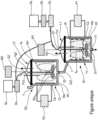
- the single Figure is a schematic view representing an industrial polymerization station of the invention.
- This station includes two reactors R1 and R2 which may be identical or similar, but whose use is different.
- the first reactor R1 comprises a first tank T1 intended to accommodate the articles for their oxidation and grafting.
- the articles are preferably polymeric or ceramic: it may for example be a non-woven textile material made of polymer fibers, such as PCL polycaprolactone. It may also be a ceramic substrate, which may comprise or consist of tricalcium phosphate, and more particularly ⁇ -tricalcium phosphate ( ⁇ -TCP). These are only non-limiting examples.
- the first tank T1 includes an inlet I to fill it at least partially with water or a solution of Sm monomer in order to immerse the articles.
- the first tank T1 also includes a first drain outlet (V1) for emptying it of its contents, namely ozonated water or used monomer solution, as will be seen below.
- the first tank T1 comprises a first double wall Wi, We, so as to define a peripheral circuit Cp for the circulation of a heat transfer fluid, such as oil, with the aim of heating the contents of the first tank T1 to a predetermined temperature.
- the heat transfer fluid is circulated by means of a first external pump P1 and raised to temperature by heating means not shown.
- the first tank T1 contains an agitator S1 which is actuated by an external motor M1.
- the purpose of the agitator S1 is to mix the contents of the first tank T1.
- the first reactor R1 also comprises a first cover L1 mounted in a sealed manner on the first tank T1.
- the cover L1 is removable to access the interior of the first tank T1, in order to be able to place the articles to be grafted there and recover them, once the grafting has been carried out.
- the first cover L1 is provided with an ozone inlet To to create a bubbling of ozone in the first tank T1 with the aim of oxidizing the surface of the articles immersed in water.
- the ozone inlet To is in the form of a tube which passes through the first cover L1 at a joint S1 and extends towards the bottom of the first tank T1. Thus, this tube makes it possible to inject ozone into the first tank T1, when it is filled (partially or totally) with water.
- the tube is connected by a pipe to an ozonator Oz, itself connected to a source of dioxygen So via a flow meter Do.
- the first cover L1 is also equipped with a first thermometer Th1 and a first gas valve Vg.
- the ozone input To can also be connected to a source of inert gas Sa (argon for example) by a flow meter Da.
- the cover L1 can also allow the introduction of pipes connected to a device for continuously measuring the ozone level of the tank T1.
- the second reactor R2 comprises a second tank T2 which includes an inlet Im to fill it at least partially either with water and monomer powder to create a solution of monomer Sm, or with a solution of monomer Sm.
- the second tank T2 also includes a second drain outlet V2 to empty it of its contents, namely the monomer solution ready for use, as will be seen below.
- the second tank T2 comprises a second double wall Wi, We, so as to define a peripheral circuit Cp for the circulation of a heat transfer fluid, such as oil, with the aim of heating the contents of the second tank T2 to a predetermined temperature.
- the heat transfer fluid is circulated by means of a second external pump P2 and raised to temperature by heating means not shown.
- the second tank T2 contains a second agitator S2 which is actuated by a second external motor M2.
- the purpose of the second agitator S2 is to dissolve the monomer powder in the water in the second tank T2 homogeneously.
- the second reactor R2 also comprises a second cover L2 mounted in a sealed manner on the second tank T2.
- the second cover L2 is preferably removable to access the interior of the second tank T2.
- the second cover L2 is provided with an inert gas inlet Ta.
- the inlet Ta is in the form of a tube which passes through the second cover L2 at a joint S2 and advantageously extends towards the bottom of the second tank T2.
- this tube Ta makes it possible to inject an inert gas, such as argon into the second tank T2, when it is filled (partially or totally) with Sm monomer solution.
- the tube is connected by a pipe to the source of inert gas Sa (argon for example) via the flow meter Da. It can be noted that the inert gas source Sa and the flow meter Da can be common to the two reactors R1 and R2.
- the second drain outlet V2 of the second reactor R2 is connected in series to the inlet I of the first reactor R1 by a conduit D21, so that the contents (monomer solution Sm) of the second tank T2 can be dumped or transferred into the first tank T1.
- the Sm monomer solution prepared and heated in the second reactor R2 can fill the first tank T1, where it can be maintained at the same temperature, left to cool or even heated.
- the transfer of the Sm monomer solution is preferably done after draining the ozonated water from the first tank T1.
- the surface of the articles is first oxidized by ozonation, then subsequently coated with bioactive polymer, such as PolyNaSS, by radical grafting. Consequently, the articles are first immersed in water which will be ozonated by bubbling ozone to carry out the surface oxidation, then then immersed in the solution of monomer Sm coming from the second reactor R2 to carry out the grafting by radical polymerization.
- the articles are therefore consecutively oxidized and grafted into one and same reactor, namely the first reactor R1: the second reactor R2 serving only to prepare the Sm monomer solution by mixing and heating to be transferred in a “ready for use” state in the first tank T1.
- the duration of the treatment is considerably reduced, since the oxidation step and the step of preparing the Sm monomer solution can be carried out simultaneously and it is the Sm solution which is transferred to the contact of the articles and not the other way around.
- first reactor R1 and advantageously also the second reactor R2, at slight overpressure, by injecting an inert gas, such as argon, by means of the source Sa and the tubes To and Ta .
- an inert gas such as argon
- water can be introduced into the first reactor R1 by any means and preferably by the inlet I which receives the water from the second reactor R2.
- the durations and temperatures of the oxidation operations, preparation of the Sm monomer solution and grafting depend on the article to be treated and the desired grafting rate.
- the temperature of the Sm monomer solution in the second reactor R2 can be of the order of 40 to 80°C and the temperature of the ozonated water in the first reactor R1 can be of the order of 20 at 40°C.
- articles can be industrially oxidized and grafted in a single reactor R1.
- the duration of the treatment can be reduced, while still controlling it perfectly, by preparing the monomer solution Sm in a second dedicated reactor R2 mounted upstream of the first reactor R1.
Landscapes
- Chemical & Material Sciences (AREA)
- Chemical Kinetics & Catalysis (AREA)
- Organic Chemistry (AREA)
- Engineering & Computer Science (AREA)
- Health & Medical Sciences (AREA)
- Medicinal Chemistry (AREA)
- Polymers & Plastics (AREA)
- Textile Engineering (AREA)
- Inorganic Chemistry (AREA)
- Manufacturing & Machinery (AREA)
- Physical Or Chemical Processes And Apparatus (AREA)
- Graft Or Block Polymers (AREA)
Description
- La présente invention concerne une station de polymérisation et un procédé pour greffer un polymère bioactif, tel que du PolyNaSS, sur un article, notamment polymérique ou céramique. La station de polymérisation comprend un réacteur comprenant une cuve destinée à accueillir les articles en vue de leur oxydation et greffage, un couvercle monté de manière étanche sur la cuve, une entrée pour remplir au moins partiellement la cuve afin d'immerger les articles et une sortie d'évacuation pour vidanger la cuve.
- Ce type de réacteur est connu de l'art antérieur, notamment pour réaliser des expériences, type synthèse, en laboratoire à petite et moyenne échelle.
- Le but de l'invention est de réaliser l'oxydation et le greffage à échelle industrielle, c'est-à-dire de manière répétable et garantie en grande masse et à cadence rapide, ce qui n'est pas le cas en laboratoire.
US2005/229323 décrit un procédé utilisant des réacteurs dans une station de polymérisation pour greffer un polymère bioactif. - Pour ce faire, l'invention propose un procédé d'oxydation et de greffage pour greffer un polymère bioactif, tel que du PolyNaSS, sur un article, notamment polymérique ou céramique, le procédé comprenant une étape d'oxydation par ozonation et une étape de greffage par polymérisation radicalaire dans une station de polymérisation comprenant un premier réacteur, le procédé étant caractérisé en ce que les deux étapes d'oxydation et de greffage sont réalisées de manière consécutive dans des solutions différentes dans le réacteur de la station de polymérisation.
- Selon un mode de réalisation de l'invention, le premier réacteur comprend une première cuve destinée à accueillir les articles en vue de leur oxydation et greffage, un premier couvercle monté de manière étanche sur la première cuve, une entrée pour remplir au moins partiellement la première cuve afin d'immerger les articles, une première sortie de vidange pour vidanger la première cuve, une entrée d'ozone pour créer un bullage d'ozone dans la première cuve dans le but d'oxyder la surface des articles immergés dans l'eau, et une entrée de solution de monomère pour remplir au moins partiellement la première cuve en solution de monomère, afin d'immerger les articles dans la solution de monomère.
- Selon une caractéristique très intéressante de l'invention, l'étape de greffage par polymérisation comprend la préparation d'une solution aqueuse de monomère dans un second réacteur de la station de polymérisation raccordé en série en amont du premier réacteur, afin de pouvoir transvaser la solution de monomère du second réacteur dans le premier réacteur. Les deux réacteurs peuvent être maintenus en surpression par injection d'un gaz inerte, tel que de l'argon. Avantageusement, l'étape d'oxydation par ozonation comprend de remplir au moins partiellement le premier réacteur avec de l'eau en provenance du second réacteur. De préférence, la première cuve comprend une première double paroi de manière à définir un circuit périphérique pour la circulation d'un fluide caloporteur, tel que de l'huile, dans le but de chauffer le contenu de la première cuve à une température prédéterminée.
- Selon un mode de réalisation pratique, le second réacteur peut comprendre une seconde cuve destinée à être remplie au moins partiellement avec une solution de monomère, un second couvercle monté de manière étanche sur la seconde cuve, une seconde sortie de vidange reliée à l'entrée de solution de monomère du premier réacteur pour vidanger la solution de monomère du second réacteur dans le premier réacteur. Avantageusement, la seconde cuve peut comprendre une seconde double paroi de manière à définir un circuit périphérique pour la circulation d'un fluide caloporteur, tel que de l'huile, dans le but de chauffer la solution de monomère de la seconde cuve à une température prédéterminée.
- L'esprit de l'invention réside dans le fait que les étapes d'oxydation et de greffage sont réalisées dans un même réacteur. La mise en oeuvre d'un second réacteur spécialement dédié à la préparation de la solution de monomère permet de séquencer dans le temps les deux étapes d'oxydation et de greffage, à savoir d'abord l'oxydation par ozonation, puis le greffage par polymérisation. La préparation de la solution de monomère dans le second réacteur permet également de réduire la durée totale du traitement, étant donné que la solution de monomère peut être préparée et chauffée à la température appropriée pendant l'étape d'oxydation. Ainsi, la solution de monomère est amenée dans le premier réacteur dans des conditions optimales « prêt à l'emploi ».
- L'invention sera maintenant plus amplement décrite en référence au dessin unique joint, illustrant à titre d'exemple non limitatif, une station de polymérisation industrielle permettant de mettre en oeuvre le procédé de l'invention.
- La Figure unique est une vue schématique représentant une station de polymérisation industrielle de l'invention. Cette station comprend deux réacteurs R1 et R2 qui peuvent être identiques ou similaires, mais dont l'usage est différent.
- Le premier réacteur R1 comprend une première cuve T1 destinée à accueillir les articles en vue de leur oxydation et de leur greffage. Les articles sont de préférence polymériques ou céramiques : il peut par exemple s'agir d'un matériau textile non tissé en fibres de polymère, tel que la polycaprolactone PCL. Il peut également s'agir d'un substrat céramique, qui peut comprendre ou être constitué de phosphate tricalcique, et plus particulièrement de phosphate tricalcique β (β-TCP). Ce ne sont que des exemples non limitatifs.
- La première cuve T1 comprend une entrée I pour la remplir au moins partiellement d'eau ou d'une solution de monomère Sm afin d'immerger les articles. La première cuve T1 comprend aussi une première sortie de vidange (V1) pour la vidanger de son contenu, à savoir de l'eau ozonée ou de la solution de monomère usagée, comme on le verra ci-après.
- La première cuve T1 comprend une première double paroi Wi, We, de manière à définir un circuit périphérique Cp pour la circulation d'un fluide caloporteur, tel que de l'huile, dans le but de chauffer le contenu de la première cuve T1 à une température prédéterminée. Le fluide caloporteur est mis en circulation au moyen d'une première pompe externe P1 et monté en température par des moyens de chauffage non représentés.
- La première cuve T1 contient un agitateur S1 qui est actionné par un moteur externe M1. L'agitateur S1 a pour but de mélanger le contenu de la première cuve T1.
- Le premier réacteur R1 comprend également un premier couvercle L1 monté de manière étanche sur la première cuve T1. Le couvercle L1 est amovible pour accéder à l'intérieur de la première cuve T1, afin de pouvoir y placer les articles à greffer et les récupérer, une fois le greffage réalisé. Le premier couvercle L1 est pourvue d'une entrée d'ozone To pour créer un bullage d'ozone dans la première cuve T1 dans le but d'oxyder la surface des articles immergés dans l'eau. L'entrée d'ozone To se présente sous la forme d'un tube qui traverse le premier couvercle L1 au niveau d'un joint S1 et s'étend vers le fond de la première cuve T1. Ainsi, ce tube permet d'injecter de l'ozone dans la première cuve T1, lorsqu'elle est remplie (partiellement ou totalement) d'eau. Le tube est relié par un tuyau à un ozonateur Oz, lui-même relié à une source de dioxygène So via un débitmètre Do. Le premier couvercle L1 est également équipé d'un premier thermomètre Th1 et d'une première soupape de gaz Vg. Il est à noter que l'entrée d'ozone To peut également être reliée à une source de gaz inerte Sa (argon par exemple) par un débitmètre Da. Le couvercle L1 peut également permettre l'introduction de tuyaux reliés à un appareil de mesure continu du taux d'ozone de la cuve T1.
- Le second réacteur R2 comprend une seconde cuve T2 qui comprend une entrée Im pour la remplir au moins partiellement soit d'eau et de poudre de monomère pour créer une solution de monomère Sm, soit d'une solution de monomère Sm. La seconde cuve T2 comprend aussi une seconde sortie de vidange V2 pour la vidanger de son contenu, à savoir la solution de monomère prête à l'emploi, comme on le verra ci-après.
- La seconde cuve T2 comprend une seconde double paroi Wi, We, de manière à définir un circuit périphérique Cp pour la circulation d'un fluide caloporteur, tel que de l'huile, dans le but de chauffer le contenu de la seconde cuve T2 à une température prédéterminée. Le fluide caloporteur est mis en circulation au moyen d'une seconde pompe externe P2 et monté en température par des moyens de chauffage non représentés.
- La seconde cuve T2 contient un second agitateur S2 qui est actionné par un second moteur externe M2. Le second agitateur S2 a pour but de dissoudre la poudre de monomère dans l'eau dans la seconde cuve T2 de manière homogène.
- Le second réacteur R2 comprend également un second couvercle L2 monté de manière étanche sur la seconde cuve T2. Le second couvercle L2 est de préférence amovible pour accéder à l'intérieur de la seconde cuve T2. Le second couvercle L2 est pourvue d'une entrée de gaz inerte Ta. L'entrée Ta se présente sous la forme d'un tube qui traverse le second couvercle L2 au niveau d'un joint S2 et s'étend avantageusement vers le fond de la seconde cuve T2. Ainsi, ce tube Ta permet d'injecter un gaz inerte, tel que de l'argon dans la seconde cuve T2, lorsqu'elle est remplie (partiellement ou totalement) de solution de monomère Sm. Le tube est relié par un tuyau à la source de gaz inerte Sa (argon par exemple) via le débitmètre Da. On peut remarquer que la source de gaz inerte Sa et le débitmètre Da peuvent être communs aux deux réacteurs R1 et R2.
- Selon l'invention, la seconde sortie de vidange V2 du second réacteur R2 est raccordée en série à l'entrée I du premier réacteur R1 par un conduit D21, de sorte que le contenu (solution de monomère Sm) de la seconde cuve T2 peut être déversé ou transféré dans la première cuve T1. Ainsi, la solution de monomère Sm préparée et chauffée dans le second réacteur R2 peut remplir la première cuve T1, où elle peut être maintenue à la même température, laissée refroidir ou encore chauffée.
- Le transfert de la solution de monomère Sm se fait préférentiellement après avoir vidangé l'eau ozonée de la première cuve T1. Dans l'ordre de traitement, la surface des articles est d'abord oxydée par ozonation, puis ensuite revêtue de polymère bioactif, tel que du PolyNaSS, par greffage radicalaire. Par conséquent, les articles sont d'abord immergés dans de l'eau qui va être ozonée par bullage d'ozone pour réaliser l'oxydation de surface, puis ensuite immergés dans la solution de monomère Sm en provenance du second réacteur R2 pour réaliser le greffage par polymérisation radicalaire. Les articles sont donc consécutivement oxydés et greffés dans un seul et même réacteur, à savoir le premier réacteur R1 : le second réacteur R2 ne servant qu'à préparer la solution de monomère Sm par mélange et chauffage pour être transférée dans un état « prêt à l'emploi » dans la première cuve T1. On garantit de ce fait qu'il n'y aura pas d'autres substances dans le réacteur R2 que de l'eau et de la poudre de monomère. De plus, la durée du traitement est considérablement réduite, étant donné que l'étape d'oxydation et l'étape de préparation de la solution de monomère Sm peuvent être conduites de manière simultanée et que c'est la solution Sm qui est transférée au contact des articles et non l'inverse.
- Par ailleurs, il est avisé de maintenir le premier réacteur R1, et avantageusement aussi le second réacteur R2, en légère surpression, en y injectant un gaz inerte, tel que l'argon, au moyen de la source Sa et des tubes To et Ta.
- De plus, l'eau peut être introduite dans le premier réacteur R1 par n'importe quel moyen et de préférence par l'entrée I qui reçoit l'eau du second réacteur R2.
- Les durées et les températures des opérations d'oxydation, de préparation de la solution de monomère Sm et de greffage dépendent de l'article à traiter et du taux de greffage souhaité. A titre indicatif, la température de la solution de monomère Sm dans le second réacteur R2 peut être de l'ordre de 40 à 80°C et la température de l'eau ozonée dans le premier réacteur R1 peut être de l'ordre de 20 à 40°C.
- Grâce à l'invention, on peut oxyder et greffer industriellement des articles dans un seul et même réacteur R1. Avantageusement, on peut réduire la durée du traitement, tout en le maitrisant parfaitement, en préparant la solution de monomère Sm dans un second réacteur dédié R2 montée en amont du premier réacteur R1.
Claims (8)
- Procédé d'oxydation et de greffage pour greffer un polymère bioactif, tel que du PolyNaSS, sur un article, notamment polymérique ou céramique, le procédé comprenant une étape d'oxydation par ozonation et une étape de greffage par polymérisation radicalaire dans une station de polymérisation comprenant un premier réacteur (R1),
le procédé étant caractérisé en ce que les deux étapes d'oxydation et de greffage sont réalisées de manière consécutive dans des solutions différentes dans le réacteur (R1) de la station de polymérisation. - Procédé selon la revendication 1, dans lequel le premier réacteur (R1) comprend :- une première cuve (T1) destinée à accueillir les articles en vue de leur oxydation et greffage,- un premier couvercle (L1) monté de manière étanche sur la première cuve (T1),- une entrée (I) pour remplir au moins partiellement la première cuve (T1) afin d'immerger les articles, et- une première sortie de vidange (V1) pour vidanger la première cuve (T1),- une entrée d'ozone (To) pour créer un bullage d'ozone dans la première cuve (T1) dans le but d'oxyder la surface des articles immergés dans l'eau, et- une entrée de solution de monomère (I) pour remplir au moins partiellement la première cuve (T1) en solution de monomère (Sm) afin d'immerger les articles dans la solution de monomère (Sm).
- Procédé selon la revendication 1, dans lequel l'étape de greffage par polymérisation comprend la préparation d'une solution aqueuse de monomère dans un second réacteur (R2) de la station de polymérisation raccordé en série en amont du premier réacteur (R1), afin de pouvoir transvaser la solution de monomère (Sm) du second réacteur (R2) dans le premier réacteur (R1).
- Procédé selon la revendication 3, dans lequel les deux réacteurs (R1, R2) sont maintenus en surpression par injection d'un gaz inerte, tel que de l'argon.
- Procédé selon l'une quelconque des revendications précédentes, dans lequel l'étape d'oxydation par ozonation comprend de remplir au moins partiellement le premier réacteur (R1) avec de l'eau en provenance du second réacteur (R2).
- Procédé selon l'une quelconque des revendications précédentes, dans laquelle la première cuve (T1) comprend une première double paroi (Wi, We) de manière à définir un circuit périphérique (Cp) pour la circulation d'un fluide caloporteur, tel que de l'huile, dans le but de chauffer le contenu de la première cuve (T1) à une température prédéterminée.
- Procédé selon la revendication 3, dans laquelle le second réacteur (R2) comprend :- une seconde cuve (T2) destinée à être remplie au moins partiellement avec une solution de monomère (Sm),- un second couvercle (L2) monté de manière étanche sur la seconde cuve (T2),- une seconde sortie de vidange (V2) reliée à l'entrée de solution de monomère (I) du premier réacteur (R1) pour vidanger la solution de monomère (Sm) du second réacteur (R2) dans le premier réacteur (R1).
- Procédé selon la revendication 7, dans laquelle la seconde cuve (T2) comprend une seconde double paroi (Wi, We) de manière à définir un circuit périphérique (Cp) pour la circulation d'un fluide caloporteur, tel que de l'huile, dans le but de chauffer la solution de monomère (Sm) de la seconde cuve (T2) à une température prédéterminée.
Applications Claiming Priority (2)
| Application Number | Priority Date | Filing Date | Title |
|---|---|---|---|
| FR2003717A FR3109102B1 (fr) | 2020-04-14 | 2020-04-14 | Station de polymérisation pour greffage d’un revêtement bioactif |
| PCT/FR2021/050645 WO2021209710A1 (fr) | 2020-04-14 | 2021-04-13 | Station de polymerisation pour greffage d'un revetement bioactif |
Publications (2)
| Publication Number | Publication Date |
|---|---|
| EP4135889A1 EP4135889A1 (fr) | 2023-02-22 |
| EP4135889B1 true EP4135889B1 (fr) | 2024-03-20 |
Family
ID=71784204
Family Applications (1)
| Application Number | Title | Priority Date | Filing Date |
|---|---|---|---|
| EP21726152.8A Active EP4135889B1 (fr) | 2020-04-14 | 2021-04-13 | Station de polymerisation pour greffage d'un revetement bioactif |
Country Status (4)
| Country | Link |
|---|---|
| US (1) | US20230136196A1 (fr) |
| EP (1) | EP4135889B1 (fr) |
| FR (1) | FR3109102B1 (fr) |
| WO (1) | WO2021209710A1 (fr) |
Family Cites Families (6)
| Publication number | Priority date | Publication date | Assignee | Title |
|---|---|---|---|---|
| FR2850026B1 (fr) * | 2003-01-17 | 2007-08-31 | L A R S Laboratoire D Applic E | Ligament prothetique biomimetique et procede d'obtention |
| JP2007527451A (ja) * | 2003-07-02 | 2007-09-27 | イー・アイ・デュポン・ドウ・ヌムール・アンド・カンパニー | 加圧高温重合法 |
| US7648676B2 (en) * | 2004-04-20 | 2010-01-19 | Rti Biologics, Inc. | Process and apparatus for treating implants comprising soft tissue |
| EP2483358B1 (fr) * | 2009-09-29 | 2014-12-10 | Covalon Technologies Inc. | Système et procédé de revêtement de dispositifs médicaux |
| FR3042715B1 (fr) * | 2015-10-22 | 2017-12-08 | Les Laboratoires Osteal Medical | Procede pour greffer un polymere bioactif sur des implants |
| CN110152508B (zh) * | 2019-06-06 | 2021-10-26 | 闽江学院 | 一种表面接枝嵌段共聚物刷的自清洁性聚合物多孔膜的制备方法 |
-
2020
- 2020-04-14 FR FR2003717A patent/FR3109102B1/fr not_active Expired - Fee Related
-
2021
- 2021-04-13 WO PCT/FR2021/050645 patent/WO2021209710A1/fr not_active Ceased
- 2021-04-13 US US17/918,750 patent/US20230136196A1/en active Pending
- 2021-04-13 EP EP21726152.8A patent/EP4135889B1/fr active Active
Also Published As
| Publication number | Publication date |
|---|---|
| WO2021209710A1 (fr) | 2021-10-21 |
| US20230136196A1 (en) | 2023-05-04 |
| FR3109102B1 (fr) | 2022-12-02 |
| EP4135889A1 (fr) | 2023-02-22 |
| FR3109102A1 (fr) | 2021-10-15 |
Similar Documents
| Publication | Publication Date | Title |
|---|---|---|
| EP0454808A1 (fr) | Reacteur pour traiter une liqueur de cacao et ses derives. | |
| EP0320419B1 (fr) | Procédé et dispositif de rinçage et d'amorçage d'un échangeur | |
| FR2491336A1 (fr) | Rein artificiel avec circuit de liquide de dialyse a usage unique | |
| FR2820056A1 (fr) | Appareil de filtrage, procede associe de contre-lavage, dispositif de filtrage et centrale electrique | |
| EP0468896B1 (fr) | Procédé pour réaliser une réaction chimique par voie humide sur une succession d'échantillons, appareil pour la mise en oeuvre du procédé et utilisation dudit appareil | |
| EP3212582A1 (fr) | Procédé et installation pour l'hydrolyse thermique des boues | |
| CH658844A5 (fr) | Appareil de remplissage. | |
| FR2690557A1 (fr) | Procédé de dissolution du plutonium et/ou d'autres éléments radioactifs présents dans des produits solides ou liquides et dispositif de chauffage par micro-ondes pour mettre en Óoeuvre ce procédé. | |
| FR2761084A1 (fr) | Appareil d'attaque pour la fabrication d'un afficheur a cristal liquide | |
| EP4135889A1 (fr) | Station de polymerisation pour greffage d'un revetement bioactif | |
| EP0033987B1 (fr) | Perfectionnements aux procédés et installations utilisant des levures | |
| EP3055080B1 (fr) | Procédé de traitement à des fins de nettoyage des canalisations d'un reseau d'eau potable d'un aeronef | |
| FR2473313A1 (fr) | Dispositif de sterilisation d'un liquide | |
| EP0344264B1 (fr) | Procede de teinture en continu d'un fil textile, et installation pour la mise en oeuvre de ce procede | |
| EP1375436A1 (fr) | Procédé de conduite d'un réacteur séquentiel discontinu de traitement d'eaux résiduaires | |
| EP0018047B1 (fr) | Procédé de blanchiment et de teinture de bobines de fil et installation pour sa mise en oeuvre | |
| EP0056827B1 (fr) | Procédé et dispositif pour le nettoyage, la désinfection, le rinçage et le séchage d'objets ou d'instruments | |
| WO2001032804A1 (fr) | Procede et dispositif de nettoyage chimique d'une surface metallique recouverte d'un depot adherent forme de produits de decomposition d'hydrocarbures | |
| CA1182647A (fr) | Procede et dispositif d'automatisation d'un cycle de degazage sous vide d'alliages d'aluminium | |
| FR2617877A1 (fr) | Procede de blanchiment ou de delignification d'une pate cellulosique par l'oxygene, et installation pour sa mise en oeuvre | |
| EP0209463B1 (fr) | Installation de chauffage de liquides à des niveaux de température différents | |
| FR2609066A1 (fr) | Appareil pour teindre des squelettes de foetus d'animaux | |
| WO2002048055A1 (fr) | Procede et appareil de traitement biologique d'effluents | |
| FR2583903A1 (fr) | Procede et dispositif pour maintenir le volume variable d'une masse liquide entre deux valeurs limites predeterminees | |
| EP0332550A2 (fr) | Générateur pour produire simultanément de l'eau chaude de qualité potable et du dioxyde de carbone et installations agricoles d'application |
Legal Events
| Date | Code | Title | Description |
|---|---|---|---|
| STAA | Information on the status of an ep patent application or granted ep patent |
Free format text: STATUS: UNKNOWN |
|
| STAA | Information on the status of an ep patent application or granted ep patent |
Free format text: STATUS: THE INTERNATIONAL PUBLICATION HAS BEEN MADE |
|
| PUAI | Public reference made under article 153(3) epc to a published international application that has entered the european phase |
Free format text: ORIGINAL CODE: 0009012 |
|
| STAA | Information on the status of an ep patent application or granted ep patent |
Free format text: STATUS: REQUEST FOR EXAMINATION WAS MADE |
|
| 17P | Request for examination filed |
Effective date: 20221107 |
|
| AK | Designated contracting states |
Kind code of ref document: A1 Designated state(s): AL AT BE BG CH CY CZ DE DK EE ES FI FR GB GR HR HU IE IS IT LI LT LU LV MC MK MT NL NO PL PT RO RS SE SI SK SM TR |
|
| DAV | Request for validation of the european patent (deleted) | ||
| DAX | Request for extension of the european patent (deleted) | ||
| GRAP | Despatch of communication of intention to grant a patent |
Free format text: ORIGINAL CODE: EPIDOSNIGR1 |
|
| STAA | Information on the status of an ep patent application or granted ep patent |
Free format text: STATUS: GRANT OF PATENT IS INTENDED |
|
| INTG | Intention to grant announced |
Effective date: 20231010 |
|
| GRAS | Grant fee paid |
Free format text: ORIGINAL CODE: EPIDOSNIGR3 |
|
| GRAA | (expected) grant |
Free format text: ORIGINAL CODE: 0009210 |
|
| STAA | Information on the status of an ep patent application or granted ep patent |
Free format text: STATUS: THE PATENT HAS BEEN GRANTED |
|
| AK | Designated contracting states |
Kind code of ref document: B1 Designated state(s): AL AT BE BG CH CY CZ DE DK EE ES FI FR GB GR HR HU IE IS IT LI LT LU LV MC MK MT NL NO PL PT RO RS SE SI SK SM TR |
|
| P01 | Opt-out of the competence of the unified patent court (upc) registered |
Effective date: 20240212 |
|
| REG | Reference to a national code |
Ref country code: GB Ref legal event code: FG4D Free format text: NOT ENGLISH |
|
| REG | Reference to a national code |
Ref country code: CH Ref legal event code: EP |
|
| REG | Reference to a national code |
Ref country code: DE Ref legal event code: R096 Ref document number: 602021010700 Country of ref document: DE |
|
| REG | Reference to a national code |
Ref country code: IE Ref legal event code: FG4D Free format text: LANGUAGE OF EP DOCUMENT: FRENCH |
|
| PG25 | Lapsed in a contracting state [announced via postgrant information from national office to epo] |
Ref country code: LT Free format text: LAPSE BECAUSE OF FAILURE TO SUBMIT A TRANSLATION OF THE DESCRIPTION OR TO PAY THE FEE WITHIN THE PRESCRIBED TIME-LIMIT Effective date: 20240320 |
|
| REG | Reference to a national code |
Ref country code: LT Ref legal event code: MG9D |
|
| PG25 | Lapsed in a contracting state [announced via postgrant information from national office to epo] |
Ref country code: GR Free format text: LAPSE BECAUSE OF FAILURE TO SUBMIT A TRANSLATION OF THE DESCRIPTION OR TO PAY THE FEE WITHIN THE PRESCRIBED TIME-LIMIT Effective date: 20240621 |
|
| PG25 | Lapsed in a contracting state [announced via postgrant information from national office to epo] |
Ref country code: HR Free format text: LAPSE BECAUSE OF FAILURE TO SUBMIT A TRANSLATION OF THE DESCRIPTION OR TO PAY THE FEE WITHIN THE PRESCRIBED TIME-LIMIT Effective date: 20240320 Ref country code: RS Free format text: LAPSE BECAUSE OF FAILURE TO SUBMIT A TRANSLATION OF THE DESCRIPTION OR TO PAY THE FEE WITHIN THE PRESCRIBED TIME-LIMIT Effective date: 20240620 |
|
| REG | Reference to a national code |
Ref country code: NL Ref legal event code: MP Effective date: 20240320 |
|
| PG25 | Lapsed in a contracting state [announced via postgrant information from national office to epo] |
Ref country code: RS Free format text: LAPSE BECAUSE OF FAILURE TO SUBMIT A TRANSLATION OF THE DESCRIPTION OR TO PAY THE FEE WITHIN THE PRESCRIBED TIME-LIMIT Effective date: 20240620 Ref country code: NO Free format text: LAPSE BECAUSE OF FAILURE TO SUBMIT A TRANSLATION OF THE DESCRIPTION OR TO PAY THE FEE WITHIN THE PRESCRIBED TIME-LIMIT Effective date: 20240620 Ref country code: LT Free format text: LAPSE BECAUSE OF FAILURE TO SUBMIT A TRANSLATION OF THE DESCRIPTION OR TO PAY THE FEE WITHIN THE PRESCRIBED TIME-LIMIT Effective date: 20240320 Ref country code: HR Free format text: LAPSE BECAUSE OF FAILURE TO SUBMIT A TRANSLATION OF THE DESCRIPTION OR TO PAY THE FEE WITHIN THE PRESCRIBED TIME-LIMIT Effective date: 20240320 Ref country code: GR Free format text: LAPSE BECAUSE OF FAILURE TO SUBMIT A TRANSLATION OF THE DESCRIPTION OR TO PAY THE FEE WITHIN THE PRESCRIBED TIME-LIMIT Effective date: 20240621 Ref country code: FI Free format text: LAPSE BECAUSE OF FAILURE TO SUBMIT A TRANSLATION OF THE DESCRIPTION OR TO PAY THE FEE WITHIN THE PRESCRIBED TIME-LIMIT Effective date: 20240320 Ref country code: BG Free format text: LAPSE BECAUSE OF FAILURE TO SUBMIT A TRANSLATION OF THE DESCRIPTION OR TO PAY THE FEE WITHIN THE PRESCRIBED TIME-LIMIT Effective date: 20240320 |
|
| REG | Reference to a national code |
Ref country code: AT Ref legal event code: MK05 Ref document number: 1667360 Country of ref document: AT Kind code of ref document: T Effective date: 20240320 |
|
| PG25 | Lapsed in a contracting state [announced via postgrant information from national office to epo] |
Ref country code: SE Free format text: LAPSE BECAUSE OF FAILURE TO SUBMIT A TRANSLATION OF THE DESCRIPTION OR TO PAY THE FEE WITHIN THE PRESCRIBED TIME-LIMIT Effective date: 20240320 Ref country code: LV Free format text: LAPSE BECAUSE OF FAILURE TO SUBMIT A TRANSLATION OF THE DESCRIPTION OR TO PAY THE FEE WITHIN THE PRESCRIBED TIME-LIMIT Effective date: 20240320 |
|
| PG25 | Lapsed in a contracting state [announced via postgrant information from national office to epo] |
Ref country code: NL Free format text: LAPSE BECAUSE OF FAILURE TO SUBMIT A TRANSLATION OF THE DESCRIPTION OR TO PAY THE FEE WITHIN THE PRESCRIBED TIME-LIMIT Effective date: 20240320 |
|
| PG25 | Lapsed in a contracting state [announced via postgrant information from national office to epo] |
Ref country code: NL Free format text: LAPSE BECAUSE OF FAILURE TO SUBMIT A TRANSLATION OF THE DESCRIPTION OR TO PAY THE FEE WITHIN THE PRESCRIBED TIME-LIMIT Effective date: 20240320 |
|
| PG25 | Lapsed in a contracting state [announced via postgrant information from national office to epo] |
Ref country code: IS Free format text: LAPSE BECAUSE OF FAILURE TO SUBMIT A TRANSLATION OF THE DESCRIPTION OR TO PAY THE FEE WITHIN THE PRESCRIBED TIME-LIMIT Effective date: 20240720 |
|
| PG25 | Lapsed in a contracting state [announced via postgrant information from national office to epo] |
Ref country code: PT Free format text: LAPSE BECAUSE OF FAILURE TO SUBMIT A TRANSLATION OF THE DESCRIPTION OR TO PAY THE FEE WITHIN THE PRESCRIBED TIME-LIMIT Effective date: 20240722 Ref country code: SM Free format text: LAPSE BECAUSE OF FAILURE TO SUBMIT A TRANSLATION OF THE DESCRIPTION OR TO PAY THE FEE WITHIN THE PRESCRIBED TIME-LIMIT Effective date: 20240320 |
|
| PG25 | Lapsed in a contracting state [announced via postgrant information from national office to epo] |
Ref country code: ES Free format text: LAPSE BECAUSE OF FAILURE TO SUBMIT A TRANSLATION OF THE DESCRIPTION OR TO PAY THE FEE WITHIN THE PRESCRIBED TIME-LIMIT Effective date: 20240320 |
|
| PG25 | Lapsed in a contracting state [announced via postgrant information from national office to epo] |
Ref country code: CZ Free format text: LAPSE BECAUSE OF FAILURE TO SUBMIT A TRANSLATION OF THE DESCRIPTION OR TO PAY THE FEE WITHIN THE PRESCRIBED TIME-LIMIT Effective date: 20240320 Ref country code: EE Free format text: LAPSE BECAUSE OF FAILURE TO SUBMIT A TRANSLATION OF THE DESCRIPTION OR TO PAY THE FEE WITHIN THE PRESCRIBED TIME-LIMIT Effective date: 20240320 |
|
| PG25 | Lapsed in a contracting state [announced via postgrant information from national office to epo] |
Ref country code: AT Free format text: LAPSE BECAUSE OF FAILURE TO SUBMIT A TRANSLATION OF THE DESCRIPTION OR TO PAY THE FEE WITHIN THE PRESCRIBED TIME-LIMIT Effective date: 20240320 |
|
| PG25 | Lapsed in a contracting state [announced via postgrant information from national office to epo] |
Ref country code: PL Free format text: LAPSE BECAUSE OF FAILURE TO SUBMIT A TRANSLATION OF THE DESCRIPTION OR TO PAY THE FEE WITHIN THE PRESCRIBED TIME-LIMIT Effective date: 20240320 |
|
| PG25 | Lapsed in a contracting state [announced via postgrant information from national office to epo] |
Ref country code: SK Free format text: LAPSE BECAUSE OF FAILURE TO SUBMIT A TRANSLATION OF THE DESCRIPTION OR TO PAY THE FEE WITHIN THE PRESCRIBED TIME-LIMIT Effective date: 20240320 |
|
| PG25 | Lapsed in a contracting state [announced via postgrant information from national office to epo] |
Ref country code: SM Free format text: LAPSE BECAUSE OF FAILURE TO SUBMIT A TRANSLATION OF THE DESCRIPTION OR TO PAY THE FEE WITHIN THE PRESCRIBED TIME-LIMIT Effective date: 20240320 Ref country code: SK Free format text: LAPSE BECAUSE OF FAILURE TO SUBMIT A TRANSLATION OF THE DESCRIPTION OR TO PAY THE FEE WITHIN THE PRESCRIBED TIME-LIMIT Effective date: 20240320 Ref country code: RO Free format text: LAPSE BECAUSE OF FAILURE TO SUBMIT A TRANSLATION OF THE DESCRIPTION OR TO PAY THE FEE WITHIN THE PRESCRIBED TIME-LIMIT Effective date: 20240320 Ref country code: PT Free format text: LAPSE BECAUSE OF FAILURE TO SUBMIT A TRANSLATION OF THE DESCRIPTION OR TO PAY THE FEE WITHIN THE PRESCRIBED TIME-LIMIT Effective date: 20240722 Ref country code: PL Free format text: LAPSE BECAUSE OF FAILURE TO SUBMIT A TRANSLATION OF THE DESCRIPTION OR TO PAY THE FEE WITHIN THE PRESCRIBED TIME-LIMIT Effective date: 20240320 Ref country code: IS Free format text: LAPSE BECAUSE OF FAILURE TO SUBMIT A TRANSLATION OF THE DESCRIPTION OR TO PAY THE FEE WITHIN THE PRESCRIBED TIME-LIMIT Effective date: 20240720 Ref country code: ES Free format text: LAPSE BECAUSE OF FAILURE TO SUBMIT A TRANSLATION OF THE DESCRIPTION OR TO PAY THE FEE WITHIN THE PRESCRIBED TIME-LIMIT Effective date: 20240320 Ref country code: EE Free format text: LAPSE BECAUSE OF FAILURE TO SUBMIT A TRANSLATION OF THE DESCRIPTION OR TO PAY THE FEE WITHIN THE PRESCRIBED TIME-LIMIT Effective date: 20240320 Ref country code: CZ Free format text: LAPSE BECAUSE OF FAILURE TO SUBMIT A TRANSLATION OF THE DESCRIPTION OR TO PAY THE FEE WITHIN THE PRESCRIBED TIME-LIMIT Effective date: 20240320 Ref country code: AT Free format text: LAPSE BECAUSE OF FAILURE TO SUBMIT A TRANSLATION OF THE DESCRIPTION OR TO PAY THE FEE WITHIN THE PRESCRIBED TIME-LIMIT Effective date: 20240320 |
|
| PG25 | Lapsed in a contracting state [announced via postgrant information from national office to epo] |
Ref country code: IT Free format text: LAPSE BECAUSE OF FAILURE TO SUBMIT A TRANSLATION OF THE DESCRIPTION OR TO PAY THE FEE WITHIN THE PRESCRIBED TIME-LIMIT Effective date: 20240320 |
|
| PG25 | Lapsed in a contracting state [announced via postgrant information from national office to epo] |
Ref country code: LU Free format text: LAPSE BECAUSE OF NON-PAYMENT OF DUE FEES Effective date: 20240413 |
|
| REG | Reference to a national code |
Ref country code: DE Ref legal event code: R097 Ref document number: 602021010700 Country of ref document: DE |
|
| REG | Reference to a national code |
Ref country code: BE Ref legal event code: MM Effective date: 20240430 |
|
| PG25 | Lapsed in a contracting state [announced via postgrant information from national office to epo] |
Ref country code: LU Free format text: LAPSE BECAUSE OF NON-PAYMENT OF DUE FEES Effective date: 20240413 Ref country code: IT Free format text: LAPSE BECAUSE OF FAILURE TO SUBMIT A TRANSLATION OF THE DESCRIPTION OR TO PAY THE FEE WITHIN THE PRESCRIBED TIME-LIMIT Effective date: 20240320 |
|
| PG25 | Lapsed in a contracting state [announced via postgrant information from national office to epo] |
Ref country code: MC Free format text: LAPSE BECAUSE OF FAILURE TO SUBMIT A TRANSLATION OF THE DESCRIPTION OR TO PAY THE FEE WITHIN THE PRESCRIBED TIME-LIMIT Effective date: 20240320 |
|
| PG25 | Lapsed in a contracting state [announced via postgrant information from national office to epo] |
Ref country code: DK Free format text: LAPSE BECAUSE OF FAILURE TO SUBMIT A TRANSLATION OF THE DESCRIPTION OR TO PAY THE FEE WITHIN THE PRESCRIBED TIME-LIMIT Effective date: 20240320 |
|
| PG25 | Lapsed in a contracting state [announced via postgrant information from national office to epo] |
Ref country code: BE Free format text: LAPSE BECAUSE OF NON-PAYMENT OF DUE FEES Effective date: 20240430 |
|
| PLBE | No opposition filed within time limit |
Free format text: ORIGINAL CODE: 0009261 |
|
| STAA | Information on the status of an ep patent application or granted ep patent |
Free format text: STATUS: NO OPPOSITION FILED WITHIN TIME LIMIT |
|
| PG25 | Lapsed in a contracting state [announced via postgrant information from national office to epo] |
Ref country code: MC Free format text: LAPSE BECAUSE OF FAILURE TO SUBMIT A TRANSLATION OF THE DESCRIPTION OR TO PAY THE FEE WITHIN THE PRESCRIBED TIME-LIMIT Effective date: 20240320 Ref country code: DK Free format text: LAPSE BECAUSE OF FAILURE TO SUBMIT A TRANSLATION OF THE DESCRIPTION OR TO PAY THE FEE WITHIN THE PRESCRIBED TIME-LIMIT Effective date: 20240320 Ref country code: BE Free format text: LAPSE BECAUSE OF NON-PAYMENT OF DUE FEES Effective date: 20240430 |
|
| 26N | No opposition filed |
Effective date: 20241223 |
|
| PG25 | Lapsed in a contracting state [announced via postgrant information from national office to epo] |
Ref country code: IE Free format text: LAPSE BECAUSE OF NON-PAYMENT OF DUE FEES Effective date: 20240413 |
|
| PG25 | Lapsed in a contracting state [announced via postgrant information from national office to epo] |
Ref country code: SI Free format text: LAPSE BECAUSE OF FAILURE TO SUBMIT A TRANSLATION OF THE DESCRIPTION OR TO PAY THE FEE WITHIN THE PRESCRIBED TIME-LIMIT Effective date: 20240320 |
|
| PGFP | Annual fee paid to national office [announced via postgrant information from national office to epo] |
Ref country code: DE Payment date: 20250411 Year of fee payment: 5 |
|
| PGFP | Annual fee paid to national office [announced via postgrant information from national office to epo] |
Ref country code: GB Payment date: 20250417 Year of fee payment: 5 |
|
| PGFP | Annual fee paid to national office [announced via postgrant information from national office to epo] |
Ref country code: FR Payment date: 20250428 Year of fee payment: 5 |
|
| PGFP | Annual fee paid to national office [announced via postgrant information from national office to epo] |
Ref country code: CH Payment date: 20250501 Year of fee payment: 5 |
|
| PG25 | Lapsed in a contracting state [announced via postgrant information from national office to epo] |
Ref country code: CY Free format text: LAPSE BECAUSE OF FAILURE TO SUBMIT A TRANSLATION OF THE DESCRIPTION OR TO PAY THE FEE WITHIN THE PRESCRIBED TIME-LIMIT; INVALID AB INITIO Effective date: 20210413 |
|
| PG25 | Lapsed in a contracting state [announced via postgrant information from national office to epo] |
Ref country code: HU Free format text: LAPSE BECAUSE OF FAILURE TO SUBMIT A TRANSLATION OF THE DESCRIPTION OR TO PAY THE FEE WITHIN THE PRESCRIBED TIME-LIMIT; INVALID AB INITIO Effective date: 20210413 |
|
| REG | Reference to a national code |
Ref country code: CH Ref legal event code: U11 Free format text: ST27 STATUS EVENT CODE: U-0-0-U10-U11 (AS PROVIDED BY THE NATIONAL OFFICE) Effective date: 20260504 |