EP4135619B1 - Mundstück für ein zahnreinigungssystem sowie zahnreinigungssystem - Google Patents
Mundstück für ein zahnreinigungssystem sowie zahnreinigungssystem Download PDFInfo
- Publication number
- EP4135619B1 EP4135619B1 EP21716443.3A EP21716443A EP4135619B1 EP 4135619 B1 EP4135619 B1 EP 4135619B1 EP 21716443 A EP21716443 A EP 21716443A EP 4135619 B1 EP4135619 B1 EP 4135619B1
- Authority
- EP
- European Patent Office
- Prior art keywords
- arch
- mouthpiece
- base
- actuator
- lateral side
- Prior art date
- Legal status (The legal status is an assumption and is not a legal conclusion. Google has not performed a legal analysis and makes no representation as to the accuracy of the status listed.)
- Active
Links
Images


Classifications
-
- A—HUMAN NECESSITIES
- A61—MEDICAL OR VETERINARY SCIENCE; HYGIENE
- A61C—DENTISTRY; APPARATUS OR METHODS FOR ORAL OR DENTAL HYGIENE
- A61C17/00—Devices for cleaning, polishing, rinsing or drying teeth, teeth cavities or prostheses; Saliva removers; Dental appliances for receiving spittle
- A61C17/16—Power-driven cleaning or polishing devices
- A61C17/22—Power-driven cleaning or polishing devices with brushes, cushions, cups, or the like
- A61C17/228—Self-contained intraoral toothbrush, e.g. mouth-guard toothbrush without handle
-
- A—HUMAN NECESSITIES
- A61—MEDICAL OR VETERINARY SCIENCE; HYGIENE
- A61C—DENTISTRY; APPARATUS OR METHODS FOR ORAL OR DENTAL HYGIENE
- A61C17/00—Devices for cleaning, polishing, rinsing or drying teeth, teeth cavities or prostheses; Saliva removers; Dental appliances for receiving spittle
- A61C17/16—Power-driven cleaning or polishing devices
- A61C17/22—Power-driven cleaning or polishing devices with brushes, cushions, cups, or the like
- A61C17/32—Power-driven cleaning or polishing devices with brushes, cushions, cups, or the like reciprocating or oscillating
- A61C17/34—Power-driven cleaning or polishing devices with brushes, cushions, cups, or the like reciprocating or oscillating driven by electric motor
- A61C17/3409—Power-driven cleaning or polishing devices with brushes, cushions, cups, or the like reciprocating or oscillating driven by electric motor characterized by the movement of the brush body
- A61C17/3445—Translation along the axis of the toothbrush handle
-
- A—HUMAN NECESSITIES
- A61—MEDICAL OR VETERINARY SCIENCE; HYGIENE
- A61C—DENTISTRY; APPARATUS OR METHODS FOR ORAL OR DENTAL HYGIENE
- A61C17/00—Devices for cleaning, polishing, rinsing or drying teeth, teeth cavities or prostheses; Saliva removers; Dental appliances for receiving spittle
- A61C17/16—Power-driven cleaning or polishing devices
- A61C17/22—Power-driven cleaning or polishing devices with brushes, cushions, cups, or the like
- A61C17/32—Power-driven cleaning or polishing devices with brushes, cushions, cups, or the like reciprocating or oscillating
- A61C17/34—Power-driven cleaning or polishing devices with brushes, cushions, cups, or the like reciprocating or oscillating driven by electric motor
- A61C17/3409—Power-driven cleaning or polishing devices with brushes, cushions, cups, or the like reciprocating or oscillating driven by electric motor characterized by the movement of the brush body
- A61C17/3454—Translation along the axis perpendicular of the axis of toothbrush handle and in the plane defined by the bristle holder
-
- A—HUMAN NECESSITIES
- A61—MEDICAL OR VETERINARY SCIENCE; HYGIENE
- A61C—DENTISTRY; APPARATUS OR METHODS FOR ORAL OR DENTAL HYGIENE
- A61C17/00—Devices for cleaning, polishing, rinsing or drying teeth, teeth cavities or prostheses; Saliva removers; Dental appliances for receiving spittle
- A61C17/16—Power-driven cleaning or polishing devices
- A61C17/22—Power-driven cleaning or polishing devices with brushes, cushions, cups, or the like
- A61C17/32—Power-driven cleaning or polishing devices with brushes, cushions, cups, or the like reciprocating or oscillating
- A61C17/34—Power-driven cleaning or polishing devices with brushes, cushions, cups, or the like reciprocating or oscillating driven by electric motor
- A61C17/349—Power-driven cleaning or polishing devices with brushes, cushions, cups, or the like reciprocating or oscillating driven by electric motor with multiple brush bodies
Definitions
- This invention relates to dental cleaning systems, in particular to a dental cleaning system in the form of an automatic brush system based on an actuated mouthpiece.
- mouthpiece is used to refer to the part of a cleaning system which resides inside the mouth and is fitted to the teeth. Typically this is an arch to cover the teeth of a jaw or a pair of arches to cover the teeth of both jaws. The system will typically have other parts which remain external to the mouth, in use.
- Each arch of the mouthpiece for example has a base and side walls.
- a dental cleaning system of this type for example comprises a mouthpiece which fits over the teeth of one or both jaws, with cleaning bristles facing the teeth.
- the mouthpiece or just the bristles are driven to move or vibrate relative to the teeth to provide a brushing action.
- Difficulties are also found in providing sufficient energy transfer from an actuator to the bristles to enable sufficiently long bristle strokes and large amplitude needed to remove plaque. Vibrations/shaking of the jaw and head can also be a cause of discomfort.
- US 8 636 677 discloses a dental cleaning system with an inner band along the inside surface of the teeth and an outer band along the outside surface of the teeth.
- the two bands and associated brush elements are moved towards and away from each other, vertically up/down or in small circular motions to clean the teeth.
- Reference document US 8,636,677 B2 relates to appliances for cleaning teeth and/or massaging gums, and more specifically to power brush and massaging appliances which are self-contained within the mouth.
- the invention provides a mouthpiece for a dental cleaning system and the dental cleaning system itself.
- the mouthpiece has a base and inner and outer arches.
- An actuator is used for applying motion (i.e. movement) to the inner arch and/or the outer arch, relative to the base.
- a coupling arrangement converts motion of one of the inner and outer arches in one direction relative to the base to motion in an opposite direction relative to the base of the other of the inner and outer arches.
- Figure 1 shows a first example of a dental cleaning system.
- the system comprises a mouthpiece 10 for insertion in the mouth of the user and an external part 50 for positioning outside the mouth of the user, in front of the user's mouth.
- the external part 50 for example functions as a handle of the system.
- the mouthpiece comprises a first U-shaped channel for receiving the teeth of one jaw, and a second U-shaped channel for receiving the teeth of the other jaw.
- the mouthpiece is bitten onto by the user with their teeth in the two channels.
- the system may instead have only one channel, in which case the cleaning may be performed one jaw at a time.
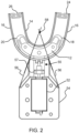
- the mouthpiece 10 comprises a base 12, an inner arch 14 for positioning adjacent an inner surface of the teeth of a jaw of the user and an outer arch 16 for positioning adjacent an outer surface of the teeth of the jaw.
- the U-shaped channel of the mouthpiece fits over the teeth of the jaw with the inner and outer arches 14, 16 positioned against the inner and outer surfaces of the teeth.
- the user can bite on the base 12 (or an insert with cleaning elements mounted on the base; not shown in Figure 1 ) because it is intended to be static in use, whereas the inner and outer arches 14, 16 are designed to move against the surface of the teeth, in the manner explained further below.
- cleaning bristles are omitted for the sake of clarity, because the focus of the invention relates to motion generation and reach.
- Bristles or tufts may be provided at various angles, length, packing density etc. on various parts of the mouthpiece: the inner arch, the outer arch and the stationary base.
- bristles on the base for the biting surfaces of the teeth or bristles may reach across from the sides to contact the biting surfaces. It is preferred that a tooth-contacting part with cleaning elements (bristles) is added on top of the base to enable brushing the occlusal tooth surfaces.
- the external part 50 has an actuator 52 for applying movement to the inner arch and/or the outer arch, relative to the base.
- an actuator 52 for applying movement to the inner arch and/or the outer arch, relative to the base.
- the actuator 52 is in front of the mouthpiece and therefore connects most simply with the outer arch 16, as shown. It could however connect to the inner arch 14.
- the actuator is inside the user's mouth within the U-shaped space formed by the inner arch, it may most easily connect to the inner arch instead of the outer arch.
- the base 12, the inner arch 14 and the outer arch 16 are coupled by a coupling arrangement 18, 20.
- the coupling arrangement 18, 20 converts movement of one of the inner and outer arches in one direction relative to the base to movement in an opposite direction relative to the base of the other of the inner and outer arches.
- each coupling arrangement connects between adjacent regions of the inner and outer arches. These regions are adacent, in that they are located at the same angular position around the jaw.
- the coupling arrangement connects between those adjacent regions.
- the coupling arrangements for examle perform a pivot funciton.
- the actuator 52 imparts movement to the outer arch 16, and the coupling arrangement 18, 20 converts this movement to an anti-phase movement (i.e. in an opposite direction) of the inner arch.
- opposite direction is not necessarily meant a perfectly opposite movement vector. Instead, one direction is generally across the edge surfaces of the teeth from one side of the jaw to the other (e.g. right to left), and the opposite direction is generally across the edge surfaces of the teeth from the other side of the jaw to the one side of the jaw (e.g. from left to right).
- the coupling arrangement 18, 20 is not clamped when the user bites down, but is free to move. This may be enabled be providing the coupling arrangement at a different level to the tooth-contacting part of the base 12.
- the cleaning system thus has inner and outer arches for brushing the inner and outer surfaces of the teeth.
- the base is a central stationary part.
- the anti-phase coupling assists in providing reach to the rear molars and also provides cancellation of vibrations and hence reduces the shaking of the device inside the mouth.
- the separation of the base from the arches means the user can bite down on the base without affecting the brushing performance. Biting on the mouthpiece will not cause an increased load on the motor, and hence will not dampen the driven vibrations.
- the system enables the desired brushing motion along the tooth arch to be implemented with sufficient transfer of energy to remove plaque and stains.
- the coupling arrangement comprises coupling members 18, 20 each extending between the inner and outer aches 14, 16.
- the coupling members 18, 20 each connect to the base 12 at a location 22 between the inner and outer arches, via a flexible strut or web.
- the coupling members 18, 20 and flexible struts function as hinges, with a main pivot point of the hinges being defined at some point on a flexible connecting member which extends between the base 12 and the location 22 where the coupling members connect to the base.
- the hinges thus rock about the pivot point to provide the anti-phase movement of the inner and outer arches.
- Figure 1 shows that the actuator 52 is mounted in a frame 54.
- the frame 54 is rigidly coupled to the base 12 by a support plate 55 (shown more clearly in other figures) so that the base and the frame are static parts of the system.
- the frame 54 also connects to the outer arch 16 by limbs 56.
- These limbs 56 provide a movable coupling between the main body of the frame and the outer arch 16.
- the limbs 56 allow rotation of the outer arch relative to the frame 54 about a rotation axis 58 behind the front of the mouthpiece. This movement is shown by arrow 60.
- the coupling arrangement comprises a first coupling member in the form of a hinge 18 along a first lateral side of the mouthpiece (the left side of the user's jaw) set forward from the back of the first lateral side.
- This first hinge 18 connects the inner arch, the outer arch and the base at that first lateral side.
- a second hinge 20 is along the other lateral side of the mouthpiece (the right side of the user's jaw) set forward from the back of the other lateral side.
- the second hinge 20 connects the inner arch, the outer arch and the base at that second lateral side.
- the coupling arrangement thus comprises hinges set forward from the back of the arches.
- the coupling arrangement additionally has a first connector 24 between the inner and outer arches 14, 16 at the back of the first lateral side and a second connector 26 between the inner and outer arches at the back of the second lateral side.
- These connectors 24, 26 maintain the desired spacing between the inner and outer arches and allow a transfer of the anti-phase movement, but the anti-phase motion is initially generated by the first and second hinges 18, 20.
- the actuator 52 in this example comprises a motor, with a rotating output shaft.
- An eccentric coupling 57 converts the rotation into a desired movement of the outer arch 16.
- This desired movement may be a simple lateral oscillation (i.e. left to right), or it may be a more complex motion, such as a motion in a 2D plane (i.e. left to right and up-down, i.e. in a vertical plane in a normal orientation of the device) such as a circular motion. It may even be a 3D motion, with a component in the 2D plane (the vertical plane) as well a component parallel to the output shaft axis. This may be used to provide an additional tapping effect.
- the actuator applies a lateral 1 dimensional translational motion, thus providing movement of the arch along a single side-to-side axis. More complex motions are however possible. A combination of a tapping motion (i.e. in a direction across rather than along the tooth) and a sliding motion may enhance the cleaning result.
- An eccentric motor may for example be integrated in the handle of the mouthpiece to actuate the outer arch with suitable frequencies in the range of 0.5-300 Hz and strokes of about 0.5-10 mm to obtain a large range of reach towards the back teeth.
- Figure 2 shows the design of Figure 1 from above.
- Figure 3 shows more clearly that the design of Figure 1 has two U-shaped channels 10a, 10b back to back, to enable cleaning of the teeth of both jaws at the same time. and with cleaning elements such as bristles 70 projecting inwardly (towards the teeth) from the inner and outer arches.
- Figure 4 shows one unit which is an assembly of one U-shaped channel 10a of the mouthpiece 10 and one frame 54a (which connects to the outer arch) and excluding the support plate 55, which is a separate part.
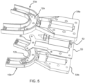
- Figure 5 shows an exploded view of the design of Figures 1 to 4 .
- the support plate 55 carries the actuator 52, and it is sandwiched between the first and second frames 54a, 54b.
- the support plate has a mounting region 80 to which the bases 12a, 12b of the two U-shaped channels 10a, 10b of the mouthpiece 10 connect.
- the two bases and the mounting region are for example clamped together with bolts or screws.
- Figure 6 shows the shape of the mouthpiece 10 and the part of the frame 54 which connects to the outer arch of the mouthpiece, and how the anti-phase motion is induced by pairs of arrows pointing in different directions along the arches.
- the motion of the solid arrows takes place at one time, and the motion of the dashed arrows takes place at a subsequent time. This is provided to enable comparison with an alternative example which is shown in Figure 8 .
- Figure 7 shows how the anti-phase motion is induced using the design of the mouthpiece shown in Figure 6 .
- the actuator induces lateral movement as shown by the pair of arrows 90.
- the coupling member 20 has the main hinge pivot point defined at some point on the flexible connect between the base 12 and the location 22.
- the hinge point is in this example asymmetrically positioned between the inner and outer arches (although a symmetric arrangement is also possible, shown below).
- the movement of the outer arch is amplified (based on the ratio between the distances 92a, 92b). This compensates for a loss of motion causes by losses in the flexible hinge structure.
- the asymmetrical hinge design provides improved transfer of motion between the outer arch and the inner arch.
- the anti-phase motion amplitude may be of the order of 1mm to 5mm.
- the actuation amplitude may be around ⁇ 1.2mm with an actuation input of ⁇ 1.5mm.
- a larger actuation amplitude may be used, e.g. around 3-4 mm (half the width of a molar), for example using geared motors.
- the hinges of the coupling arrangement are set forward from the back of the mouthpiece as explained above, and there are additional connectors 24, 26.
- An advantage of the example of Figures 1 to 7 is that the coupling members transfer motion from the outer arch to the inner arch close to the actuator. This minimizes motion loss and allows the molar section to conform to the teeth.
- Figure 8 shows an alternative design, in which the coupling arrangement comprises a first hinge 18 at the back of a first lateral side (the left side) of the mouthpiece.
- This first hinge 18 connects the back of the inner arch 14, the back of the outer arch 16 and the back of the base 12 at said first lateral side.
- a second hinge 20 is at the back of the opposite lateral side (the right side) of the mouthpiece. The second hinge connects the back of the inner arch 14, the back of the outer arch 16 and the back of the base 12 at that opposite lateral side.
- This structure has fewer intricate parts.
- the hinges are shown as symmetrical in this example, with the main pivot point mid-way between the inner and outer arches. Thus, it can be seen that different hinge designs are possible with symmetric or asymmetric positioning of the main hinge.
- FIG. 9 shows a further alternative design of the coupling members 18, 20.
- a rigid strut 100 extends between the inner and outer arches, and a pivot or rocker bearing 102 provides the connection to the base 12. There is thus a T-shaped connector with a pivot point at the interconnection of the three limbs of the strut.
- the mouthpiece may be formed of a single material.
- the inner arch and outer arch are for example formed of a first material and the coupling arrangement, or portions of the coupling arrangement, are formed of a different material to the first material.
- the use of different materials enables the elastic coupling properties to be optimized.
- Figure 10A shows the design of Figure 8 and shows regions A which may be formed of a different material (material A) to the remainder of the structure.
- Figure 10B shows the design of Figure 6 and shows regions B and C which may be formed of a different material to the remainder of the structure. Regions B and C may be of the same material (material B), or they may be two different materials (materials B, C), both different to the main structure.
- Figure 10C shows the design of Figure 6 and shows regions D which may be formed of a different material (material D) to the remainder of the structure. These regions formed of a different material are the joints between the coupling members and the arches and the joints between the coupling members and the base.
- Materials A to D have for example a (relatively) low hardness and low Young's modulus to add flexibility and deformity to the hinges.
- the material of the remainder of the structure has for example a (relatively) medium or high hardness and medium or high Young's modulus.
- the main material may be polyethylene (with elastic modulus 1.1 GPa and Poisson's ratio 0.42. While this is one option of food grade material for parts with flexure design (living hinges), there are also other materials such as polyamides (e.g. Nylon) and a thermoplastic elastomer that can be used for this application.
- polyethylene with elastic modulus 1.1 GPa and Poisson's ratio 0.42. While this is one option of food grade material for parts with flexure design (living hinges), there are also other materials such as polyamides (e.g. Nylon) and a thermoplastic elastomer that can be used for this application.
- the hinges are designed for low stress, long life and minimal loss of energy in the system.
- the parts may be made by 3D printing or by injection molding, for example.
- the overall system can be described as a compliant spring system.
- the system may for example be driven at its resonance frequency, reducing the power needs of the system.
- the frequency may also be tuned individually to the resonance frequency, using feedback of the amplitude, since damping on the teeth may vary from person to person, and also parts of the system may be customized for better fitting.
- Figure 11 shows a modification in which the limbs 56 are made thinner and have a cutout 110 to create an additional degree of freedom in their movement.
- This can be used to generate a 3D motion from a 2D eccentric drive. For example, by actuating with a circular trajectory, a more complex (2D) circular brushing motion is generated. By adding another pivot point, a complex 3D motion can be generated, e.g. circular motion superimposed by a tapping motion.
- the actuator is in front of the mouthpiece, i.e. outside the mouth.
- the actuator instead of forming the actuator outside of and in front of the mouthpiece, the actuator may be arranged in a space partially surrounded by the inner arch. Thus, it may be for positioning inside the user's mouth. This may enable a more compact device.
- One option is to use a similar actuator to that shown above, for example for driving the inner arch (which is then closer to the actuator).
- Figure 12 instead shows an alternative actuator design.
- the actuator comprises a dual shaft motor 120 with swash plates at the output shafts.
- a first swash plate 122 connects to a back of one same lateral side of the inner and outer arches 14, 16, and a second swash plate 124 connects to a back of the other same lateral side of the inner and outer arches.
- each swash plate ensures opposite motion of a common end of the inner and outer arches.
- the two shafts for example rotate in the same direction.
- Figure 13 shows a further alternative actuator design.
- the actuator comprises a dual shaft motor 130, with two swash plates at the output shafts.
- a first swash plate 132 driven by one shaft connects to a back of opposite lateral sides of the inner arch 14, and a second swash plate 134 driven by the other shaft connects to a back of opposite lateral sides of the outer arch 16.
- each swash plate ensures opposite motion of the two ends of a respective one of the inner and outer arches, and the two swash plates operate in anti-phase with each other. They may for example rotate in opposite directions.
- the swash plates function as the coupling arrangement.
- the overall swash plate design again connects between adjacent regions (the ends in these examples) of the inner and outer arches, and the adjacent ends are made to move in opposite directions by the overall swash plate design.
- the U-shaped channels of the mouthpiece allow occlusal bristles to be added on the stationary base.
- the incisors bite on the front base part to hold the stationary part stationary.
- This stationary part may be covered with a (tooth-contacting) cleaning structure (e.g. rough surface or short 0.5-1 mm bristles to have some cleaning of the top incisors).
- the thickness of this stationary part can be increased to make room for occlusal bristles on the molar-premolar areas.
Landscapes
- Health & Medical Sciences (AREA)
- Dentistry (AREA)
- Epidemiology (AREA)
- Life Sciences & Earth Sciences (AREA)
- Animal Behavior & Ethology (AREA)
- General Health & Medical Sciences (AREA)
- Public Health (AREA)
- Veterinary Medicine (AREA)
- Brushes (AREA)
- Dental Tools And Instruments Or Auxiliary Dental Instruments (AREA)
Claims (15)
- Mundstück (10) für ein Zahnreinigungssystem, umfassend:eine Basis (12);einen inneren Bogen (14) zum Positionieren angrenzend an eine innere Oberfläche der Zähne eines Kiefers eines Benutzers; undeinen äußeren Bogen (16) zum Positionieren angrenzend an eine äußere Oberfläche der Zähne des Kiefers,eine Betätigungsvorrichtungskopplung zum Verbinden mit einer Betätigungsvorrichtung (52) zum Anwenden einer Bewegung auf den inneren Bogen und/oder den äußeren Bogen, relativ zur Basis,wobei die Basis (12), der innere Bogen (14) und der äußere Bogen (16) durch eine Kopplungsanordnung (18, 20) gekoppelt sind,wobei die Kopplungsanordnung mit angrenzenden Gebieten der inneren und äußeren Bögen koppelt und die Bewegung des Gebiets eines der inneren und äußeren Bögen in einer Richtung relativ zur Basis in eine Bewegung in einer entgegengesetzten Richtung relativ zur Basis des Gebiets des anderen der inneren und äußeren Bögen umwandelt.
- Mundstück nach Anspruch 1, wobei die Kopplungsanordnung Kopplungsglieder (18, 20) umfasst, die sich zwischen den inneren und äußeren Bögen erstrecken, wobei die Kopplungsglieder an einer Stelle (22) zwischen den inneren und äußeren Bögen mit der Basis verbunden sind.
- Mundstück nach Anspruch 1 oder 2, wobei die Kopplungsanordnung (18, 20) konfiguriert ist, um eine Betätigung des inneren Bogens oder des äußeren Bogens an einer Vorderseite des Mundstücks bereitzustellen:entlang einer einzelnen Seite-zu-Seite-Achse; oderinnerhalb einer zweidimensionalen Seite-zu-Seite- und Oben-Unten-Ebene.
- Mundstück nach Anspruch 2 oder 3, wobei die Kopplungsanordnung folgendes umfasst:ein erstes Scharnier (18) an der Rückseite einer ersten lateralen Seite des Mundstücks, wobei das erste Scharnier einen Rückseitenabschnitt des inneren Bogens, einen Rückseitenabschnitt des äußeren Bogens und die Basis an der ersten lateralen Seite verbindet; undein zweites Scharnier (20) an einem Rückseitenabschnitt einer zweiten lateralen Seite des Mundstücks, wobei das zweite Scharnier einen Rückseitenabschnitt des inneren Bogens, einen Rückseitenabschnitt des äußeren Bogens und die Basis an der zweiten lateralen Seite verbindet.
- Mundstück nach Anspruch 2 oder 3, wobei die Kopplungsanordnung folgendes umfasst:ein erstes Scharnier (18) entlang einer ersten lateralen Seite des Mundstücks, das von der Rückseite der ersten lateralen Seite nach vorne versetzt ist, wobei das erste Scharnier den inneren Bogen, den äußeren Bogen und die Basis an dieser ersten lateralen Seite verbindet; undein zweites Scharnier (20) entlang einer zweiten lateralen Seite des Mundstücks, das von der Rückseite der zweiten lateralen Seite nach vorne versetzt ist, wobei das zweite Scharnier den inneren Bogen, den äußeren Bogen und die Basis an dieser zweiten lateralen Seite verbindet.
- Mundstück nach Anspruch 5, wobei die Kopplungsanordnung weiter einen ersten Verbinder (24) zwischen dem inneren und dem äußeren Bogen auf der Rückseite der ersten lateralen Seite und einen zweiten Verbinder (26) zwischen dem inneren und dem äußeren Bogen auf der Rückseite der zweiten lateralen Seite umfasst.
- Mundstück nach einem der Ansprüche 4 bis 6, wobei das erste und das zweite Scharnier (18, 20) jeweils folgendes umfassen:eine Strebe (100), die über einen entlang der Strebe lokalisierten Schwenkpunkt (102) starr mit dem inneren und äußeren Bogen gekoppelt ist, der mit der Basis gekoppelt ist; odereine erste U-Biegung oder W-Biegung zwischen dem äußeren Bogen (16) und einem Verbindungsknoten (22) und eine zweite U-Biegung oder W-Biegung zwischen dem Verbindungsknoten (22) und dem inneren Bogen (14), wobei der Verbindungsknoten (22) mit der Basis (12) gekoppelt ist.
- Mundstück nach Anspruch 7, wobei der innere Bogen und der äußere Bogen aus einem ersten Material ausgebildet sind und die Kopplungsanordnung (18, 20) oder Abschnitte der Kopplungsanordnung aus einem anderen Material als dem ersten Material ausgebildet sind.
- Zahnreinigungssystem, umfassend:das Mundstück nach einem der Ansprüche 1 bis 8;eine Betätigungsvorrichtung, die mit der Kopplung des Mundstücks gekoppelt ist.
- Zahnreinigungssystem nach Anspruch 9, wobei die Betätigungsvorrichtung (52) vor dem Mundstück angeordnet ist und mit dem äußeren Bogen (16) an der Vorderseite des Mundstücks gekoppelt ist.
- Zahnreinigungssystem nach Anspruch 10, weiter umfassend einen Rahmen (54), der die Betätigungsvorrichtung (52) trägt, wobei der Rahmen starr mit der Basis (12) gekoppelt ist, wobei der Rahmen (54) mit dem äußeren Bogen (16) mit einer Verbindung (56) gekoppelt ist, die eine Drehung des äußeren Bogens (16) relativ zum Rahmen (54) um eine Drehachse (58) hinter der Vorderseite des Mundstücks erlaubt.
- Zahnreinigungssystem nach einem der Ansprüche 9 bis 11, wobei die Betätigungsvorrichtung (52) einen Motor mit einem exzentrischen Kopplungselement (57) umfasst, das mit dem äußeren Bogen (16) verbunden ist.
- Zahnreinigungssystem nach Anspruch 9, wobei die Betätigungsvorrichtung (52) in einem Raum angeordnet ist, der teilweise von dem inneren Bogen (14) umgeben ist.
- Zahnreinigungssystem, umfassend:
ein Mundstück (10) für ein Zahnreinigungssystem, umfassend:einen inneren Bogen (14) zum Positionieren angrenzend an eine innere Oberfläche der Zähne eines Kiefers eines Benutzers; undeinen äußeren Bogen (16) zum Positionieren angrenzend an eine äußere Oberfläche der Zähne des Kiefers,eine Betätigungsvorrichtungskopplung zum Verbinden mit einer Betätigungsvorrichtung zum Anwenden einer Bewegung auf den inneren Bogen und/oder den äußeren Bogen,wobei das Zahnreinigungssystem weiter eine Betätigungsvorrichtung umfasst, die mit der Kopplung des Mundstücks gekoppelt ist,wobei der innere Bogen (14) und der äußere Bogen (16) durch eine Kopplungsanordnung gekoppelt sind,wobei die Kopplungsanordnung eine erste und eine zweite Taumelscheibe am Ausgang der Betätigungsvorrichtung umfasst, wobei:die erste Taumelscheibe (132) mit einer Rückseite von gegenüberliegenden lateralen Seiten des inneren Bogens verbunden ist und die zweite Taumelscheibe (134) mit einer Rückseite von gegenüberliegenden lateralen Seiten des äußeren Bogens verbunden ist; oderdie erste Taumelscheibe (122) mit einer Rückseite einer gleichen lateralen Seite des inneren und äußeren Bogens verbunden ist und die zweite Taumelscheibe (124) mit einer Rückseite der anderen gleichen lateralen Seite des inneren und äußeren Bogens verbunden ist. - Zahnreinigungssystem nach einem vorstehenden Anspruch, weiter umfassend Reinigungselemente (70) auf dem inneren Bogen (14) und dem äußeren Bogen (16) sowie ein strukturelles Reinigungselement, das oben auf der Basis (12) montiert ist.
Applications Claiming Priority (2)
| Application Number | Priority Date | Filing Date | Title |
|---|---|---|---|
| EP20169724.0A EP3895657A1 (de) | 2020-04-15 | 2020-04-15 | Mundstück für ein zahnreinigungssystem sowie zahnreinigungssystem |
| PCT/EP2021/058981 WO2021209288A1 (en) | 2020-04-15 | 2021-04-07 | Mouthpiece for a dental cleaning system and the dental cleaning system |
Publications (3)
| Publication Number | Publication Date |
|---|---|
| EP4135619A1 EP4135619A1 (de) | 2023-02-22 |
| EP4135619B1 true EP4135619B1 (de) | 2024-11-13 |
| EP4135619C0 EP4135619C0 (de) | 2024-11-13 |
Family
ID=70292781
Family Applications (2)
| Application Number | Title | Priority Date | Filing Date |
|---|---|---|---|
| EP20169724.0A Withdrawn EP3895657A1 (de) | 2020-04-15 | 2020-04-15 | Mundstück für ein zahnreinigungssystem sowie zahnreinigungssystem |
| EP21716443.3A Active EP4135619B1 (de) | 2020-04-15 | 2021-04-07 | Mundstück für ein zahnreinigungssystem sowie zahnreinigungssystem |
Family Applications Before (1)
| Application Number | Title | Priority Date | Filing Date |
|---|---|---|---|
| EP20169724.0A Withdrawn EP3895657A1 (de) | 2020-04-15 | 2020-04-15 | Mundstück für ein zahnreinigungssystem sowie zahnreinigungssystem |
Country Status (5)
| Country | Link |
|---|---|
| US (1) | US12427006B2 (de) |
| EP (2) | EP3895657A1 (de) |
| JP (1) | JP7672424B2 (de) |
| BR (1) | BR112022020752A2 (de) |
| WO (1) | WO2021209288A1 (de) |
Families Citing this family (3)
| Publication number | Priority date | Publication date | Assignee | Title |
|---|---|---|---|---|
| US11622872B2 (en) * | 2016-05-16 | 2023-04-11 | Elixir Medical Corporation | Uncaging stent |
| DE102023120053A1 (de) * | 2023-07-27 | 2025-01-30 | epitome GmbH | Vorrichtung zum Reinigen von Oberflächen und deren Verwendung |
| DE102024107671A1 (de) * | 2023-08-07 | 2025-02-13 | epitome GmbH | Vorrichtung zum Ausführen von Reinigungs- oder Detektionsvorgängen und Vorrichtung zum Positionieren von Einrichtungen im Mundraum |
Family Cites Families (12)
| Publication number | Priority date | Publication date | Assignee | Title |
|---|---|---|---|---|
| JPH09252843A (ja) * | 1996-03-26 | 1997-09-30 | Matsushita Electric Works Ltd | 電動歯ブラシ |
| KR100397187B1 (ko) * | 2000-12-12 | 2003-09-06 | 고경용 | 전동 칫솔 |
| JP5275343B2 (ja) | 2007-05-22 | 2013-08-28 | コーニンクレッカ フィリップス エレクトロニクス エヌ ヴィ | 歯をクリーニングするための口内電気器具 |
| US20090276972A1 (en) * | 2008-05-08 | 2009-11-12 | Dugan David M | Tooth brushing system |
| EP2331004B1 (de) * | 2008-10-01 | 2023-06-07 | Koninklijke Philips N.V. | Unterteiltes mundstück für die mundpflege |
| CN104586523B (zh) * | 2010-06-22 | 2016-08-24 | 皇家飞利浦有限公司 | 具有机械传动机构的用于清洁牙齿的牙套 |
| US8631531B2 (en) * | 2011-07-13 | 2014-01-21 | Robert Garner | Apparatus and method for brushing teeth |
| US8635731B2 (en) * | 2011-07-13 | 2014-01-28 | Robert Garner | Teethbrush |
| US10888201B2 (en) * | 2014-11-11 | 2021-01-12 | ZeroBrush, Inc. | Systems, devices, and methods for providing customized oral care agents |
| US11278385B2 (en) * | 2017-04-25 | 2022-03-22 | Dentver Ltd. | Toothbrush conforming to dental arch and corresponding devices and methods |
| ES2908565T3 (es) * | 2018-01-19 | 2022-05-03 | Blbr Gmbh | Dispositivo de limpieza dental y estructura portadora para boquilla de un dispositivo de limpieza dental |
| EP4282378A1 (de) * | 2022-05-24 | 2023-11-29 | Koninklijke Philips N.V. | Mundpflegevorrichtung |
-
2020
- 2020-04-15 EP EP20169724.0A patent/EP3895657A1/de not_active Withdrawn
-
2021
- 2021-04-07 EP EP21716443.3A patent/EP4135619B1/de active Active
- 2021-04-07 US US17/918,683 patent/US12427006B2/en active Active
- 2021-04-07 JP JP2022562277A patent/JP7672424B2/ja active Active
- 2021-04-07 BR BR112022020752A patent/BR112022020752A2/pt not_active Application Discontinuation
- 2021-04-07 WO PCT/EP2021/058981 patent/WO2021209288A1/en not_active Ceased
Also Published As
| Publication number | Publication date |
|---|---|
| WO2021209288A1 (en) | 2021-10-21 |
| US20230145447A1 (en) | 2023-05-11 |
| JP2023521816A (ja) | 2023-05-25 |
| US12427006B2 (en) | 2025-09-30 |
| JP7672424B2 (ja) | 2025-05-07 |
| CN115768377A (zh) | 2023-03-07 |
| BR112022020752A2 (pt) | 2022-12-20 |
| EP4135619C0 (de) | 2024-11-13 |
| EP4135619A1 (de) | 2023-02-22 |
| EP3895657A1 (de) | 2021-10-20 |
Similar Documents
| Publication | Publication Date | Title |
|---|---|---|
| EP4135619B1 (de) | Mundstück für ein zahnreinigungssystem sowie zahnreinigungssystem | |
| JP4778440B2 (ja) | 歯ブラシ | |
| RU2521828C2 (ru) | Система для осевого движения щетинок в капе для очистки зубов | |
| EP2467091B1 (de) | Freihändige Mundpflegevorrichtung | |
| US9980796B2 (en) | Ultrasound applicator | |
| JP3731209B2 (ja) | 口腔内衛生装置 | |
| RU2012132196A (ru) | Приспособление для ухода за полостью рта (варианты) | |
| CN101730512A (zh) | 电动牙刷 | |
| JP2018504968A (ja) | 多頭型歯ブラシ | |
| KR102343997B1 (ko) | 브러시헤드 | |
| CN115768377B (zh) | 用于牙齿清洁系统的口腔件和牙齿清洁系统 | |
| JP4762451B2 (ja) | 動力駆動歯ブラシ | |
| EP4281004B1 (de) | Mundstück zur mundpflege verbunden mit grösserer masse für erhöhte vibration | |
| RU2559015C2 (ru) | Чистящая секция электрического устройства для гигиены полости рта | |
| KR102762808B1 (ko) | 칫솔모 설치 구조 | |
| JP2003339744A (ja) | 動力駆動歯ブラシ | |
| CN222426624U (zh) | 吞咽障碍咽腔内刺激训练器及其吞咽训练振动件 | |
| CN222398897U (zh) | 电动牙刷及其刷头 | |
| CN119546206A (zh) | 口腔护理设备 | |
| CN118265505A (zh) | 一种牙齿清洁系统 | |
| HK40014411A (en) | Tooth cleaning device with integrated drive device | |
| HK40014411B (en) | Tooth cleaning device with integrated drive device |
Legal Events
| Date | Code | Title | Description |
|---|---|---|---|
| STAA | Information on the status of an ep patent application or granted ep patent |
Free format text: STATUS: UNKNOWN |
|
| STAA | Information on the status of an ep patent application or granted ep patent |
Free format text: STATUS: THE INTERNATIONAL PUBLICATION HAS BEEN MADE |
|
| PUAI | Public reference made under article 153(3) epc to a published international application that has entered the european phase |
Free format text: ORIGINAL CODE: 0009012 |
|
| STAA | Information on the status of an ep patent application or granted ep patent |
Free format text: STATUS: REQUEST FOR EXAMINATION WAS MADE |
|
| 17P | Request for examination filed |
Effective date: 20221115 |
|
| AK | Designated contracting states |
Kind code of ref document: A1 Designated state(s): AL AT BE BG CH CY CZ DE DK EE ES FI FR GB GR HR HU IE IS IT LI LT LU LV MC MK MT NL NO PL PT RO RS SE SI SK SM TR |
|
| DAV | Request for validation of the european patent (deleted) | ||
| DAX | Request for extension of the european patent (deleted) | ||
| STAA | Information on the status of an ep patent application or granted ep patent |
Free format text: STATUS: EXAMINATION IS IN PROGRESS |
|
| 17Q | First examination report despatched |
Effective date: 20231010 |
|
| GRAP | Despatch of communication of intention to grant a patent |
Free format text: ORIGINAL CODE: EPIDOSNIGR1 |
|
| STAA | Information on the status of an ep patent application or granted ep patent |
Free format text: STATUS: GRANT OF PATENT IS INTENDED |
|
| INTG | Intention to grant announced |
Effective date: 20240607 |
|
| GRAS | Grant fee paid |
Free format text: ORIGINAL CODE: EPIDOSNIGR3 |
|
| GRAA | (expected) grant |
Free format text: ORIGINAL CODE: 0009210 |
|
| STAA | Information on the status of an ep patent application or granted ep patent |
Free format text: STATUS: THE PATENT HAS BEEN GRANTED |
|
| AK | Designated contracting states |
Kind code of ref document: B1 Designated state(s): AL AT BE BG CH CY CZ DE DK EE ES FI FR GB GR HR HU IE IS IT LI LT LU LV MC MK MT NL NO PL PT RO RS SE SI SK SM TR |
|
| REG | Reference to a national code |
Ref country code: GB Ref legal event code: FG4D |
|
| REG | Reference to a national code |
Ref country code: CH Ref legal event code: EP |
|
| REG | Reference to a national code |
Ref country code: IE Ref legal event code: FG4D |
|
| REG | Reference to a national code |
Ref country code: DE Ref legal event code: R096 Ref document number: 602021021773 Country of ref document: DE |
|
| U01 | Request for unitary effect filed |
Effective date: 20241113 |
|
| U07 | Unitary effect registered |
Designated state(s): AT BE BG DE DK EE FI FR IT LT LU LV MT NL PT RO SE SI Effective date: 20241119 |
|
| PG25 | Lapsed in a contracting state [announced via postgrant information from national office to epo] |
Ref country code: IS Free format text: LAPSE BECAUSE OF FAILURE TO SUBMIT A TRANSLATION OF THE DESCRIPTION OR TO PAY THE FEE WITHIN THE PRESCRIBED TIME-LIMIT Effective date: 20250313 Ref country code: HR Free format text: LAPSE BECAUSE OF FAILURE TO SUBMIT A TRANSLATION OF THE DESCRIPTION OR TO PAY THE FEE WITHIN THE PRESCRIBED TIME-LIMIT Effective date: 20241113 |
|
| PG25 | Lapsed in a contracting state [announced via postgrant information from national office to epo] |
Ref country code: ES Free format text: LAPSE BECAUSE OF FAILURE TO SUBMIT A TRANSLATION OF THE DESCRIPTION OR TO PAY THE FEE WITHIN THE PRESCRIBED TIME-LIMIT Effective date: 20241113 |
|
| PG25 | Lapsed in a contracting state [announced via postgrant information from national office to epo] |
Ref country code: NO Free format text: LAPSE BECAUSE OF FAILURE TO SUBMIT A TRANSLATION OF THE DESCRIPTION OR TO PAY THE FEE WITHIN THE PRESCRIBED TIME-LIMIT Effective date: 20250213 |
|
| PG25 | Lapsed in a contracting state [announced via postgrant information from national office to epo] |
Ref country code: GR Free format text: LAPSE BECAUSE OF FAILURE TO SUBMIT A TRANSLATION OF THE DESCRIPTION OR TO PAY THE FEE WITHIN THE PRESCRIBED TIME-LIMIT Effective date: 20250214 |
|
| PG25 | Lapsed in a contracting state [announced via postgrant information from national office to epo] |
Ref country code: PL Free format text: LAPSE BECAUSE OF FAILURE TO SUBMIT A TRANSLATION OF THE DESCRIPTION OR TO PAY THE FEE WITHIN THE PRESCRIBED TIME-LIMIT Effective date: 20241113 |
|
| PG25 | Lapsed in a contracting state [announced via postgrant information from national office to epo] |
Ref country code: RS Free format text: LAPSE BECAUSE OF FAILURE TO SUBMIT A TRANSLATION OF THE DESCRIPTION OR TO PAY THE FEE WITHIN THE PRESCRIBED TIME-LIMIT Effective date: 20250213 |
|
| U20 | Renewal fee for the european patent with unitary effect paid |
Year of fee payment: 5 Effective date: 20250430 |
|
| PG25 | Lapsed in a contracting state [announced via postgrant information from national office to epo] |
Ref country code: SM Free format text: LAPSE BECAUSE OF FAILURE TO SUBMIT A TRANSLATION OF THE DESCRIPTION OR TO PAY THE FEE WITHIN THE PRESCRIBED TIME-LIMIT Effective date: 20241113 |
|
| PG25 | Lapsed in a contracting state [announced via postgrant information from national office to epo] |
Ref country code: SK Free format text: LAPSE BECAUSE OF FAILURE TO SUBMIT A TRANSLATION OF THE DESCRIPTION OR TO PAY THE FEE WITHIN THE PRESCRIBED TIME-LIMIT Effective date: 20241113 |
|
| PG25 | Lapsed in a contracting state [announced via postgrant information from national office to epo] |
Ref country code: CZ Free format text: LAPSE BECAUSE OF FAILURE TO SUBMIT A TRANSLATION OF THE DESCRIPTION OR TO PAY THE FEE WITHIN THE PRESCRIBED TIME-LIMIT Effective date: 20241113 |
|
| PLBE | No opposition filed within time limit |
Free format text: ORIGINAL CODE: 0009261 |
|
| STAA | Information on the status of an ep patent application or granted ep patent |
Free format text: STATUS: NO OPPOSITION FILED WITHIN TIME LIMIT |
|
| 26N | No opposition filed |
Effective date: 20250814 |
|
| REG | Reference to a national code |
Ref country code: CH Ref legal event code: H13 Free format text: ST27 STATUS EVENT CODE: U-0-0-H10-H13 (AS PROVIDED BY THE NATIONAL OFFICE) Effective date: 20251125 |