EP4135113A1 - Separator for electrochemical device and method for manufacturing same - Google Patents
Separator for electrochemical device and method for manufacturing same Download PDFInfo
- Publication number
- EP4135113A1 EP4135113A1 EP21789255.3A EP21789255A EP4135113A1 EP 4135113 A1 EP4135113 A1 EP 4135113A1 EP 21789255 A EP21789255 A EP 21789255A EP 4135113 A1 EP4135113 A1 EP 4135113A1
- Authority
- EP
- European Patent Office
- Prior art keywords
- separator
- binder resin
- electrochemical device
- present disclosure
- coating layer
- Prior art date
- Legal status (The legal status is an assumption and is not a legal conclusion. Google has not performed a legal analysis and makes no representation as to the accuracy of the status listed.)
- Pending
Links
Images


Classifications
-
- H—ELECTRICITY
- H01—ELECTRIC ELEMENTS
- H01M—PROCESSES OR MEANS, e.g. BATTERIES, FOR THE DIRECT CONVERSION OF CHEMICAL ENERGY INTO ELECTRICAL ENERGY
- H01M10/00—Secondary cells; Manufacture thereof
- H01M10/05—Accumulators with non-aqueous electrolyte
- H01M10/052—Li-accumulators
-
- H—ELECTRICITY
- H01—ELECTRIC ELEMENTS
- H01M—PROCESSES OR MEANS, e.g. BATTERIES, FOR THE DIRECT CONVERSION OF CHEMICAL ENERGY INTO ELECTRICAL ENERGY
- H01M50/00—Constructional details or processes of manufacture of the non-active parts of electrochemical cells other than fuel cells, e.g. hybrid cells
- H01M50/40—Separators; Membranes; Diaphragms; Spacing elements inside cells
- H01M50/409—Separators, membranes or diaphragms characterised by the material
- H01M50/446—Composite material consisting of a mixture of organic and inorganic materials
-
- H—ELECTRICITY
- H01—ELECTRIC ELEMENTS
- H01M—PROCESSES OR MEANS, e.g. BATTERIES, FOR THE DIRECT CONVERSION OF CHEMICAL ENERGY INTO ELECTRICAL ENERGY
- H01M50/00—Constructional details or processes of manufacture of the non-active parts of electrochemical cells other than fuel cells, e.g. hybrid cells
- H01M50/40—Separators; Membranes; Diaphragms; Spacing elements inside cells
- H01M50/409—Separators, membranes or diaphragms characterised by the material
- H01M50/449—Separators, membranes or diaphragms characterised by the material having a layered structure
- H01M50/451—Separators, membranes or diaphragms characterised by the material having a layered structure comprising layers of only organic material and layers containing inorganic material
-
- H—ELECTRICITY
- H01—ELECTRIC ELEMENTS
- H01M—PROCESSES OR MEANS, e.g. BATTERIES, FOR THE DIRECT CONVERSION OF CHEMICAL ENERGY INTO ELECTRICAL ENERGY
- H01M10/00—Secondary cells; Manufacture thereof
- H01M10/05—Accumulators with non-aqueous electrolyte
- H01M10/052—Li-accumulators
- H01M10/0525—Rocking-chair batteries, i.e. batteries with lithium insertion or intercalation in both electrodes; Lithium-ion batteries
-
- H—ELECTRICITY
- H01—ELECTRIC ELEMENTS
- H01M—PROCESSES OR MEANS, e.g. BATTERIES, FOR THE DIRECT CONVERSION OF CHEMICAL ENERGY INTO ELECTRICAL ENERGY
- H01M4/00—Electrodes
- H01M4/02—Electrodes composed of, or comprising, active material
- H01M4/62—Selection of inactive substances as ingredients for active masses, e.g. binders, fillers
- H01M4/621—Binders
- H01M4/622—Binders being polymers
-
- H—ELECTRICITY
- H01—ELECTRIC ELEMENTS
- H01M—PROCESSES OR MEANS, e.g. BATTERIES, FOR THE DIRECT CONVERSION OF CHEMICAL ENERGY INTO ELECTRICAL ENERGY
- H01M50/00—Constructional details or processes of manufacture of the non-active parts of electrochemical cells other than fuel cells, e.g. hybrid cells
- H01M50/40—Separators; Membranes; Diaphragms; Spacing elements inside cells
- H01M50/409—Separators, membranes or diaphragms characterised by the material
- H01M50/411—Organic material
- H01M50/414—Synthetic resins, e.g. thermoplastics or thermosetting resins
- H01M50/417—Polyolefins
-
- H—ELECTRICITY
- H01—ELECTRIC ELEMENTS
- H01M—PROCESSES OR MEANS, e.g. BATTERIES, FOR THE DIRECT CONVERSION OF CHEMICAL ENERGY INTO ELECTRICAL ENERGY
- H01M50/00—Constructional details or processes of manufacture of the non-active parts of electrochemical cells other than fuel cells, e.g. hybrid cells
- H01M50/40—Separators; Membranes; Diaphragms; Spacing elements inside cells
- H01M50/409—Separators, membranes or diaphragms characterised by the material
- H01M50/411—Organic material
- H01M50/414—Synthetic resins, e.g. thermoplastics or thermosetting resins
- H01M50/42—Acrylic resins
-
- H—ELECTRICITY
- H01—ELECTRIC ELEMENTS
- H01M—PROCESSES OR MEANS, e.g. BATTERIES, FOR THE DIRECT CONVERSION OF CHEMICAL ENERGY INTO ELECTRICAL ENERGY
- H01M50/00—Constructional details or processes of manufacture of the non-active parts of electrochemical cells other than fuel cells, e.g. hybrid cells
- H01M50/40—Separators; Membranes; Diaphragms; Spacing elements inside cells
- H01M50/409—Separators, membranes or diaphragms characterised by the material
- H01M50/431—Inorganic material
-
- H—ELECTRICITY
- H01—ELECTRIC ELEMENTS
- H01M—PROCESSES OR MEANS, e.g. BATTERIES, FOR THE DIRECT CONVERSION OF CHEMICAL ENERGY INTO ELECTRICAL ENERGY
- H01M50/00—Constructional details or processes of manufacture of the non-active parts of electrochemical cells other than fuel cells, e.g. hybrid cells
- H01M50/40—Separators; Membranes; Diaphragms; Spacing elements inside cells
- H01M50/46—Separators, membranes or diaphragms characterised by their combination with electrodes
-
- H—ELECTRICITY
- H01—ELECTRIC ELEMENTS
- H01M—PROCESSES OR MEANS, e.g. BATTERIES, FOR THE DIRECT CONVERSION OF CHEMICAL ENERGY INTO ELECTRICAL ENERGY
- H01M50/00—Constructional details or processes of manufacture of the non-active parts of electrochemical cells other than fuel cells, e.g. hybrid cells
- H01M50/40—Separators; Membranes; Diaphragms; Spacing elements inside cells
- H01M50/489—Separators, membranes, diaphragms or spacing elements inside the cells, characterised by their physical properties, e.g. swelling degree, hydrophilicity or shut down properties
- H01M50/491—Porosity
-
- H—ELECTRICITY
- H01—ELECTRIC ELEMENTS
- H01M—PROCESSES OR MEANS, e.g. BATTERIES, FOR THE DIRECT CONVERSION OF CHEMICAL ENERGY INTO ELECTRICAL ENERGY
- H01M4/00—Electrodes
- H01M4/02—Electrodes composed of, or comprising, active material
- H01M4/36—Selection of substances as active materials, active masses, active liquids
- H01M4/48—Selection of substances as active materials, active masses, active liquids of inorganic oxides or hydroxides
- H01M4/50—Selection of substances as active materials, active masses, active liquids of inorganic oxides or hydroxides of manganese
- H01M4/505—Selection of substances as active materials, active masses, active liquids of inorganic oxides or hydroxides of manganese of mixed oxides or hydroxides containing manganese for inserting or intercalating light metals, e.g. LiMn2O4 or LiMn2OxFy
-
- H—ELECTRICITY
- H01—ELECTRIC ELEMENTS
- H01M—PROCESSES OR MEANS, e.g. BATTERIES, FOR THE DIRECT CONVERSION OF CHEMICAL ENERGY INTO ELECTRICAL ENERGY
- H01M4/00—Electrodes
- H01M4/02—Electrodes composed of, or comprising, active material
- H01M4/36—Selection of substances as active materials, active masses, active liquids
- H01M4/48—Selection of substances as active materials, active masses, active liquids of inorganic oxides or hydroxides
- H01M4/52—Selection of substances as active materials, active masses, active liquids of inorganic oxides or hydroxides of nickel, cobalt or iron
- H01M4/525—Selection of substances as active materials, active masses, active liquids of inorganic oxides or hydroxides of nickel, cobalt or iron of mixed oxides or hydroxides containing iron, cobalt or nickel for inserting or intercalating light metals, e.g. LiNiO2, LiCoO2 or LiCoOxFy
-
- Y—GENERAL TAGGING OF NEW TECHNOLOGICAL DEVELOPMENTS; GENERAL TAGGING OF CROSS-SECTIONAL TECHNOLOGIES SPANNING OVER SEVERAL SECTIONS OF THE IPC; TECHNICAL SUBJECTS COVERED BY FORMER USPC CROSS-REFERENCE ART COLLECTIONS [XRACs] AND DIGESTS
- Y02—TECHNOLOGIES OR APPLICATIONS FOR MITIGATION OR ADAPTATION AGAINST CLIMATE CHANGE
- Y02E—REDUCTION OF GREENHOUSE GAS [GHG] EMISSIONS, RELATED TO ENERGY GENERATION, TRANSMISSION OR DISTRIBUTION
- Y02E60/00—Enabling technologies; Technologies with a potential or indirect contribution to GHG emissions mitigation
- Y02E60/10—Energy storage using batteries
Definitions
- the present application claims priority to Korean Patent Application No. 10-2020-0045488 filed on April 14, 2020 in the Republic of Korea.
- the present disclosure relates to a separator used for an electrochemical device, such as a secondary battery, and a method for manufacturing the same.
- a polyolefin-based microporous film used conventionally as a separator for an electrochemical device shows a severe heat shrinking behavior at a temperature of 100°C or higher due to its material property and a characteristic during its manufacturing process, including orientation, thereby causing a short-circuit between a positive electrode and a negative electrode.
- a separator having a porous coating layer including a mixture containing inorganic particles and a binder polymer on at least one surface of a separator substrate, such as a polyolefin-based microporous membrane, having a plurality of pores.
- the binder polymer used for the porous coating layer includes a PVdF-based binder resin including vinylidene as a polymerization unit.
- a PVdF-based binder resin including vinylidene as a polymerization unit.
- the present disclosure is designed to solve the problems of the related art, and therefore the present disclosure is directed to providing a separator for an electrochemical device which has improved adhesion to an electrode and shows a low shrinkage, and a method for manufacturing the same.
- the present disclosure is also directed to providing a binder resin composition used for the separator. It will be easily understood that the objects and advantages of the present disclosure may be realized by the means shown in the appended claims and combinations thereof.
- a separator for an electrochemical device which includes a porous separator substrate and a porous coating layer formed on the surface of the substrate,
- the separator for an electrochemical device as defined in the first embodiment, wherein the binder resin further includes a third binder resin, which is a polymer of a polymerization unit having at least one selected from acrylate, acetate and nitrile groups.
- a third binder resin which is a polymer of a polymerization unit having at least one selected from acrylate, acetate and nitrile groups.
- the separator for an electrochemical device as defined in the first or the second embodiment, wherein the first binder resin is present in an amount of 50-90 wt% based on 100 wt% of the binder resin, and the second binder resin is present in an amount of 10-50 wt% based on 100 wt% of the binder resin.
- the separator for an electrochemical device as defined in any one of the first to the third embodiments, wherein the third binder resin is present in an amount of 7 wt% or less based on 100 wt% of the binder resin.
- the separator for an electrochemical device as defined in any one of the first to the fourth embodiments, wherein the first polymer resin has a molecular weight (Mw) of 100,000-500,000 and includes polyvinyl acetate (PVAc) represented by the following Chemical Formula 1: wherein n is an integer of 1 or more.
- Mw molecular weight
- PVAc polyvinyl acetate
- the separator for an electrochemical device as defined in any one of the first to the fifth embodiments, wherein the second polymer resin includes polymethyl methacrylate (PMMA) represented by the following Chemical Formula 2: wherein x is an integer of 1 or more.
- PMMA polymethyl methacrylate
- the separator for an electrochemical device as defined in any one of the second to the sixth embodiments, wherein the third binder resin is a polymer comprising trimethylolpropane triacrylate as a polymerization unit.
- a separator for an electrochemical device which includes a porous separator substrate and a porous coating layer formed on the surface of the substrate,
- an electrochemical device including a positive electrode, a negative electrode and a separator interposed between the positive electrode and the negative electrode, wherein the separator is the same as defined in any one of the first to the eighth embodiments.
- a lithium-ion secondary battery including the electrochemical device as defined in the ninth embodiment.
- the separator obtained by using the binder resin composition according to the present disclosure shows high adhesion between an electrode and the separator, even when any separate adhesive layer is not disposed on the surface of the separator.
- the separator shows higher adhesion to an electrode, as compared to a separator using a fluorinated binder resin, such as polyvinylidene fluoride, used conventionally in the art. Therefore, when introducing the separator according to the present disclosure to a battery, it is possible to manufacture an electrode assembly under a mild temperature and pressure condition, to improve the productivity of assemblage, to reduce defect generation, and thus to increase the yield.
- the separator according to the present disclosure has no separate adhesive layer, it is possible to realize low interfacial resistance between the separator and an electrode.
- the separator shows high affinity to an electrolyte, as compared to a semi-crystalline polymer, such as a fluorinated binder resin, and thus improves the output characteristics of a battery.
- ⁇ a part includes or comprises an element' does not preclude the presence of any additional elements but means that the part may further include the other elements.
- the terms 'approximately', 'substantially', or the like are used as meaning contiguous from or to the stated numerical value, when an acceptable preparation and material error unique to the stated meaning is suggested, and are used for the purpose of preventing an unconscientious invader from unduly using the stated disclosure including an accurate or absolute numerical value provided to help understanding of the present disclosure.
- ⁇ A and/or B' means 'A, B or both of them'.
- temperature is expressed in the unit of a Celsius degree
- content or content ratio is expressed on the weight basis.
- the present disclosure relates to a binder resin composition used for manufacturing a separator.
- the present disclosure also relates to a separator including the binder resin composition.
- the present disclosure relates to a method for manufacturing the separator.
- 'separator using the binder resin composition' refers to a separator obtained by using the above-mentioned binder resin composition.
- the electrochemical device is a system in which chemical energy is converted into electrical energy through electrochemical reactions, has a concept including a primary battery and a secondary battery, wherein the secondary battery is capable of charging and discharging and has a concept covering a lithium-ion battery, a nickelcadmium battery, a nickel-hydrogen battery, or the like.
- the separator functions as an ion-conducting barrier which allows ions to pass therethrough, while interrupting an electrical contact between a negative electrode and a positive electrode.
- the separator has a plurality of pores formed therein, and the pores are interconnected preferably so that gases or liquids may pass from one surface of the substrate to the other surface of the substrate.
- the separator includes a porous separator substrate including a polymer material, and a porous coating layer formed on at least one surface of the substrate, wherein the porous coating layer includes inorganic particles and a binder resin.
- the inorganic particles are bound to one another by means of the binder resin, and may have a porous structure including pores derived from the interstitial volumes formed among the inorganic particles.
- the porous coating layer includes a binder resin and inorganic particles, has a plurality of micropores therein, wherein the micropores are interconnected with one another, and shows structural characteristics as a porous layer through which gases or liquids pass from one surface to the other surface.
- the porous coating layer includes the binder resin and inorganic particles at a weight ratio of 50:50-1:99. The ratio may be controlled suitably within the above-defined range.
- the binder resin may be present in an amount of 50 wt% or less, 40 wt% or less, or 30 wt% or less, based on 100 wt% of the combined weight of the binder resin and inorganic particles.
- the binder resin may be present in an amount of 1 wt% or more, 5 wt% or more, or 10 wt% or more.
- the porous coating layer preferably has a porous structure with a view to ion permeability.
- the content of the binder resin is less than 1 wt%, the adhesion between the separator and an electrode is not sufficient.
- porosity may be degraded, and the battery using the separator shows increased resistance to cause degradation of the electrochemical characteristics of the battery.
- the inorganic particles are bound to one another and integrated with one another by means of a polymer resin, wherein the interstitial volumes among the inorganic particles may form pores.
- ⁇ interstitial volume' means a space defined by the inorganic particles facing each other substantially in a closely packed or densely packed structure of the inorganic particles.
- the porous coating layer may have a porosity of 40-70 vol%.
- the porosity may be 40 vol% or more, or 45 vol% or more. In combination with this or independently from this, the porosity may be 70 vol% or less, or 65 vol% or less.
- the porosity may be controlled to 40 vol% or more.
- the porosity may be controlled to 65 vol% or less. Therefore, considering such electrochemical characteristics, the porosity of the porous coating layer may be controlled suitably within the above-defined range.
- the porous coating layer may have a total thickness controlled suitably within a range of 1-10 ⁇ m.
- the total thickness of the porous coating layer is the sum of the thicknesses of the porous coating layers formed on the surfaces of all sides of the separator substrate. If a porous coating layer is formed merely on one surface of the separator surface, the thickness of the porous coating layer may satisfy the above-defined range. If porous coating layers are formed on both surfaces of the separator substate, the sum of the thicknesses of both porous coating layers may satisfy the above-defined range.
- the thickness of the porous coating layer is less than 1 ⁇ m, it is not possible to obtain a sufficient effect of improving heat resistance due to an excessively small amount of inorganic particles comprised in the porous coating layer. Meanwhile, when the thickness of the porous coating layer is excessively thicker than the above-defined range, the separator has a large thickness, thereby making it difficult to manufacture a thin battery and to improve the energy density of a battery.
- the porous coating layer includes inorganic particles and a binder resin.
- the porous coating layer includes inorganic particles and a binder resin.
- the binder resin includes a first binder resin and a second binder resin.
- the binder resin may further include a third binder resin.
- the first binder resin may be present in an amount of about 50-90 wt%.
- the first binder resin shows a relatively low glass transition temperature (Tg).
- the separators obtained by using such an excessive amount of the first binder resin show a deviation in adhesion, thereby making it difficult to ensure uniform reproducibility.
- the content of the first binder resin is less than 50 wt%, it is difficult to realize high adhesion characteristics due to such a low amount of the first binder resin.
- the second binder resin may be present in an amount of 10-50 wt%.
- the second binder resin shows a relatively higher glass transition temperature as compared to the first binder resin. Therefore, when the second binder resin is used within the above-defined range, it is possible to solve the problem of non-uniform adhesion caused by such a relatively low Tg of the first binder resin.
- the third binder resin may be present in an amount of about 7 wt% or less, preferably 6 wt% or less, or 5 wt% or less, based on 100 wt% of the binder resin. It is possible to enhance the effect of improving adhesion through the addition of the third binder resin. However, when the third binder resin is introduced in an excessive amount, viscosity is increased to cause degradation of phase separation, and thus a desired level of adhesion may not be ensured. Therefore, it is preferred to control the third binder resin within the above-defined range in order to ensure suitable adhesion and to prevent an increase in viscosity.
- the first binder resin may include an ethylenic polymer resin comprising a polar group.
- the first binder resin has a glass transition temperature (Tg) of 30-60°C.
- the first binder resin may have a molecular weight (Mw) of 100,000-500,000.
- the ethylenic polymer resin comprising a polar group may include polyvinyl acetate (PVAc) represented by the following Chemical Formula 1: wherein n is an integer of 1 or more.
- the second binder resin includes an acrylic binder resin, and the acrylic binder resin has a glass transition temperature (Tg) of 80-120°C.
- Tg glass transition temperature
- the binder resin may be distributed non-homogeneously, and for example, the binder resin may be distributed in such a manner that it may be concentrated locally in the porous coating layer.
- the glass transition temperature is higher than 120°C, since it is higher than the temperature applied to the electrode-separator lamination process as described hereinafter, it is difficult to ensure a desired level of adhesion.
- the first binder resin may have a molecular weight (Mw) of 100,000-500,000.
- the acrylic binder resin may include a C1-C8 alkyl acrylate and/or alkyl methacrylate as a monomer.
- the alkyl acrylate include at least one selected from methyl acrylate, ethyl acrylate, isopropyl acrylate, n-butyl acrylate, isobutyl acrylate, cyclohexyl acrylate and 2-ethylhexyl acrylate.
- alkyl methacrylate include at least one selected from methyl methacrylate, ethyl methacrylate, isopropyl methacrylate, n-butyl methacrylate, isobutyl methacrylate, cyclohexyl methacrylate and 2-ethylhexyl methacrylate.
- PMMA polymethyl methacrylate
- PMMA may be represented by the following Chemical Formula 2: wherein x is an integer of 1 or more.
- the third binder resin is a polymer of a polymerization unit having at least one functional group selected from acrylate, acetate and nitrile groups.
- the polymerization unit may include a multifunctional acrylate monomer.
- the third binder resin may include a polymer of any one multifunctional acrylate monomer or at least two multifunctional acrylate monomers.
- the third binder resin may have various forms, including an alternating polymer in which polymerization units are distributed alternately, a random polymer in which polymerization units are distributed randomly, or a graft polymer in which a part of units is grafted.
- Non-limiting examples of the multifunctional acrylate monomer include trimethylolpropane ethoxylate triacrylate, trimethylpropane triacrylate, trimethylolpropane propoxylate triacrylate, polyethylene glycol dimethacrylate, polyethylene glycol diacrylate, polyester dimethacrylate, trimethylolpropane triacrylate, trimethylolpropane trimethacrylate, ethoxylated bis phenol A dimethacrylate, tetraethylene glycol diacrylate, 1,4-butanediol diacrylate, 1,6- hexandiol diacrylate, ditrimethylolpropane tetraacrylate, pentaerythritol tetraacrylate, pentaerythritol ethoxylate tetraacrylate, dipentaerythritol pentaacrylate, dipentaerythritol hexaacrylate, or the like.
- the polymerization unit may include trimethylolpropane triacrylate
- the third binder resin may include a polymer comprising trimethylolpropane triacrylate as a polymerization unit.
- the polymerization unit may include trimethylolpropane ethoxylate triacrylate, independently from trimethylolpropane triacrylate or in combination with trimethylolpropane triacrylate.
- the third binder resin may include a polymer comprising trimethylolpropane ethoxylate triacrylate as a polymerization unit.
- the third binder resin may be introduced to slurry for forming a porous coating layer in the form of a polymerization unit forming the third binder resin, i.e. in the form of a monomer, and may be incorporated to the porous coating layer in the manner of polymerization of monomers during a process for forming a porous coating layer.
- the third binder resin in the finished separator is a polymer of the above-mentioned polymerization units and functions to supplement the adhesion of the first and the second binders.
- the term ⁇ molecular weight' refers to weight average molecular weight (Mw).
- the molecular weight (Mw) may be determined by using gel permeation chromatography (GPC). For example, 200 mg of a polymer resin to be analyzed is diluted in 200 mL of a solvent, such as tetrahydrofuran (THF), to prepare a sample having a concentration of about 1000 ppm, and the molecular weight may be determined by using an Agilent 1200 series GPC instrument at a flow rate of 1 mL/min through a refractive index (RI) detector.
- GPC gel permeation chromatography
- the porous coating layer may further include at least one fourth binder resin selected from the group consisting of a vinylidene-containing fluorinated binder resin, polyvinyl pyrrolidone, polyethylene oxide, polyarylate, cyanoethyl pullulan, cyanoethyl polyvinyl alcohol, cyanoethyl cellulose, cyanoethyl sucrose and pullulan, if necessary.
- the fourth binder resin may be present in an amount of 10 wt% or less, 5 wt% or less, or 1 wt% or less, based on 100 wt% of the total weight of the binder resins comprised in the porous coating layer.
- the inorganic particles there is no particular limitation in the inorganic particles, as long as they are electrochemically stable.
- the inorganic particles that may be used herein, as long as they cause no oxidation and/or reduction in the range (e.g. 0-5 V based on Li/Li + ) of operating voltage of an applicable electrochemical device.
- the inorganic particles may be inorganic particles having a dielectric constant of 5 or more, preferably 10 or more.
- Non-limiting examples of the inorganic particles having a dielectric constant of 5 or more may include at least one selected from the group consisting of BaTiO 3 , Pb(Zr,Ti)O 3 (PZT), Pb 1-x La x Zr 1-y Ti y O 3 (PLZT, wherein 0 ⁇ x ⁇ 1, 0 ⁇ y ⁇ 1), Pb(Mg 1/3 Nb 2/3 )O 3 PbTiO 3 (PMN-PT), hafnia (HfO 2 ), SrTiO 3 , SnO 2 , CeO 2 , MgO, Mg(OH) 2 , NiO, CaO, ZnO, ZrO 2 , SiO 2 , Y 2 O 3 , Al 2 O 3 , SiC, Al(OH) 3 , AlOOH and TiO 2
- inorganic particles having lithium-ion transportability i.e. inorganic particles comprising lithium elements, and not storing lithium but transporting lithium ions
- inorganic particles having lithium-ion transportability include lithium phosphate (Li 3 PO 4 ), lithium titanium phosphate (Li x Ti y (PO 4 ) 3 , 0 ⁇ x ⁇ 2, 0 ⁇ y ⁇ 3), lithium aluminum titanium phosphate (Li x Al y Ti z (PO 4 ) 3 , 0 ⁇ x ⁇ 2, 0 ⁇ y ⁇ 1, 0 ⁇ z ⁇ 3), (LiAlTiP) x O y -based glass (1 ⁇ x ⁇ 4, 0 ⁇ y ⁇ 13), such as 14Li 2 O-9Al 2 O 3 -38TiO 2 -39P 2 O 5 , lithium lanthanum titanate (Li x La y TiO
- the inorganic particles may have an average diameter (D 50 ) of 10 nm to 5 ⁇ m. Meanwhile, when the particles have an average diameter (D 50 ) of less than 10 nm, the inorganic particles have an excessively large surface area to cause degradation of dispersibility of the inorganic particles in slurry for forming a porous coating layer during the preparation of the slurry. Meanwhile, as the particle diameter of the inorganic particles is increased, the mechanical properties of the separator may be degraded. Therefore, it is preferred that the particle diameter of the inorganic particles does not exceed 5 ⁇ m.
- the particle diameter (D 50 ) of the inorganic particles refers to an integrated value at 50% from the side of smaller particles calculated based on the results of determination of the particle size distribution of particles after classification using a particle size analyzer used conventionally in the art.
- particle size distribution can be determined by a diffraction or scattering intensity pattern generated upon the contact of light with the particles.
- Microtrac 9220FRA or Microtrac HRA available from Nikkiso may be used.
- the separator according to the present disclosure includes a porous separator substrate including a polymer material.
- the separator substrate may be a porous film including a polymer resin, such as a porous polymer film made of a polyolefin material including polyethylene, polypropylene, or the like.
- the separator substrate may be molten at least partially, when the battery temperature is increased, and thus blocks the pores to induce shut-down.
- the separator substrate may have a porosity of 40-70 vol%.
- the pores of the separator substrate may have a diameter of about 10-70 nm based on the largest diameter of the pores.
- the separator substrate may have a thickness of 5-14 ⁇ m with a view to thin filming and high energy density of an electrochemical device.
- the term 'porosity' means a volume occupied by pores based on the total volume of a structure, is expressed in the unit of percentage (%), and may be used exchangeably with the terms, such as pore ratio, porous degree, or the like.
- the method for determining porosity is not particularly limited.
- the porosity may be determined by the Brunauer-Emmett-Teller (BET) method using nitrogen gas or Hg porosimetry and according to ASTM D-2873.
- the net density of a separator may be calculated from the density (apparent density) of the separator and the compositional ratio of ingredients comprised in the separator and density of each ingredient, and the porosity of the separator may be calculated from the difference between the apparent density and the net density.
- the pore size, pore size distribution and mean pore size (nm) may be determined by using a capillary flow porometer.
- the capillary flow porometer is based on the process including wetting the pores of a separator with a liquid having a known surface tension, and applying pneumatic pressure thereto to measure the bubble point (max pore) where the initial flux is generated.
- Particular examples of the capillary flow porometer include CFP-1500-AE available from Porous Materials Co., or the like.
- the separator substrate may further include at least one polymer resin selected from polyethylene terephthalate, polybutylene terephthalate, polyacetal, polyamide, polycarbonate, polyimide, polyetherether ketone, polyether sulfone, polyphenylene oxide, polyphenylene sulfide and polyethylene naphthalene, if necessary, for improving durability, or the like.
- polymer resin selected from polyethylene terephthalate, polybutylene terephthalate, polyacetal, polyamide, polycarbonate, polyimide, polyetherether ketone, polyether sulfone, polyphenylene oxide, polyphenylene sulfide and polyethylene naphthalene, if necessary, for improving durability, or the like.
- the separator substrate may be a porous polymer film obtained by the method as described hereinafter, and may be a sheet of monolayer film or a multilayer film formed by lamination of two or more sheets.
- each layer preferably has the above-described characteristics in terms of its ingredients.
- the methods for manufacturing the separator are not particularly limited, as long as the methods can provide the above-described structure.
- the binder resin including the first binder resin and the second binder resin, and the inorganic particles are introduced to a suitable solvent to prepare slurry for forming a porous coating layer.
- the slurry may further include a polymerization unit for forming the third binder resin.
- the polymerization unit may be controlled in such a manner that the content of the third binder resin in the finished separator may be 5 wt% based on 100 wt% of the total binder resin content.
- the content of the first binder resin and that of the second binder resin in the slurry may also be controlled in such a manner that the content of the first binder resin and that of the second binder resin in the finished separator may be within the above-defined ranges.
- a radical initiator may be further used to carry out polymerization of the polymerization units.
- the radical initiator may be used in an amount of about 0.001-10 parts by weight based on 100 parts by weight of the content of the polymerization units comprised in the slurry.
- the radical initiator is not particularly limited, as long as it includes a thermal free radical initiator capable of inducing polymerization of the units at a predetermined temperature.
- Typical thermal free radical polymerization initiators that may be used for the present disclosure include organic peroxides, organic hydroperoxides and azo group-containing initiators, which generate free radicals.
- organic peroxides include, but are not limited to: benzoyl peroxide, di-t-amyl peroxide, t-butyl peroxybenzoate, 2,5-dimethyl-2,5-di-(t-butylperoxy)hexane, 2,5-dimethyl-2,5-di-(t-butylperoxy)hexyn-3 and dicumyl peroxide.
- organic hydroperoxides include, but are not limited to: t-amyl hydroperoxide and t-butyl hydroperoxide.
- azo group-containing initiators include, but are not limited to: 2,2'-azobis(2,4-dimethylvaleronitrile), 2,2'-azobis(2,4-dimethylpentanenitrile), 2,2'-azobis(2-methylpropanenitrile), 2,2'-azobis(2-methylbutanenitrile) and 2,2'-azobis(cyclohexanecarbonitrile).
- the prepared slurry is applied to at least one surface of the polymer substrate, followed by drying.
- the drying may be carried out by allowing the coated polymer substrate under a relative humidity of about 40-80% for a predetermined time so that the binder resin may be solidified.
- phase separation of the binder resin is induced.
- the content of the binder resin is increased at the surface portion of the porous coating layer.
- pores are formed due to the interstitial volumes among the inorganic particles so that the porous coating layer may be provided with porous property.
- the solvent may include at least one selected from acetone, methyl ethyl ketone, N-methyl pyrrolidone, polar amide solvent, such as dimethyl acetamide or diethyl formamide, C1-C4 alcohols, acetone, acetonitrile, benzene, 2-butanone, chlorobenzene, chloroform, cyclohexane, toluene, 1,2-dichloromethane (DMC), heptane and hexane.
- the solvent may be an organic solvent capable of dissolving the polymerization unit and having a boiling point of 120°C or lower.
- the solvent may include C1-C4 alcohols, acetone, acetonitrile, benzene, 2-butanone, chlorobenzene, chloroform, cyclohexane, toluene, 1,2-dichloromethane (DMC), heptane and hexane, and such solvents may be used alone or in combination, depending on the particular type of monomers used for polymerization.
- the drying step when the polymerization unit for forming the third binder resin is further used, it is required to carry out the drying step at such a temperature that the thermal free radical polymerization initiator may initiate polymerization.
- the temperature may vary with the particular type of the thermal free radical polymerization initiator. In the following Examples, 2,2'-azobis(2,4-dimethylvaleronitrile) is used as an initiator.
- the drying temperature is controlled to 60-80°C.
- the drying temperature may be controlled to 100°C or lower, or 80°C or lower, in order to prevent deterioration of the ingredients used for manufacturing a separator. In this manner, the polymerization units comprised in the slurry are polymerized during the drying step so that the finished separator may include the third binder resin including the polymerization units.
- the drying step may be carried out at a temperature of 60-80°C for the purpose of crosslinking of the polymerization units.
- the slurry for forming a porous coating layer may be applied through a conventional coating process, such as Meyer bar coating, die coating, reverse roll coating, gravure coating, or the like.
- a conventional coating process such as Meyer bar coating, die coating, reverse roll coating, gravure coating, or the like.
- the coating solution may be applied to a single surface sequentially, and then humidified phase separation and drying may be carried out.
- the polymerization unit for the third binder resin is used during the step of forming a porous coating layer, particularly, during the preparation of slurry for forming a porous coating layer, there is provided an effect of improving processability by reducing the problem of degradation of compatibility of the polymer resins, a decrease in dispersibility of slurry or an increase in viscosity.
- the third binder resin since the third binder resin is polymerized during the formation of a porous coating layer, the third binder resin may be bound to another binder resin or inorganic particles with a more densified structure, which is favorable to improvement of the adhesion, thermal stability and durability of the porous coating layer.
- the secondary battery includes: an electrode assembly including a negative electrode, a positive electrode and a separator interposed between the negative electrode and the positive electrode; and an electrolyte.
- the electrode assembly may be received in a battery casing, and the electrolyte may be injected thereto to provide a battery.
- the positive electrode includes a positive electrode current collector, and a positive electrode active material layer formed on at least one surface of the current collector and comprising a positive electrode active material, a conductive material and a binder resin.
- the positive electrode active material may include any one selected from: layered compounds, such as lithium manganese composite oxide (LiMn 2 O 4 , LiMnO 2 , etc.), lithium cobalt oxide (LiCoO 2 ) and lithium nickel oxide (LiNiO 2 ), or those compounds substituted with one or more transition metals; lithium manganese oxides such as those represented by the chemical formula of Li 1+x Mn 2-x O 4 (wherein x is 0-0.33), LiMnO 3 , LiMn 2 O 3 and LiMnO 2 ; lithium copper oxide (Li 2 CuO 2 ); vanadium oxides such as LiVsOs, LiV 3 O 4 , V 2 O 5 or Cu 2 V 2 O 7 ; Ni-site type lithium nickel oxides represented by the chemical formula
- the negative electrode includes a negative electrode current collector, and a negative electrode active material layer formed on at least one surface of the current collector and comprising a negative electrode active material, a conductive material and a binder resin.
- the negative electrode may include, as a negative electrode active material, any one selected from: lithium metal oxide; carbon such as non-graphitizable carbon or graphite-based carbon; metal composite oxides, such as Li x Fe 2 O 3 (0 ⁇ x ⁇ 1), Li x WO 2 (0 ⁇ x ⁇ 1), Sn x Me 1-x Me' y O z (Me: Mn, Fe, Pb, Ge; Me': Al, B, P, Si, elements of Group 1, 2 or 3 in the Periodic Table, halogen; 0 ⁇ x ⁇ 1; 1 ⁇ y ⁇ 3; 1 ⁇ z ⁇ 8); lithium metal; lithium alloy; silicon-based alloy; tin-based alloy; metal oxides, such as SnO, SnO 2 ,
- the conductive material may be any one selected from the group consisting of graphite, carbon black, carbon fibers or metal fibers, metal powder, conductive whiskers, conductive metal oxides, activated carbon and polyphenylene derivatives, or a mixture of two or more of such conductive materials. More particularly, the conductive material may be any one selected from natural graphite, artificial graphite, Super-P, acetylene black, Ketjen black, channel black, furnace black, lamp black, thermal black, denka black, aluminum powder, nickel powder, zinc oxide, potassium titanate and titanium dioxide, or a mixture of two or more such conductive materials.
- the current collector is not particularly limited, as long as it causes no chemical change in the corresponding battery and has high conductivity.
- Particular examples of the current collector may include stainless steel, copper, aluminum, nickel, titanium, baked carbon, aluminum or stainless steel surface-treated with carbon, nickel, titanium or silver, or the like.
- the electrode binder resin may be a polymer used conventionally for an electrode in the art.
- Non-limiting examples of the binder resin include, but are not limited to: polyvinylidene fluoride-co-hexafluoropropylene, polyvinylidene fluoride-co-trichloroethylene, polymethyl methacrylate, polyethylhexyl acrylate, polybutyl acrylate, polyacrylonitrile, polyvinyl pyrrolidone, polyvinyl acetate, polyethylene-co-vinyl acetate, polyethylene oxide, polyarylate, cellulose acetate, cellulose acetate butyrate, cellulose acetate propionate, cyanoethylpullulan, cyanoethylpolyvinylalchol, cyanoethyl cellulose, cyanoethyl sucrose, pullulan, and carboxymethyl cellulose.
- the electrolyte is a salt having a structure of A + B - , wherein A + includes an alkali metal cation such as Li + , Na + , K + or a combination thereof, and B - includes an anion such as PF 6 - , BF 4 - , Cl - , Br - , I - , ClO 4 - , AsF 6 - , CH 3 CO 2 - , CF 3 SO 3 - , N(CF 3 SO 2 ) 2 - , C(CF 2 SO 2 ) 3 - or a combination thereof, the salt being dissolved or dissociated in an organic solvent selected from propylene carbonate (PC), ethylene carbonate (EC), diethyl carbonate (DEC), dimethyl carbonate (DMC), dipropyl carbonate (DPC), dimethyl sulfoxide, acetonitrile, dimethoxyethane, diethoxyethane, tetrahydrofuran,
- PC propy
- the present disclosure provides a battery module which includes a battery including the electrode assembly as a unit cell, a battery pack including the battery module, and a device including the battery pack as an electric power source.
- a battery module which includes a battery including the electrode assembly as a unit cell, a battery pack including the battery module, and a device including the battery pack as an electric power source.
- the device include, but are not limited to: power tools driven by the power of an electric motor; electric cars, including electric vehicles (EV), hybrid electric vehicles (HEV), plug-in hybrid electric vehicles (PHEV), or the like; electric two-wheeled vehicles, including E-bikes and E-scooters; electric golf carts; electric power storage systems; or the like.
- Al 2 O 3 (D 50 : 500 nm), PVAc (Mw: 150,000, Tg: 40°C), PMMA (Mw: 130,000, Tg: 116°C), trimethylolpropane triacrylate (TMPTA), 2,2'-azobis(2,4-dimethylvaleronitrile (polymerization initiator) and a dispersing agent (tannic acid) were introduced to acetone at a weight ratio of 80:16:2:1:0.05:1 to prepare slurry for forming a porous coating layer.
- TMPTA trimethylolpropane triacrylate
- TMPTA 2,2'-azobis(2,4-dimethylvaleronitrile
- a dispersing agent titanium acid
- the slurry was applied onto a separator (polyethylene, porosity 45%, thickness 16 ⁇ m, air permeability 100 sec/100 cc) at a loading amount of 13.5 g/m 2 based on the area of the separator, followed by drying.
- the drying was carried out under a humidified conduction of a relative humidity of 45%, wherein the drying temperature was controlled to be maintained at 60-80°C.
- the resultant product was cut into a size of 60 mm (length) x 25 mm (width) to obtain a separator.
- the resultant separator had a thickness of 25 ⁇ m.
- a separator was obtained in the same manner as Example 1, except that trimethylolpropane triacrylate (TMPTA) and 2,2'-azobis(2,4-dimethylvaleronitrile (polymerization initiator) were not used, and Al 2 O 3 , PVAc, PMMA and the dispersing agent were introduced to acetone at a weight ratio of 80:17:2: 1 to obtain slurry for forming a porous coating layer, and the drying temperature was maintained at about 23°C.
- TMPTA trimethylolpropane triacrylate
- PMMA 2,2'-azobis(2,4-dimethylvaleronitrile
- a separator was obtained in the same manner as Example 1, except that trimethylolpropane triacrylate (TMPTA) and 2,2'-azobis(2,4-dimethylvaleronitrile (polymerization initiator) were not used, and Al 2 O 3 , PVAc, PMMA and the dispersing agent were introduced to acetone at a weight ratio of 80:15:4: 1 to obtain slurry for forming a porous coating layer, and the drying temperature was maintained at about 23°C.
- TMPTA trimethylolpropane triacrylate
- PMMA 2,2'-azobis(2,4-dimethylvaleronitrile
- a separator was obtained in the same manner as Example 1, except that trimethylolpropane triacrylate (TMPTA) and 2,2'-azobis(2,4-dimethylvaleronitrile (polymerization initiator) were not used, and Al 2 O 3 , PVAc, PMMA and the dispersing agent were introduced to acetone at a weight ratio of 80:9.5:9.5:1 to obtain slurry for forming a porous coating layer, and the drying temperature was maintained at about 23°C.
- TMPTA trimethylolpropane triacrylate
- PMMA 2,2'-azobis(2,4-dimethylvaleronitrile
- Al 2 O 3 (D50: 500 nm), PVAc (Mw: 800,000, Tg: 40°C), PMMA (Mw: 130,000, Tg: 116°C), trimethylolpropane triacrylate (TMPTA), 2,2'-azobis(2,4-dimethylvaleronitrile (polymerization initiator) and a dispersing agent (tannic acid) were introduced to acetone at a weight ratio of 80:16:2:1:0.05: 1 to obtain slurry for forming a porous coating layer.
- TMPTA trimethylolpropane triacrylate
- TMPTA 2,2'-azobis(2,4-dimethylvaleronitrile
- a dispersing agent titanium acid
- the slurry was applied onto a separator (polyethylene, porosity 45%, thickness 16 ⁇ m, air permeability 100 sec/100 cc) at a loading amount of 13.5 g/m 2 based on the area of the separator, followed by drying.
- the drying was carried out under a humidified conduction of a relative humidity of 45%, wherein the drying temperature was controlled to be maintained at 60-80°C.
- the resultant product was cut into a size of 60 mm (length) x 25 mm (width) to obtain a separator.
- the resultant separator had a thickness of 25 ⁇ m.
- Natural graphite, SBR and CMC (weight ratio 90:9:1) were introduced to water to obtain negative electrode slurry.
- the negative electrode slurry was applied onto copper foil (thickness 10 ⁇ m) at a loading amount of 125 mg/cm 2 , followed by drying. Then, the resultant structure was pressed to a thickness of 90 ⁇ m and cut into a size of 50 mm (length) x 25 mm (width) to obtain a negative electrode.
- Each of the separators according to Examples and Comparative Examples was cut into a size of 60 mm (length) x 25 mm (width).
- the negative electrode prepared as described above was laminated with each separator by using a press at 60°C under 6.5 MPa to obtain a specimen.
- the obtained specimen was attached and fixed to a glass plate by using a double-sided adhesive tape in such a manner that the negative electrode might face the glass plate.
- the separator portion of the specimen was peeled at 25°C and a rate of 300 mm/min with an angle of 180°, and the strength at this time was measured.
- the results of determination of the adhesion between the separator and the negative electrode is shown in the following Table 1 and FIG. 1 .
- A is a point interval at the initial stage before each separator is allowed to stand at high temperature
- B is a point interval at the final stage after each separator is allowed to stand at high temperature
- the separators of Examples 1 and 2 according to the present disclosure ensure a level of air permeability applicable to a separator for an electrochemical device.
- the separators according to Examples 1 and 2 show improved adhesion to the electrode and improved heat shrinkage as compared to the separators according to Comparative Examples 1-5.
- FIG. 3 shows the photographic images of the separator according to Example 1 before and after the evaluation of heat shrinkage.
- the separator according to Example 1 shows a shrinkage of 0% in both tests.
- Table 2 Specimen No. of Comp. Ex. 2 Mean Force (N) #1 1.192 #2 0.285 #3 0.048 #4 0.815 #5 1.084
- separator specimen #1 to separator specimen #5 derived from the separator obtained from Comparative Example 2 shows low uniformity in terms of the adhesion depending on the distance of each specimen.
- the results of the mean force calculated from each specimen in Table 2 it is difficult to reproduce constant adhesion.
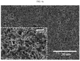
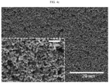
- the SEM images of the separators according to Examples 2-4 and Comparative Example 4 are shown in FIG. 4a , FIG. 4b , FIG. 4c and FIG. 4d , respectively. It can be determined from the SEM images that as the content of PMMA is increased, phase separation of the binder resin composition toward the surface of the separator is deteriorated, and thus the content of the binder resin composition at the surface portion is low. Therefore, it can be seen from the results that an excessively high content of the second binder resin, such as PMMA, may cause degradation of the adhesion.
Landscapes
- Chemical & Material Sciences (AREA)
- Chemical Kinetics & Catalysis (AREA)
- Electrochemistry (AREA)
- General Chemical & Material Sciences (AREA)
- Engineering & Computer Science (AREA)
- Inorganic Chemistry (AREA)
- Materials Engineering (AREA)
- Manufacturing & Machinery (AREA)
- Composite Materials (AREA)
- Cell Separators (AREA)
Applications Claiming Priority (2)
| Application Number | Priority Date | Filing Date | Title |
|---|---|---|---|
| KR20200045488 | 2020-04-14 | ||
| PCT/KR2021/004722 WO2021210922A1 (ko) | 2020-04-14 | 2021-04-14 | 전기화학소자용 분리막 및 이를 제조하는 방법 |
Publications (1)
| Publication Number | Publication Date |
|---|---|
| EP4135113A1 true EP4135113A1 (en) | 2023-02-15 |
Family
ID=78085323
Family Applications (1)
| Application Number | Title | Priority Date | Filing Date |
|---|---|---|---|
| EP21789255.3A Pending EP4135113A1 (en) | 2020-04-14 | 2021-04-14 | Separator for electrochemical device and method for manufacturing same |
Country Status (6)
| Country | Link |
|---|---|
| US (1) | US20230138202A1 (ko) |
| EP (1) | EP4135113A1 (ko) |
| JP (1) | JP7483039B2 (ko) |
| KR (1) | KR20210127643A (ko) |
| CN (1) | CN115398735A (ko) |
| WO (1) | WO2021210922A1 (ko) |
Cited By (1)
| Publication number | Priority date | Publication date | Assignee | Title |
|---|---|---|---|---|
| EP4131623A4 (en) * | 2020-04-06 | 2023-11-22 | LG Energy Solution, Ltd. | ELECTROCHEMICAL ELEMENT SEPARATOR AND METHOD FOR PRODUCING THE SAME |
Families Citing this family (2)
| Publication number | Priority date | Publication date | Assignee | Title |
|---|---|---|---|---|
| KR102558448B1 (ko) * | 2022-06-16 | 2023-07-24 | 주식회사 한솔케미칼 | 분리막용 공중합체 및 이를 포함하는 이차전지 |
| KR20240047634A (ko) * | 2022-10-05 | 2024-04-12 | 주식회사 엘지에너지솔루션 | 전기화학소자용 분리막, 이의 제조방법 및 이를 포함하는 전기화학소자 |
Family Cites Families (15)
| Publication number | Priority date | Publication date | Assignee | Title |
|---|---|---|---|---|
| KR100775310B1 (ko) * | 2004-12-22 | 2007-11-08 | 주식회사 엘지화학 | 유/무기 복합 다공성 분리막 및 이를 이용한 전기 화학소자 |
| RU2015121358A (ru) * | 2012-11-06 | 2016-12-27 | Секисуй Кемикал Ко., Лтд. | Теплостойкая микропористая пленка на основе синтетической смолы, способ ее получения, сепаратор для аккумуляторной батареи с неводным электролитом и аккумуляторная батарея с неводным электролитом |
| WO2015076571A1 (ko) * | 2013-11-21 | 2015-05-28 | 삼성에스디아이 주식회사 | 분리막 코팅제 조성물, 상기 코팅제 조성물로 형성된 분리막 및 이를 이용한 전지 |
| KR102219691B1 (ko) * | 2014-01-13 | 2021-02-24 | 에스케이이노베이션 주식회사 | 내열성 및 전기화학적 안정성이 우수한 세라믹 코팅 세퍼레이터 및 이의 제조방법 |
| JP6378998B2 (ja) | 2014-09-30 | 2018-08-22 | 旭化成株式会社 | 蓄電デバイス用セパレータの製造方法 |
| KR101551757B1 (ko) * | 2014-12-30 | 2015-09-10 | 삼성에스디아이 주식회사 | 다공성 내열층 조성물, 다공성 내열층을 포함하는 분리막, 상기 분리막을 이용한 전기 화학 전지, 및 상기 분리막의 제조 방법 |
| JPWO2017104760A1 (ja) | 2015-12-16 | 2018-10-04 | 積水化学工業株式会社 | 合成樹脂微多孔フィルム及びその製造方法、蓄電デバイス用セパレータ、並びに蓄電デバイス |
| JP6855166B2 (ja) | 2016-01-22 | 2021-04-07 | 旭化成株式会社 | 蓄電デバイス用セパレータ及びその製造方法 |
| JP6334071B1 (ja) | 2016-09-21 | 2018-05-30 | 帝人株式会社 | 非水系二次電池用セパレータ及び非水系二次電池 |
| US10719446B2 (en) | 2017-08-31 | 2020-07-21 | Oracle International Corporation | Directly mapped buffer cache on non-volatile memory |
| KR102263460B1 (ko) * | 2018-01-05 | 2021-06-11 | 주식회사 엘지에너지솔루션 | 유리전이온도가 다른 바인더를 포함하는 분리막 및 이의 제조방법 |
| KR102209826B1 (ko) * | 2018-03-06 | 2021-01-29 | 삼성에스디아이 주식회사 | 분리막, 이의 제조방법 및 이를 포함하는 리튬전지 |
| KR102311810B1 (ko) * | 2018-09-21 | 2021-10-08 | 주식회사 엘지에너지솔루션 | 세퍼레이터 및 이를 포함하는 전기화학소자 |
| KR102437371B1 (ko) * | 2018-09-28 | 2022-08-26 | 주식회사 엘지에너지솔루션 | 전기화학소자용 분리막 및 이를 제조하는 방법 |
| EP4131623A4 (en) | 2020-04-06 | 2023-11-22 | LG Energy Solution, Ltd. | ELECTROCHEMICAL ELEMENT SEPARATOR AND METHOD FOR PRODUCING THE SAME |
-
2021
- 2021-04-14 JP JP2022561610A patent/JP7483039B2/ja active Active
- 2021-04-14 EP EP21789255.3A patent/EP4135113A1/en active Pending
- 2021-04-14 KR KR1020210048821A patent/KR20210127643A/ko unknown
- 2021-04-14 CN CN202180028843.0A patent/CN115398735A/zh active Pending
- 2021-04-14 US US17/918,845 patent/US20230138202A1/en active Pending
- 2021-04-14 WO PCT/KR2021/004722 patent/WO2021210922A1/ko unknown
Cited By (1)
| Publication number | Priority date | Publication date | Assignee | Title |
|---|---|---|---|---|
| EP4131623A4 (en) * | 2020-04-06 | 2023-11-22 | LG Energy Solution, Ltd. | ELECTROCHEMICAL ELEMENT SEPARATOR AND METHOD FOR PRODUCING THE SAME |
Also Published As
| Publication number | Publication date |
|---|---|
| CN115398735A (zh) | 2022-11-25 |
| JP7483039B2 (ja) | 2024-05-14 |
| JP2023521137A (ja) | 2023-05-23 |
| KR20210127643A (ko) | 2021-10-22 |
| WO2021210922A1 (ko) | 2021-10-21 |
| US20230138202A1 (en) | 2023-05-04 |
Similar Documents
| Publication | Publication Date | Title |
|---|---|---|
| KR100758482B1 (ko) | 표면 처리된 다공성 필름 및 이를 이용한 전기 화학 소자 | |
| EP4135113A1 (en) | Separator for electrochemical device and method for manufacturing same | |
| US11990642B2 (en) | Separator for electrochemical device and method for manufacturing the same | |
| EP3916836A1 (en) | Separator for electrochemical device, and electrochemical device comprising same | |
| EP4131623A1 (en) | Separator for electrochemical element and method for manufacturing same | |
| EP4050720A1 (en) | Separator for electrochemical device and electrochemical device comprising same | |
| CN113939949B (zh) | 用于电化学装置的隔板及其制造方法 | |
| EP3958344A1 (en) | Binder resin composition and separator comprising same for electrochemical device | |
| EP3848998A1 (en) | Separator for electrochemical device, and method for producing same | |
| EP4106094A1 (en) | Separator for electrochemical device and production method therefor | |
| KR20210052010A (ko) | 전기화학소자용 분리막 및 이를 포함하는 전기화학소자 | |
| CN115191061B (zh) | 用于电化学装置的隔板及制造该隔板的方法 | |
| CN114730960B (zh) | 用于电化学装置的复合隔板和包括其的电化学装置 | |
| KR102618427B1 (ko) | Si계 음극 활물질을 구비하는 리튬 이차전지 | |
| EP4254636A1 (en) | Separator for electrochemical device, and electrode assembly and electrochemical device comprising same | |
| EP4346001A1 (en) | Separator for lithium secondary battery and lithium secondary battery comprising same | |
| KR20240001083A (ko) | Si계 음극 활물질을 구비하는 리튬 이차전지 | |
| JP2024511266A (ja) | 電気化学素子用分離膜基材、前記基材を含む分離膜、及び電池セル分離膜の形成方法 |
Legal Events
| Date | Code | Title | Description |
|---|---|---|---|
| STAA | Information on the status of an ep patent application or granted ep patent |
Free format text: STATUS: THE INTERNATIONAL PUBLICATION HAS BEEN MADE |
|
| PUAI | Public reference made under article 153(3) epc to a published international application that has entered the european phase |
Free format text: ORIGINAL CODE: 0009012 |
|
| STAA | Information on the status of an ep patent application or granted ep patent |
Free format text: STATUS: REQUEST FOR EXAMINATION WAS MADE |
|
| 17P | Request for examination filed |
Effective date: 20221109 |
|
| AK | Designated contracting states |
Kind code of ref document: A1 Designated state(s): AL AT BE BG CH CY CZ DE DK EE ES FI FR GB GR HR HU IE IS IT LI LT LU LV MC MK MT NL NO PL PT RO RS SE SI SK SM TR |
|
| DAV | Request for validation of the european patent (deleted) | ||
| DAX | Request for extension of the european patent (deleted) |