EP4134551B1 - Deckband und kühlventilatoranordnung damit - Google Patents
Deckband und kühlventilatoranordnung damit Download PDFInfo
- Publication number
- EP4134551B1 EP4134551B1 EP22183592.9A EP22183592A EP4134551B1 EP 4134551 B1 EP4134551 B1 EP 4134551B1 EP 22183592 A EP22183592 A EP 22183592A EP 4134551 B1 EP4134551 B1 EP 4134551B1
- Authority
- EP
- European Patent Office
- Prior art keywords
- rib
- shroud
- slot
- ribs
- slots
- Prior art date
- Legal status (The legal status is an assumption and is not a legal conclusion. Google has not performed a legal analysis and makes no representation as to the accuracy of the status listed.)
- Active
Links
Images



Classifications
-
- F—MECHANICAL ENGINEERING; LIGHTING; HEATING; WEAPONS; BLASTING
- F04—POSITIVE - DISPLACEMENT MACHINES FOR LIQUIDS; PUMPS FOR LIQUIDS OR ELASTIC FLUIDS
- F04D—NON-POSITIVE-DISPLACEMENT PUMPS
- F04D19/00—Axial-flow pumps
- F04D19/002—Axial flow fans
-
- F—MECHANICAL ENGINEERING; LIGHTING; HEATING; WEAPONS; BLASTING
- F04—POSITIVE - DISPLACEMENT MACHINES FOR LIQUIDS; PUMPS FOR LIQUIDS OR ELASTIC FLUIDS
- F04D—NON-POSITIVE-DISPLACEMENT PUMPS
- F04D29/00—Details, component parts, or accessories
- F04D29/40—Casings; Connections of working fluid
- F04D29/52—Casings; Connections of working fluid for axial pumps
- F04D29/54—Fluid-guiding means, e.g. diffusers
- F04D29/541—Specially adapted for elastic fluid pumps
-
- F—MECHANICAL ENGINEERING; LIGHTING; HEATING; WEAPONS; BLASTING
- F04—POSITIVE - DISPLACEMENT MACHINES FOR LIQUIDS; PUMPS FOR LIQUIDS OR ELASTIC FLUIDS
- F04D—NON-POSITIVE-DISPLACEMENT PUMPS
- F04D25/00—Pumping installations or systems
- F04D25/02—Units comprising pumps and their driving means
- F04D25/06—Units comprising pumps and their driving means the pump being electrically driven
-
- F—MECHANICAL ENGINEERING; LIGHTING; HEATING; WEAPONS; BLASTING
- F04—POSITIVE - DISPLACEMENT MACHINES FOR LIQUIDS; PUMPS FOR LIQUIDS OR ELASTIC FLUIDS
- F04D—NON-POSITIVE-DISPLACEMENT PUMPS
- F04D25/00—Pumping installations or systems
- F04D25/02—Units comprising pumps and their driving means
- F04D25/08—Units comprising pumps and their driving means the working fluid being air, e.g. for ventilation
-
- F—MECHANICAL ENGINEERING; LIGHTING; HEATING; WEAPONS; BLASTING
- F04—POSITIVE - DISPLACEMENT MACHINES FOR LIQUIDS; PUMPS FOR LIQUIDS OR ELASTIC FLUIDS
- F04D—NON-POSITIVE-DISPLACEMENT PUMPS
- F04D29/00—Details, component parts, or accessories
- F04D29/40—Casings; Connections of working fluid
- F04D29/52—Casings; Connections of working fluid for axial pumps
- F04D29/522—Casings; Connections of working fluid for axial pumps especially adapted for elastic fluid pumps
-
- F—MECHANICAL ENGINEERING; LIGHTING; HEATING; WEAPONS; BLASTING
- F04—POSITIVE - DISPLACEMENT MACHINES FOR LIQUIDS; PUMPS FOR LIQUIDS OR ELASTIC FLUIDS
- F04D—NON-POSITIVE-DISPLACEMENT PUMPS
- F04D29/00—Details, component parts, or accessories
- F04D29/58—Cooling; Heating; Diminishing heat transfer
- F04D29/582—Cooling; Heating; Diminishing heat transfer specially adapted for elastic fluid pumps
-
- F—MECHANICAL ENGINEERING; LIGHTING; HEATING; WEAPONS; BLASTING
- F04—POSITIVE - DISPLACEMENT MACHINES FOR LIQUIDS; PUMPS FOR LIQUIDS OR ELASTIC FLUIDS
- F04D—NON-POSITIVE-DISPLACEMENT PUMPS
- F04D29/00—Details, component parts, or accessories
- F04D29/60—Mounting; Assembling; Disassembling
- F04D29/601—Mounting; Assembling; Disassembling specially adapted for elastic fluid pumps
- F04D29/602—Mounting in cavities
-
- F—MECHANICAL ENGINEERING; LIGHTING; HEATING; WEAPONS; BLASTING
- F04—POSITIVE - DISPLACEMENT MACHINES FOR LIQUIDS; PUMPS FOR LIQUIDS OR ELASTIC FLUIDS
- F04D—NON-POSITIVE-DISPLACEMENT PUMPS
- F04D29/00—Details, component parts, or accessories
- F04D29/66—Combating cavitation, whirls, noise, vibration or the like; Balancing
- F04D29/661—Combating cavitation, whirls, noise, vibration or the like; Balancing especially adapted for elastic fluid pumps
-
- F—MECHANICAL ENGINEERING; LIGHTING; HEATING; WEAPONS; BLASTING
- F04—POSITIVE - DISPLACEMENT MACHINES FOR LIQUIDS; PUMPS FOR LIQUIDS OR ELASTIC FLUIDS
- F04D—NON-POSITIVE-DISPLACEMENT PUMPS
- F04D29/00—Details, component parts, or accessories
- F04D29/66—Combating cavitation, whirls, noise, vibration or the like; Balancing
- F04D29/661—Combating cavitation, whirls, noise, vibration or the like; Balancing especially adapted for elastic fluid pumps
- F04D29/668—Combating cavitation, whirls, noise, vibration or the like; Balancing especially adapted for elastic fluid pumps damping or preventing mechanical vibrations
-
- F—MECHANICAL ENGINEERING; LIGHTING; HEATING; WEAPONS; BLASTING
- F05—INDEXING SCHEMES RELATING TO ENGINES OR PUMPS IN VARIOUS SUBCLASSES OF CLASSES F01-F04
- F05D—INDEXING SCHEME FOR ASPECTS RELATING TO NON-POSITIVE-DISPLACEMENT MACHINES OR ENGINES, GAS-TURBINES OR JET-PROPULSION PLANTS
- F05D2210/00—Working fluids
- F05D2210/10—Kind or type
- F05D2210/12—Kind or type gaseous, i.e. compressible
Definitions
- This disclosure relates to a shroud and a cooling fan assembly including the shroud for cooling a vehicle engine or a battery.
- the driving force of a vehicle is generated from its engine or driving motor.
- An engine or a battery that supplies power to the driving motor generates a lot of heat.
- cooling of the engine or battery is one of the important factors to increase output efficiency, which may be implemented by a coolant and a radiator.
- the cooling fan assembly serves to lower the temperature of the coolant by introducing outside air into the radiator for cooling an engine or a battery.
- the cooling fan assembly includes a cooling motor, a fan and a shroud.
- the fan is coupled to the cooling motor and rotates to form a cooling airflow.
- the shroud protects the cooling motor and the fan and serves as a connecting member that allows the cooling motor and fan to be coupled to the vehicle.
- Vibration and noise occurring when the cooling fan assembly is driven are one of the challenges to be solved.
- the vibration and noise of the cooling fan assembly are mainly caused by the rotations of the fan and the cooling motor.
- vibration and noise peaks increase.
- a shroud design change may be considered.
- noise generation has been conventionally suppressed by adding or reinforcing members, for example, by increasing the thickness of the shroud.
- the object is to reduce vibration and noise of a cooling fan assembly without adding or reinforcing members in the shroud to solve the previous problems as explained above.
- a shroud according to appended claim 1. Further aspects of such a shroud are defined in the appended claims 2-6 and a cooling fan assembly comprising such a shroud is defined in appended claim 7.
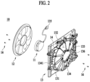
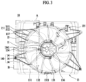
- FIG. 1 , FIG. 2 and FIG. 3 are, respectively, a front perspective view, a dissembled perspective view and a front view of a cooling fan assembly 10 related to the present invention.
- Cooling fan assembly 10 comprises a cooling motor 11, a fan 12 and a shroud 13, and shroud 13 comprises a plenum 131, an opening 132, stators 133, a barrel 134 and ribs 14.
- Plenum 131 constitutes a frame of shroud 13 and is configured to be large enough to cover fan 12.
- Plenum 131 may be provided in a plate shape, and particularly the front surface may include a flat area.
- Opening 132 is formed in a circular shape.
- a bracket 136 for coupling cooling motor 11 and fan 12 to shroud 13 is provided in the center of shroud 13. Cooling motor 11 and fan 12 may be coupled through screws 16, and the combination of cooling motor 11 and fan 12 may also be fixed to bracket 136 through screws 16. Stators 133 allow bracket 136 to be fixed on shroud 13 while securing the area of opening 132. Barrel 134 forms a wall along circumference 1321 of the opening on shroud 13. Barrel 134 as the wall provides an area in which stators 133 can be coupled, protects the side of fan 12 by wrapping it, and guides the airflow formed by fan 12.
- Shroud 13 has preferably a light weight, but should have sufficient stiffness.
- the thin plate-shaped plenum 131 contributes to achieving a light weight of shroud 13, but, on the contrary, is disadvantageous in terms of stiffness.
- Ribs 14 increase the stiffness of this shroud 13.
- Ribs 14 may be walls protruding on plenum 131 in a vertical direction.
- ribs 14 may be configured to connect plenum 131 and barrel 134.
- One end of rib 14 may be connected to one end of stator 133 or provided on the same line such that rib 14 and stator 133 may serve as one frame.
- the plurality of ribs 14 has the advantage of reducing vibration and noise occurring on shroud 13. However it is not necessary to increase stiffness beyond a certain range, and further too many ribs 14 increase the weight of shroud 13. Thus, it is preferable to have an appropriate number of ribs.
- a plurality of ribs 14 may meet at one point to provide an area in which a fastening portion 137 is provided.
- Fastening portion 137 allows shroud 13 to be coupled to the radiator.
- Fastening portion 137 may be in the form of a hole for screw coupling, or may be in the form of a hook for snap-fit coupling.
- the vibration and noise take the form of a wavelength
- the vibration and noise generated from cooling motor 11 and fan 12 are transmitted to barrel 134 and plenum 131 through bracket 136 and stators 133. That is, vibration and noise will radiate outwardly from the center of shroud 13.
- plenum 131 is a thin plate-shaped member, it has low stiffness and is more vulnerable to vibration and noise generation.
- the present invention reduces vibration and noise through slots 15 formed in plenum 131.
- Slots 15 formed in plenum 131 weaken a transmission of the vibration and noise which are caused by fan 12 and cooling motor 11, especially by the cogging torque of cooling motor 11, to the outside through bracket 136 and stators 133.
- the vibration of plenum 131 is reduced by dispersing the cogging torque transmitted from cooling motor 11.
- Slots 15 may be provided anywhere in plenum 131. According to the present invention, a slot is provided along an opening's circumference 1321. Slots 15 which are provided along circumference 1321 of the opening more effectively minimize the transmission of vibration and noise from the center of shroud 13 to plenum 131. That is, plenum 131 is a thin plate-shaped member, and noise and vibration radiate outward from the center of shroud 13, so this may be blocked by slots 15 from the beginning.
- a slot 15 is formed along a part of opening's circumference 1321, and may be provided in a plurality of segmented shapes at an appropriate position and length.
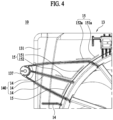
- FIG. 4 illustrates an enlarged view of area A of FIG. 3 .
- slots 15 may be provided between two adjacent ribs 14 or adjacent to the outside of two adjacent ribs 14. Since the area of shroud 13 in which ribs 14 are provided has relatively high stiffness, even if slots 15 slightly decrease the stiffness, the area of shroud 13 having ribs 14 and slots 15 may maintain appropriate stiffness.
- Plenum 131 may be made of plastic, and in this case, plenum 131 may be injection molded by a mold. When plenum 131 is injection molded by a mold, slots 15 may also be formed together by the mold. Since the protrusions corresponding to slots 15 are included in the mold for forming plenum 131, slots 15 may be formed without a separate slot forming process. It is preferable for slots 15 to have a thinner width, but when slots 15 are molded through a mold process, the width is preferably 1 mm or more in order to secure the shape reliability of slots 15. Preferably, the width of slots 15 may be 1mm to 3mm, and in particular 2mm.
- Slot 15 is formed along opening's circumference 1321 and is defined as an arc slot 151.
- slot 15 is formed along rib 14 and is thus defined as a rib slot 152.
- Slots 15 are preferably formed to be about 5mm apart from opening 132 (more specifically, from barrel 134 from a design point of view) or ribs 14. That is, since barrel 134 forms the boundary of opening 132, slots 15 formed along opening's circumference 1321 may be treated as being formed along circumference 1341 of the barrel, and it may be understood that keeping a certain distance from circumference 1321 of the opening is to keep a certain distance from circumference 1341 of the barrel.
- One slot 15 may be configured to have arc slot 151 only, or rib slot 152 only. According to the present invention, a slot 15 is configured to have arc slot 151 and rib slot 152 together.
- a slot 15 including both arc slot 151 and rib slot 152
- one end of arc slot 151 and one end of rib slot 152 are connected to each other, and the other end of arc slot 151 is thus not connected to rib slot 152. This is to prevent the stiffness of shroud 13 from being excessively deteriorated by slots 15 being excessively provided in adjacent areas.
- Rib slot 152 provided between adjacent two ribs 14 may be provided on a side having a larger angle among two sides made by intersection of rib 14 and opening's circumference 1321. This is because the effect of reinforcing stiffness by ribs 14 is less in the side having a larger angle than in the other side having a smaller angle, and thus, vibration and noise are more likely to occur in the side of a larger angle. That is, arc slot 151 and rib slot 152 provided between two adjacent ribs 14 may form an obtuse angle. In addition, arc slot 151a and rib slot 152a provided adjacent to the outside of two adjacent ribs 14 may also form an obtuse angle. On the other hand, like rib group 140 located at the lower right of FIG. 3 , when the difference between the two angles created by one rib 14 and opening's circumference 1321 is small, arc slot 151 and rib slot 152 may be connected at a right angle or an acute angle close to a right angle.
- FIG. 5 illustrates a partial view of a shroud 13 according to an embodiment of the slots which is not according to the present invention.
- arc slot 151 and rib slot 152 are provided as separate slots 15 rather than in one slot 15 between two adjacent ribs 14 or adjacent to the outside of the two adjacent ribs 14. This means that arc slot 151 and rib slot 152 are provided to be spaced apart.
- the feature that arc slot 151 and rib slot 152 are spaced apart from each other has advantage for the stiffness of plenum 131.
- FIG. 6 illustrates an enlarged view of area B of FIG. 3 .
- margin area 153 may be formed such that the other end of arc slot 151 does not extend to another adjacent rib 14 and may maintain an appropriate distance with adjacent rib 14 to keep an appropriate stiffness of shroud 13.
- margin area 153 may be formed in the vicinity of at least some of arc slots 151 of the plurality of slots 15 provided between two adjacent ribs 14, wherein one end of arc slot 151 and one end of rib slot 152 are connected to each other.
- Rib group 140 consists of at least two ribs 14 configured to be adjacent to each other, and in particular, may consist of three ribs 14. In one rib group 140, ribs 14 may be gathered at one point where fastening portion 137 may be positioned.
- rib group 140 may be located in four areas of upper left, lower left, upper right, and lower right of shroud 13 as shown in FIG. 3 .
- the total length of the plurality of slots 15 corresponding to each rib group 140 may be longer as the size of rib group 140 is larger .
- the size means the area on plenum 131 occupied by rib group 140. That is, between two rib groups 140, if a size of a first rib group 140 is bigger than a size of a second rib group 140, a total length of slots 15 formed corresponding to first rib group 140 is longer than a total length of slots 15 formed corresponding to second rib group 140.
- the larger rib group 140 may mean that the area of plenum 131 corresponding to rib group 140 is larger.
- the larger area of plenum 131 has a greater need to reduce vibration and noise through more or longer slots 15.
- Motor electrical connector 135 may be attached to or around at least one of the plurality of rib groups 140.
- the stiffness of the relevant area may be reinforced by the attachment of motor connector 135, and therefore, vibration and noise reducing effects may be achieved without slots 15. Accordingly, slots 15 corresponding to rib group 140 on the side where motor connector 135 is provided may be omitted.
- slots 15 may be equally applied even when any structure, other than motor connector 135, is attached to increase the stiffness according to embodiments.
- Rib group 140 of the area where the structure such as motor connector 135 is attached but slots 15 are not provided may be partly supplemented by slots 15 of another adjacent rib group 140.
- motor connector 135 is provided on the upper right, and thus four slots 15 may be provided to rib group 140 on the lower right while three slots 15 may be provided to each rib group 140 on the upper left and lower left.
- FIG. 7 illustrates frequency (Hz) - noise (dB) graphs according to a certain number of revolutions of the cooling fan assembly related to the present invention.
- the left graph is a test result of the cooling fan assembly without slots
- the right graph is a test result of the cooling fan assembly with the slots.
- Duty corresponds to the speed of rotation of the fan. For example, Duty 25% may correspond to about 875 rpm, and Duty 90% to about 2500 rpm.
- the graphs of FIG. 7 show the results of the case where the mean Duty is 45% corresponding to approximately 1325 rpm.
- the noise level is relatively high compared to surrounding noise levels.
- the frequency corresponding to the at least one point is defined as the resonance frequency band of the cooling fan assembly.
- the noise of the right graph for the case where slots are provided is reduced compared to that of the left graph for the case where slots are not provided.
- Point A and Point B where the noise level is much higher than the surroundings, it can be found that the noise is significantly reduced.
- FIG. 7 has graphs showing the results of the case where the mean Duty is 45%. It was confirmed that the technical effect of a similar trend was obtained in the cases of having different Duty values, which can be also found in FIG. 8 .
- FIG. 8 is a duty (%) - noise (dBA) graph of the cooling fan assembly related to the present invention.
- FIG. 8 is a test result of measuring noise while maintaining the number of revolutions of the cooling fan assembly for a predetermined time, for example, 10 seconds.
- '600W Base' indicates a case where there is no slot
- '600W Slot' indicates a case where there is a slot.
- the noise is reduced when the slot is provided, and in particular, the noise is reduced by 5dBA or more at 35% Duty.
Landscapes
- Engineering & Computer Science (AREA)
- Mechanical Engineering (AREA)
- General Engineering & Computer Science (AREA)
- Physics & Mathematics (AREA)
- Thermal Sciences (AREA)
- Motor Or Generator Frames (AREA)
- Motor Or Generator Cooling System (AREA)
- Structures Of Non-Positive Displacement Pumps (AREA)
Claims (7)
- Abdeckung (13), die ein Plenum (131) und eine Öffnung (132) zum Sichern eines Bereichs für eine Luftströmung durch Drehung eines Axialgebläses (12) umfasst, wobei das Plenum (131) einen Rahmen der Abdeckung (13) bildet und ausreichend groß ausgelegt ist, um das Gebläse (12) abzudecken, wobei die Abdeckung (13) ferner einen Schlitz (15) umfasst, der auf dem Plenum (131) gebildet ist, und wobei die Öffnung (132) in einer Kreisform bereitgestellt ist und der Schlitz (15) einen Bogenschlitz (151) umfasst, der entlang eines Teils eines Umfangs (1321) der Öffnung (132) gebildet ist, und wobei die Abdeckung (13) ferner eine Rippe (14) umfasst, die auf dem Plenum (131) gebildet ist, und der Schlitz (15) ferner einen Rippenschlitz (152) umfasst, der entlang der Rippe (14) gebildet ist, dadurch gekennzeichnet, dass der Schlitz (15) den Bogenschlitz (151) und den Rippenschlitz (152) umfasst, so dass ein Ende des Bogenschlitzes (151) mit einem Ende des Rippenschlitzes (152) verbunden ist.
- Abdeckung (13) nach Anspruch 1, wobei der Schlitz (15) zwischen zwei benachbarten Rippen (14) oder benachbart zu einer Außenseite der zwei benachbarten Rippen (14) bereitgestellt ist.
- Abdeckung (13) nach Anspruch 1, wobei der Bogenschlitz (151) und der Rippenschlitz (152) in einem spitzen Winkel, der beinahe einem rechten Winkel entspricht, in einem rechten Winkel oder in einem stumpfen Winkel miteinander verbunden sind.
- Abdeckung (13) nach Anspruch 1, wobei eine Mehrzahl von Rippen (14) eine Rippengruppe (140) bildet, wobei sich die Mehrzahl von Rippen (14) an einem Punkt trifft;wobei eine Mehrzahl der Rippengruppen (140) in der Abdeckung (13) bereitgestellt ist; undwobei, wenn eine Größe einer ersten Rippengruppe (140) größer als eine Größe einer zweiten Rippengruppe (140) ist, eine Gesamtlänge der Schlitze (15), die entsprechend der ersten Rippengruppe (140) gebildet sind, länger ist als eine Gesamtlänge der Schlitze (15), die entsprechend der zweiten Rippengruppe (140) gebildet sind, wobei die Größe den Bereich auf dem Plenum (131) bezeichnet, der von der Rippengruppe (140) eingenommen wird.
- Abdeckung (13) nach Anspruch 1, wobei eine Mehrzahl der Rippen (14) eine Rippengruppe (140) bildet, wobei sich die Rippen (14) an einem Punkt treffen;wobei eine Mehrzahl der Rippengruppen (140) in der Abdeckung (13) bereitgestellt ist, und ein elektrischer Motorverbinder (135) an oder um eine der Rippengruppen (140) herum angebracht ist; undwobei der Schlitz 15 nicht an der einen der Rippengruppen (140) bereitgestellt ist.
- Abdeckung (13) nach Anspruch 1, wobei der Bogenschlitz (151) und der Rippenschlitz (152) zwischen einer ersten Rippe (14) und einer zweiten Rippe (14) angeordnet sind, und die Schlitze (151, 152) nahe der ersten Rippe (14) miteinander verbunden sind; und
wobei die Abdeckung (13) ferner einen Randbereich (153) umfasst, so dass sich der Bogenschlitz (151) nicht zu der zweiten Rippe (14) erstreckt und einen vorbestimmten Abstand von der zweiten Rippe (14) beibehält. - Kühlgebläseanordnung (10), die die Abdeckung (13) nach einem der Ansprüche 1 bis 6, einen Kühlmotor (11) und ein Gebläse (12) umfasst, das mit der Abdeckung (13) gekoppelt ist.
Applications Claiming Priority (1)
| Application Number | Priority Date | Filing Date | Title |
|---|---|---|---|
| KR1020210104723A KR20230022677A (ko) | 2021-08-09 | 2021-08-09 | 쉬라우드 및 쉬라우드를 포함하는 쿨링팬 어셈블리 |
Publications (2)
| Publication Number | Publication Date |
|---|---|
| EP4134551A1 EP4134551A1 (de) | 2023-02-15 |
| EP4134551B1 true EP4134551B1 (de) | 2025-06-11 |
Family
ID=82404372
Family Applications (1)
| Application Number | Title | Priority Date | Filing Date |
|---|---|---|---|
| EP22183592.9A Active EP4134551B1 (de) | 2021-08-09 | 2022-07-07 | Deckband und kühlventilatoranordnung damit |
Country Status (2)
| Country | Link |
|---|---|
| EP (1) | EP4134551B1 (de) |
| KR (1) | KR20230022677A (de) |
Family Cites Families (2)
| Publication number | Priority date | Publication date | Assignee | Title |
|---|---|---|---|---|
| US10041505B2 (en) * | 2011-06-14 | 2018-08-07 | Robert Bosch Llc | Airflow assembly having improved acoustical performance |
| ITTO20140004U1 (it) * | 2014-01-10 | 2015-07-10 | Johnson Electric Asti S R L | Ventola per un elettroventilatore di raffreddamento, particolarmente per uno scambiatore di calore per un autoveicolo |
-
2021
- 2021-08-09 KR KR1020210104723A patent/KR20230022677A/ko active Pending
-
2022
- 2022-07-07 EP EP22183592.9A patent/EP4134551B1/de active Active
Also Published As
| Publication number | Publication date |
|---|---|
| EP4134551A1 (de) | 2023-02-15 |
| KR20230022677A (ko) | 2023-02-16 |
Similar Documents
| Publication | Publication Date | Title |
|---|---|---|
| US5755557A (en) | Axial flow fan | |
| EP1290349B1 (de) | Kühlventilator mit trichterförmigem mantel und entsprechender blattform | |
| US5180279A (en) | Heat shield and deflector for engine cooling fan motor | |
| JP5072506B2 (ja) | ファンモータ | |
| CN100400894C (zh) | 带有重叠风扇的发动机冷却风扇组件 | |
| US20040223845A1 (en) | Automotive engine-cooling fan assembly | |
| EP1800009B1 (de) | Lüfter | |
| JPH07194059A (ja) | 車両用交流発電機の冷却用ファン | |
| US11951797B2 (en) | Cooling pack assembly | |
| WO2012162650A1 (en) | Fan duct with downstream edge shaped for noise reduction | |
| WO2012174283A2 (en) | Airflow assembly having improved acoustical performance | |
| EP2000645A2 (de) | Kühlstruktur für arbeitsfahrzeug | |
| JP4586364B2 (ja) | ラジエータ冷却ファン取付構造 | |
| CN114576180A (zh) | 反向旋转风扇组件 | |
| US20200014282A1 (en) | Cooling module with axial fan for vehicles, especially for electric vehicles | |
| EP4134551A1 (de) | Deckband und kühlventilatoranordnung damit | |
| EP0733809A1 (de) | Stützträger | |
| KR102335896B1 (ko) | 모터 냉각용 공기 흐름 구조가 개선된 냉각팬 슈라우드 장치 | |
| US20220299045A1 (en) | Fan hub isolator | |
| CN103133412A (zh) | 风扇模块 | |
| KR102190928B1 (ko) | 구동유닛 및 이를 포함하는 쿨링장치 | |
| KR102878447B1 (ko) | 고주파 소음 저감과 생산성 확보를 위한 팬 | |
| JP2002354751A (ja) | 電動機 | |
| KR200325417Y1 (ko) | 비틀림 없는 팬허브를 구비한 자동차 엔진냉각팬 조립체 | |
| EP4285471B1 (de) | Endkappe für elektromotoren und motoreinheit mit einem mit der endkappe verbundenen elektromotor |
Legal Events
| Date | Code | Title | Description |
|---|---|---|---|
| PUAI | Public reference made under article 153(3) epc to a published international application that has entered the european phase |
Free format text: ORIGINAL CODE: 0009012 |
|
| STAA | Information on the status of an ep patent application or granted ep patent |
Free format text: STATUS: THE APPLICATION HAS BEEN PUBLISHED |
|
| AK | Designated contracting states |
Kind code of ref document: A1 Designated state(s): AL AT BE BG CH CY CZ DE DK EE ES FI FR GB GR HR HU IE IS IT LI LT LU LV MC MK MT NL NO PL PT RO RS SE SI SK SM TR |
|
| STAA | Information on the status of an ep patent application or granted ep patent |
Free format text: STATUS: REQUEST FOR EXAMINATION WAS MADE |
|
| 17P | Request for examination filed |
Effective date: 20230816 |
|
| RBV | Designated contracting states (corrected) |
Designated state(s): AL AT BE BG CH CY CZ DE DK EE ES FI FR GB GR HR HU IE IS IT LI LT LU LV MC MK MT NL NO PL PT RO RS SE SI SK SM TR |
|
| GRAP | Despatch of communication of intention to grant a patent |
Free format text: ORIGINAL CODE: EPIDOSNIGR1 |
|
| STAA | Information on the status of an ep patent application or granted ep patent |
Free format text: STATUS: GRANT OF PATENT IS INTENDED |
|
| INTG | Intention to grant announced |
Effective date: 20250121 |
|
| GRAS | Grant fee paid |
Free format text: ORIGINAL CODE: EPIDOSNIGR3 |
|
| GRAA | (expected) grant |
Free format text: ORIGINAL CODE: 0009210 |
|
| STAA | Information on the status of an ep patent application or granted ep patent |
Free format text: STATUS: THE PATENT HAS BEEN GRANTED |
|
| AK | Designated contracting states |
Kind code of ref document: B1 Designated state(s): AL AT BE BG CH CY CZ DE DK EE ES FI FR GB GR HR HU IE IS IT LI LT LU LV MC MK MT NL NO PL PT RO RS SE SI SK SM TR |
|
| REG | Reference to a national code |
Ref country code: GB Ref legal event code: FG4D |
|
| REG | Reference to a national code |
Ref country code: CH Ref legal event code: EP |
|
| REG | Reference to a national code |
Ref country code: IE Ref legal event code: FG4D |
|
| REG | Reference to a national code |
Ref country code: DE Ref legal event code: R096 Ref document number: 602022015735 Country of ref document: DE |
|
| PG25 | Lapsed in a contracting state [announced via postgrant information from national office to epo] |
Ref country code: ES Free format text: LAPSE BECAUSE OF FAILURE TO SUBMIT A TRANSLATION OF THE DESCRIPTION OR TO PAY THE FEE WITHIN THE PRESCRIBED TIME-LIMIT Effective date: 20250611 Ref country code: FI Free format text: LAPSE BECAUSE OF FAILURE TO SUBMIT A TRANSLATION OF THE DESCRIPTION OR TO PAY THE FEE WITHIN THE PRESCRIBED TIME-LIMIT Effective date: 20250611 |
|
| PGFP | Annual fee paid to national office [announced via postgrant information from national office to epo] |
Ref country code: DE Payment date: 20250924 Year of fee payment: 4 |
|
| REG | Reference to a national code |
Ref country code: LT Ref legal event code: MG9D |
|
| PG25 | Lapsed in a contracting state [announced via postgrant information from national office to epo] |
Ref country code: NO Free format text: LAPSE BECAUSE OF FAILURE TO SUBMIT A TRANSLATION OF THE DESCRIPTION OR TO PAY THE FEE WITHIN THE PRESCRIBED TIME-LIMIT Effective date: 20250911 Ref country code: GR Free format text: LAPSE BECAUSE OF FAILURE TO SUBMIT A TRANSLATION OF THE DESCRIPTION OR TO PAY THE FEE WITHIN THE PRESCRIBED TIME-LIMIT Effective date: 20250912 |
|
| REG | Reference to a national code |
Ref country code: NL Ref legal event code: MP Effective date: 20250611 |
|
| PG25 | Lapsed in a contracting state [announced via postgrant information from national office to epo] |
Ref country code: BG Free format text: LAPSE BECAUSE OF FAILURE TO SUBMIT A TRANSLATION OF THE DESCRIPTION OR TO PAY THE FEE WITHIN THE PRESCRIBED TIME-LIMIT Effective date: 20250611 |
|
| PG25 | Lapsed in a contracting state [announced via postgrant information from national office to epo] |
Ref country code: HR Free format text: LAPSE BECAUSE OF FAILURE TO SUBMIT A TRANSLATION OF THE DESCRIPTION OR TO PAY THE FEE WITHIN THE PRESCRIBED TIME-LIMIT Effective date: 20250611 |
|
| PGFP | Annual fee paid to national office [announced via postgrant information from national office to epo] |
Ref country code: AT Payment date: 20251020 Year of fee payment: 4 |
|
| PG25 | Lapsed in a contracting state [announced via postgrant information from national office to epo] |
Ref country code: RS Free format text: LAPSE BECAUSE OF FAILURE TO SUBMIT A TRANSLATION OF THE DESCRIPTION OR TO PAY THE FEE WITHIN THE PRESCRIBED TIME-LIMIT Effective date: 20250911 |
|
| PG25 | Lapsed in a contracting state [announced via postgrant information from national office to epo] |
Ref country code: LV Free format text: LAPSE BECAUSE OF FAILURE TO SUBMIT A TRANSLATION OF THE DESCRIPTION OR TO PAY THE FEE WITHIN THE PRESCRIBED TIME-LIMIT Effective date: 20250611 |
|
| PG25 | Lapsed in a contracting state [announced via postgrant information from national office to epo] |
Ref country code: NL Free format text: LAPSE BECAUSE OF FAILURE TO SUBMIT A TRANSLATION OF THE DESCRIPTION OR TO PAY THE FEE WITHIN THE PRESCRIBED TIME-LIMIT Effective date: 20250611 |
|
| PG25 | Lapsed in a contracting state [announced via postgrant information from national office to epo] |
Ref country code: PT Free format text: LAPSE BECAUSE OF FAILURE TO SUBMIT A TRANSLATION OF THE DESCRIPTION OR TO PAY THE FEE WITHIN THE PRESCRIBED TIME-LIMIT Effective date: 20251013 |
|
| REG | Reference to a national code |
Ref country code: AT Ref legal event code: MK05 Ref document number: 1802464 Country of ref document: AT Kind code of ref document: T Effective date: 20250611 |
|
| PG25 | Lapsed in a contracting state [announced via postgrant information from national office to epo] |
Ref country code: IS Free format text: LAPSE BECAUSE OF FAILURE TO SUBMIT A TRANSLATION OF THE DESCRIPTION OR TO PAY THE FEE WITHIN THE PRESCRIBED TIME-LIMIT Effective date: 20251011 |
|
| PG25 | Lapsed in a contracting state [announced via postgrant information from national office to epo] |
Ref country code: AT Free format text: LAPSE BECAUSE OF FAILURE TO SUBMIT A TRANSLATION OF THE DESCRIPTION OR TO PAY THE FEE WITHIN THE PRESCRIBED TIME-LIMIT Effective date: 20250611 Ref country code: SM Free format text: LAPSE BECAUSE OF FAILURE TO SUBMIT A TRANSLATION OF THE DESCRIPTION OR TO PAY THE FEE WITHIN THE PRESCRIBED TIME-LIMIT Effective date: 20250611 |
|
| PG25 | Lapsed in a contracting state [announced via postgrant information from national office to epo] |
Ref country code: CZ Free format text: LAPSE BECAUSE OF FAILURE TO SUBMIT A TRANSLATION OF THE DESCRIPTION OR TO PAY THE FEE WITHIN THE PRESCRIBED TIME-LIMIT Effective date: 20250611 |
|
| PG25 | Lapsed in a contracting state [announced via postgrant information from national office to epo] |
Ref country code: PL Free format text: LAPSE BECAUSE OF FAILURE TO SUBMIT A TRANSLATION OF THE DESCRIPTION OR TO PAY THE FEE WITHIN THE PRESCRIBED TIME-LIMIT Effective date: 20250611 |
|
| PG25 | Lapsed in a contracting state [announced via postgrant information from national office to epo] |
Ref country code: EE Free format text: LAPSE BECAUSE OF FAILURE TO SUBMIT A TRANSLATION OF THE DESCRIPTION OR TO PAY THE FEE WITHIN THE PRESCRIBED TIME-LIMIT Effective date: 20250611 |
|
| PG25 | Lapsed in a contracting state [announced via postgrant information from national office to epo] |
Ref country code: SK Free format text: LAPSE BECAUSE OF FAILURE TO SUBMIT A TRANSLATION OF THE DESCRIPTION OR TO PAY THE FEE WITHIN THE PRESCRIBED TIME-LIMIT Effective date: 20250611 |
|
| PG25 | Lapsed in a contracting state [announced via postgrant information from national office to epo] |
Ref country code: RO Free format text: LAPSE BECAUSE OF FAILURE TO SUBMIT A TRANSLATION OF THE DESCRIPTION OR TO PAY THE FEE WITHIN THE PRESCRIBED TIME-LIMIT Effective date: 20250611 |
|
| REG | Reference to a national code |
Ref country code: CH Ref legal event code: H13 Free format text: ST27 STATUS EVENT CODE: U-0-0-H10-H13 (AS PROVIDED BY THE NATIONAL OFFICE) Effective date: 20260224 |
|
| REG | Reference to a national code |
Ref country code: DE Ref legal event code: R097 Ref document number: 602022015735 Country of ref document: DE |
|
| PG25 | Lapsed in a contracting state [announced via postgrant information from national office to epo] |
Ref country code: LU Free format text: LAPSE BECAUSE OF NON-PAYMENT OF DUE FEES Effective date: 20250707 |
|
| REG | Reference to a national code |
Ref country code: BE Ref legal event code: MM Effective date: 20250731 |
|
| PG25 | Lapsed in a contracting state [announced via postgrant information from national office to epo] |
Ref country code: MC Free format text: LAPSE BECAUSE OF FAILURE TO SUBMIT A TRANSLATION OF THE DESCRIPTION OR TO PAY THE FEE WITHIN THE PRESCRIBED TIME-LIMIT Effective date: 20250611 |
|
| PG25 | Lapsed in a contracting state [announced via postgrant information from national office to epo] |
Ref country code: DK Free format text: LAPSE BECAUSE OF FAILURE TO SUBMIT A TRANSLATION OF THE DESCRIPTION OR TO PAY THE FEE WITHIN THE PRESCRIBED TIME-LIMIT Effective date: 20250611 |
|
| PG25 | Lapsed in a contracting state [announced via postgrant information from national office to epo] |
Ref country code: BE Free format text: LAPSE BECAUSE OF NON-PAYMENT OF DUE FEES Effective date: 20250731 Ref country code: IT Free format text: LAPSE BECAUSE OF FAILURE TO SUBMIT A TRANSLATION OF THE DESCRIPTION OR TO PAY THE FEE WITHIN THE PRESCRIBED TIME-LIMIT Effective date: 20250611 |
|
| PLBE | No opposition filed within time limit |
Free format text: ORIGINAL CODE: 0009261 |
|
| STAA | Information on the status of an ep patent application or granted ep patent |
Free format text: STATUS: NO OPPOSITION FILED WITHIN TIME LIMIT |
|
| PG25 | Lapsed in a contracting state [announced via postgrant information from national office to epo] |
Ref country code: CH Free format text: LAPSE BECAUSE OF NON-PAYMENT OF DUE FEES Effective date: 20250731 |
|
| REG | Reference to a national code |
Ref country code: CH Ref legal event code: L10 Free format text: ST27 STATUS EVENT CODE: U-0-0-L10-L00 (AS PROVIDED BY THE NATIONAL OFFICE) Effective date: 20260423 |