EP4134549A1 - Schraubenverdichter, kühlsystem und verfahren zur steuerung des kühlsystems - Google Patents
Schraubenverdichter, kühlsystem und verfahren zur steuerung des kühlsystems Download PDFInfo
- Publication number
- EP4134549A1 EP4134549A1 EP21785574.1A EP21785574A EP4134549A1 EP 4134549 A1 EP4134549 A1 EP 4134549A1 EP 21785574 A EP21785574 A EP 21785574A EP 4134549 A1 EP4134549 A1 EP 4134549A1
- Authority
- EP
- European Patent Office
- Prior art keywords
- adjustment
- screw compressor
- silencing
- channel
- discharge cavity
- Prior art date
- Legal status (The legal status is an assumption and is not a legal conclusion. Google has not performed a legal analysis and makes no representation as to the accuracy of the status listed.)
- Granted
Links
Images







Classifications
-
- F—MECHANICAL ENGINEERING; LIGHTING; HEATING; WEAPONS; BLASTING
- F04—POSITIVE - DISPLACEMENT MACHINES FOR LIQUIDS; PUMPS FOR LIQUIDS OR ELASTIC FLUIDS
- F04C—ROTARY-PISTON, OR OSCILLATING-PISTON, POSITIVE-DISPLACEMENT MACHINES FOR LIQUIDS; ROTARY-PISTON, OR OSCILLATING-PISTON, POSITIVE-DISPLACEMENT PUMPS
- F04C29/00—Component parts, details or accessories of pumps or pumping installations, not provided for in groups F04C18/00 - F04C28/00
- F04C29/06—Silencing
- F04C29/065—Noise dampening volumes, e.g. muffler chambers
-
- F—MECHANICAL ENGINEERING; LIGHTING; HEATING; WEAPONS; BLASTING
- F04—POSITIVE - DISPLACEMENT MACHINES FOR LIQUIDS; PUMPS FOR LIQUIDS OR ELASTIC FLUIDS
- F04C—ROTARY-PISTON, OR OSCILLATING-PISTON, POSITIVE-DISPLACEMENT MACHINES FOR LIQUIDS; ROTARY-PISTON, OR OSCILLATING-PISTON, POSITIVE-DISPLACEMENT PUMPS
- F04C18/00—Rotary-piston pumps specially adapted for elastic fluids
- F04C18/08—Rotary-piston pumps specially adapted for elastic fluids of intermeshing-engagement type, i.e. with engagement of co-operating members similar to that of toothed gearing
- F04C18/082—Details specially related to intermeshing engagement type pumps
- F04C18/086—Carter
-
- F—MECHANICAL ENGINEERING; LIGHTING; HEATING; WEAPONS; BLASTING
- F04—POSITIVE - DISPLACEMENT MACHINES FOR LIQUIDS; PUMPS FOR LIQUIDS OR ELASTIC FLUIDS
- F04C—ROTARY-PISTON, OR OSCILLATING-PISTON, POSITIVE-DISPLACEMENT MACHINES FOR LIQUIDS; ROTARY-PISTON, OR OSCILLATING-PISTON, POSITIVE-DISPLACEMENT PUMPS
- F04C18/00—Rotary-piston pumps specially adapted for elastic fluids
- F04C18/08—Rotary-piston pumps specially adapted for elastic fluids of intermeshing-engagement type, i.e. with engagement of co-operating members similar to that of toothed gearing
- F04C18/12—Rotary-piston pumps specially adapted for elastic fluids of intermeshing-engagement type, i.e. with engagement of co-operating members similar to that of toothed gearing of other than internal-axis type
- F04C18/14—Rotary-piston pumps specially adapted for elastic fluids of intermeshing-engagement type, i.e. with engagement of co-operating members similar to that of toothed gearing of other than internal-axis type with toothed rotary pistons
- F04C18/16—Rotary-piston pumps specially adapted for elastic fluids of intermeshing-engagement type, i.e. with engagement of co-operating members similar to that of toothed gearing of other than internal-axis type with toothed rotary pistons with helical teeth, e.g. chevron-shaped, screw type
-
- F—MECHANICAL ENGINEERING; LIGHTING; HEATING; WEAPONS; BLASTING
- F04—POSITIVE - DISPLACEMENT MACHINES FOR LIQUIDS; PUMPS FOR LIQUIDS OR ELASTIC FLUIDS
- F04C—ROTARY-PISTON, OR OSCILLATING-PISTON, POSITIVE-DISPLACEMENT MACHINES FOR LIQUIDS; ROTARY-PISTON, OR OSCILLATING-PISTON, POSITIVE-DISPLACEMENT PUMPS
- F04C23/00—Combinations of two or more pumps, each being of rotary-piston or oscillating-piston type, specially adapted for elastic fluids; Pumping installations specially adapted for elastic fluids; Multi-stage pumps specially adapted for elastic fluids
- F04C23/02—Pumps characterised by combination with, or adaptation to, specific driving engines or motors
-
- F—MECHANICAL ENGINEERING; LIGHTING; HEATING; WEAPONS; BLASTING
- F04—POSITIVE - DISPLACEMENT MACHINES FOR LIQUIDS; PUMPS FOR LIQUIDS OR ELASTIC FLUIDS
- F04C—ROTARY-PISTON, OR OSCILLATING-PISTON, POSITIVE-DISPLACEMENT MACHINES FOR LIQUIDS; ROTARY-PISTON, OR OSCILLATING-PISTON, POSITIVE-DISPLACEMENT PUMPS
- F04C28/00—Control of, monitoring of, or safety arrangements for, pumps or pumping installations specially adapted for elastic fluids
- F04C28/28—Safety arrangements; Monitoring
-
- F—MECHANICAL ENGINEERING; LIGHTING; HEATING; WEAPONS; BLASTING
- F04—POSITIVE - DISPLACEMENT MACHINES FOR LIQUIDS; PUMPS FOR LIQUIDS OR ELASTIC FLUIDS
- F04C—ROTARY-PISTON, OR OSCILLATING-PISTON, POSITIVE-DISPLACEMENT MACHINES FOR LIQUIDS; ROTARY-PISTON, OR OSCILLATING-PISTON, POSITIVE-DISPLACEMENT PUMPS
- F04C29/00—Component parts, details or accessories of pumps or pumping installations, not provided for in groups F04C18/00 - F04C28/00
-
- F—MECHANICAL ENGINEERING; LIGHTING; HEATING; WEAPONS; BLASTING
- F04—POSITIVE - DISPLACEMENT MACHINES FOR LIQUIDS; PUMPS FOR LIQUIDS OR ELASTIC FLUIDS
- F04C—ROTARY-PISTON, OR OSCILLATING-PISTON, POSITIVE-DISPLACEMENT MACHINES FOR LIQUIDS; ROTARY-PISTON, OR OSCILLATING-PISTON, POSITIVE-DISPLACEMENT PUMPS
- F04C29/00—Component parts, details or accessories of pumps or pumping installations, not provided for in groups F04C18/00 - F04C28/00
- F04C29/06—Silencing
-
- F—MECHANICAL ENGINEERING; LIGHTING; HEATING; WEAPONS; BLASTING
- F04—POSITIVE - DISPLACEMENT MACHINES FOR LIQUIDS; PUMPS FOR LIQUIDS OR ELASTIC FLUIDS
- F04C—ROTARY-PISTON, OR OSCILLATING-PISTON, POSITIVE-DISPLACEMENT MACHINES FOR LIQUIDS; ROTARY-PISTON, OR OSCILLATING-PISTON, POSITIVE-DISPLACEMENT PUMPS
- F04C29/00—Component parts, details or accessories of pumps or pumping installations, not provided for in groups F04C18/00 - F04C28/00
- F04C29/06—Silencing
- F04C29/061—Silencers using overlapping frequencies, e.g. Helmholtz resonators
-
- F—MECHANICAL ENGINEERING; LIGHTING; HEATING; WEAPONS; BLASTING
- F04—POSITIVE - DISPLACEMENT MACHINES FOR LIQUIDS; PUMPS FOR LIQUIDS OR ELASTIC FLUIDS
- F04C—ROTARY-PISTON, OR OSCILLATING-PISTON, POSITIVE-DISPLACEMENT MACHINES FOR LIQUIDS; ROTARY-PISTON, OR OSCILLATING-PISTON, POSITIVE-DISPLACEMENT PUMPS
- F04C29/00—Component parts, details or accessories of pumps or pumping installations, not provided for in groups F04C18/00 - F04C28/00
- F04C29/06—Silencing
- F04C29/068—Silencing the silencing means being arranged inside the pump housing
-
- F—MECHANICAL ENGINEERING; LIGHTING; HEATING; WEAPONS; BLASTING
- F04—POSITIVE - DISPLACEMENT MACHINES FOR LIQUIDS; PUMPS FOR LIQUIDS OR ELASTIC FLUIDS
- F04C—ROTARY-PISTON, OR OSCILLATING-PISTON, POSITIVE-DISPLACEMENT MACHINES FOR LIQUIDS; ROTARY-PISTON, OR OSCILLATING-PISTON, POSITIVE-DISPLACEMENT PUMPS
- F04C29/00—Component parts, details or accessories of pumps or pumping installations, not provided for in groups F04C18/00 - F04C28/00
- F04C29/12—Arrangements for admission or discharge of the working fluid, e.g. constructional features of the inlet or outlet
-
- F—MECHANICAL ENGINEERING; LIGHTING; HEATING; WEAPONS; BLASTING
- F25—REFRIGERATION OR COOLING; COMBINED HEATING AND REFRIGERATION SYSTEMS; HEAT PUMP SYSTEMS; MANUFACTURE OR STORAGE OF ICE; LIQUEFACTION SOLIDIFICATION OF GASES
- F25B—REFRIGERATION MACHINES, PLANTS OR SYSTEMS; COMBINED HEATING AND REFRIGERATION SYSTEMS; HEAT PUMP SYSTEMS
- F25B1/00—Compression machines, plants or systems with non-reversible cycle
- F25B1/04—Compression machines, plants or systems with non-reversible cycle with compressor of rotary type
- F25B1/047—Compression machines, plants or systems with non-reversible cycle with compressor of rotary type of screw type
-
- F—MECHANICAL ENGINEERING; LIGHTING; HEATING; WEAPONS; BLASTING
- F25—REFRIGERATION OR COOLING; COMBINED HEATING AND REFRIGERATION SYSTEMS; HEAT PUMP SYSTEMS; MANUFACTURE OR STORAGE OF ICE; LIQUEFACTION SOLIDIFICATION OF GASES
- F25B—REFRIGERATION MACHINES, PLANTS OR SYSTEMS; COMBINED HEATING AND REFRIGERATION SYSTEMS; HEAT PUMP SYSTEMS
- F25B31/00—Compressor arrangements
- F25B31/002—Lubrication
-
- F—MECHANICAL ENGINEERING; LIGHTING; HEATING; WEAPONS; BLASTING
- F25—REFRIGERATION OR COOLING; COMBINED HEATING AND REFRIGERATION SYSTEMS; HEAT PUMP SYSTEMS; MANUFACTURE OR STORAGE OF ICE; LIQUEFACTION SOLIDIFICATION OF GASES
- F25B—REFRIGERATION MACHINES, PLANTS OR SYSTEMS; COMBINED HEATING AND REFRIGERATION SYSTEMS; HEAT PUMP SYSTEMS
- F25B31/00—Compressor arrangements
- F25B31/002—Lubrication
- F25B31/004—Lubrication oil recirculating arrangements
-
- F—MECHANICAL ENGINEERING; LIGHTING; HEATING; WEAPONS; BLASTING
- F25—REFRIGERATION OR COOLING; COMBINED HEATING AND REFRIGERATION SYSTEMS; HEAT PUMP SYSTEMS; MANUFACTURE OR STORAGE OF ICE; LIQUEFACTION SOLIDIFICATION OF GASES
- F25B—REFRIGERATION MACHINES, PLANTS OR SYSTEMS; COMBINED HEATING AND REFRIGERATION SYSTEMS; HEAT PUMP SYSTEMS
- F25B49/00—Arrangement or mounting of control or safety devices
- F25B49/02—Arrangement or mounting of control or safety devices for compression type machines, plants or systems
-
- F—MECHANICAL ENGINEERING; LIGHTING; HEATING; WEAPONS; BLASTING
- F25—REFRIGERATION OR COOLING; COMBINED HEATING AND REFRIGERATION SYSTEMS; HEAT PUMP SYSTEMS; MANUFACTURE OR STORAGE OF ICE; LIQUEFACTION SOLIDIFICATION OF GASES
- F25B—REFRIGERATION MACHINES, PLANTS OR SYSTEMS; COMBINED HEATING AND REFRIGERATION SYSTEMS; HEAT PUMP SYSTEMS
- F25B49/00—Arrangement or mounting of control or safety devices
- F25B49/02—Arrangement or mounting of control or safety devices for compression type machines, plants or systems
- F25B49/022—Compressor control arrangements
-
- F—MECHANICAL ENGINEERING; LIGHTING; HEATING; WEAPONS; BLASTING
- F04—POSITIVE - DISPLACEMENT MACHINES FOR LIQUIDS; PUMPS FOR LIQUIDS OR ELASTIC FLUIDS
- F04C—ROTARY-PISTON, OR OSCILLATING-PISTON, POSITIVE-DISPLACEMENT MACHINES FOR LIQUIDS; ROTARY-PISTON, OR OSCILLATING-PISTON, POSITIVE-DISPLACEMENT PUMPS
- F04C29/00—Component parts, details or accessories of pumps or pumping installations, not provided for in groups F04C18/00 - F04C28/00
- F04C29/02—Lubrication; Lubricant separation
-
- F—MECHANICAL ENGINEERING; LIGHTING; HEATING; WEAPONS; BLASTING
- F25—REFRIGERATION OR COOLING; COMBINED HEATING AND REFRIGERATION SYSTEMS; HEAT PUMP SYSTEMS; MANUFACTURE OR STORAGE OF ICE; LIQUEFACTION SOLIDIFICATION OF GASES
- F25B—REFRIGERATION MACHINES, PLANTS OR SYSTEMS; COMBINED HEATING AND REFRIGERATION SYSTEMS; HEAT PUMP SYSTEMS
- F25B2500/00—Problems to be solved
- F25B2500/12—Sound
-
- F—MECHANICAL ENGINEERING; LIGHTING; HEATING; WEAPONS; BLASTING
- F25—REFRIGERATION OR COOLING; COMBINED HEATING AND REFRIGERATION SYSTEMS; HEAT PUMP SYSTEMS; MANUFACTURE OR STORAGE OF ICE; LIQUEFACTION SOLIDIFICATION OF GASES
- F25B—REFRIGERATION MACHINES, PLANTS OR SYSTEMS; COMBINED HEATING AND REFRIGERATION SYSTEMS; HEAT PUMP SYSTEMS
- F25B2600/00—Control issues
- F25B2600/25—Control of valves
Definitions
- This application relates to compressors, and more specifically relates to a screw compressor.
- a compressor includes a screw compressor.
- the screw compressor includes a housing and a female rotor and a male rotor disposed in the housing.
- the compression cavity becomes smaller and smaller, so that the volume of a gas accommodated in the compression cavity becomes smaller, so as to increase the pressure of the gas, thereby realizing compression of the gas.
- there are a plurality of spaced compression cavities between the female rotor and the male rotor and thus, the compressed gas intermittently discharged from the compression cavities acts on the housing and is delivered downstream, thereby producing airflow induced vibration and noise.
- this application provides a screw compressor.
- the screw compressor includes a screw compressor housing, a discharge cavity, at least one silencing channel and at least one adjustment piston.
- the discharge cavity is defined by at least one part of the screw compressor housing, the at least one part of the screw compressor housing defining the discharge cavity forms a wall of the discharge cavity, and at least one hole is provided in the wall of the discharge cavity.
- the at least one adjustment piston can be inserted into the at least one hole and can move therein.
- the at least one silencing channel is formed by the at least one hole and the at least one adjustment piston, and the at least one silencing channel is in fluid communication with the discharge cavity. A position of the at least one adjustment piston in the at least one hole determines a silencing length of the at least one silencing channel.
- the at least one silencing channel is at least two silencing channels
- the at least one adjustment piston is at least two adjustment pistons.
- the screw compressor further includes an adjustment slider, and the at least two adjustment pistons are connected to the adjustment slider.
- the adjustment slider and the at least two adjustment pistons are configured such that each of the at least two adjustment pistons can do reciprocating movement in the corresponding silencing channel when the adjustment slider does reciprocating movement relative to the screw compressor housing, thereby changing the silencing length of each of the at least two silencing channels.
- the at least one silencing channel is at least two silencing channels
- the at least one adjustment piston is at least two adjustment pistons.
- the at least two adjustment pistons can do reciprocating movement relative to the screw compressor housing independently of each other, thereby changing a silencing length of each of the at least two silencing channels.
- the at least two adjustment pistons are configured such that each of the at least two silencing channels has a different silencing length at any moment when the at least two adjustment pistons do reciprocating movement relative to the screw compressor housing.
- the at least one hole is provided with an inlet end and a distal end opposite to the inlet end, and the at least one adjustment piston can be inserted into the at least one hole from the distal end.
- the distance between a top portion of the at least one adjustment piston and the inlet end is a silencing length.
- the at least one hole is provided with an inlet end and a distal end opposite to the inlet end, and the at least one adjustment piston can be inserted into the at least one hole from the distal end.
- Each of the at least one adjustment piston is provided with a recess extending from an end surface of one end of the at least one adjustment piston to the other end, and the distance between a bottom of the recess of the at least one adjustment piston and the inlet end is a silencing length.
- the screw compressor further includes an adjustment box, and the adjustment box is arranged on an outer side of the screw compressor housing and defines an adjustment cavity.
- the adjustment slider is disposed in the adjustment box, and divides the adjustment cavity into a first accommodation portion and a second accommodation portion, the first accommodation portion is formed on one side of the adjustment slider close to the screw compressor housing, and the second accommodation portion is formed between the adjustment box and the adjustment slider.
- this application further provides a screw compressor, the screw compressor including a screw compressor housing, a discharge cavity, an adjustment box, an adjustment piston and a silencing channel.
- the discharge cavity is defined by at least one part of the screw compressor housing, the at least one part of the screw compressor housing defining the discharge cavity forms a wall of the discharge cavity, and a hole is provided in the wall of the discharge cavity.
- the adjustment box is arranged on the outer side of the screw compressor housing and defines an adjustment cavity, and the adjustment cavity and the hole form a continuous channel.
- the adjustment piston can be inserted into the continuous channel, and can move therein.
- the silencing channel is formed by the hole, the adjustment piston and the adjustment box, and the silencing channel is in fluid communication with the discharge cavity. A position of the at least one adjustment piston in the hole and the adjustment cavity determines a silencing length of the silencing channel.
- the screw compressor further includes at least one plate, and the at least one plate is arranged in the discharge cavity and covers the hole. At least one plate is provided with several perforations so as to make the discharge cavity be in fluid communication with the silencing channel.
- the adjustment piston is disposed in the adjustment box, and divides the adjustment cavity into a first accommodation portion and a second accommodation portion, the first accommodation portion is formed on one side of the adjustment piston close to the screw compressor housing, and the second accommodation portion is formed between the adjustment box and the adjustment piston.
- this application further provides a refrigeration system, the refrigeration including the screw compressor and a lubricant circuit.
- the lubricant circuit is connected to the screw compressor.
- the second accommodation portion communicates with the lubricant circuit in a closable manner, and communicates with an inlet of the screw compressor in a closable manner.
- the refrigeration system is configured to be capable of supplying a lubricant from the lubricant circuit to the second accommodation portion so as to make the adjustment piston move towards the inlet end, and capable of introducing the lubricant in the second accommodation portion into an inlet of the screw compressor so as to make the adjustment piston move away from the inlet end.
- the screw compressor of this application can adapt to different compressor operating conditions, reducing noise.
- FIG. 1A is a three-dimensional view of a screw compressor 100 from front to rear according to an embodiment of this application;
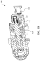
- FIG. 1B is a cross-sectional view of a screw compressor 100 shown in FIG. 1A along a length direction of the screw compressor and from rear to front;
- FIG. 1C is a cross-sectional view of a screw compressor 100 shown in FIG. 1A along a width direction of the screw compressor and section-cut to a discharge cavity 113 of the screw compressor 100.
- the screw compressor 100 includes a screw compressor housing 101.
- the screw compressor housing 101 defines a rotor cavity 111 and a discharge cavity 113.
- the rotor cavity 111 and the discharge cavity 113 communicate with each other via a communication port 112.
- a pair of rotors are disposed in the rotor cavity 111.
- the pair of rotors include a male rotor 121 and a female rotor (not shown).
- a compression cavity (not shown) is formed between the male rotor 121 and the female rotor, the compression cavity being enclosed by tooth surfaces of the male rotor 121 and the female rotor.
- the compression cavity can be in fluid communication with the discharge cavity 113 via the communication port 112.
- a gas enters a compression cavity between the male rotor 121 and the female rotor from an inlet of the screw compressor 100 (see FIG. 3 , i.e., a screw compressor inlet 302).
- the compression cavity will gradually become smaller and moves towards the communication port 112.
- the compressed gas in the compression cavity flows into the discharge cavity 113 via the communication port 112.
- Intermittently formed compressed fluid temporarily stays in the discharge cavity 113 to form a buffer, thereby forming relatively smooth airflow, flowing out of the screw compressor 100 through an outlet 188 (see FIG. 3 , i.e., a screw compressor outlet 306) of the screw compressor 100 disposed on the discharge cavity 113.
- Eight holes 122 are provided in a wall of the discharge cavity 113, the eight holes 122 are arranged in two rows, and each row includes four holes 122. The eight holes 122 all extend through the wall of the discharge cavity 113.
- the screw compressor 100 further includes an adjustment box 132.
- the adjustment box 132 is disposed on the screw compressor housing 101 and covers the eight holes 122. Components provided in the adjustment box 132 can fit with the eight holes 122, thereby reducing noise produced by the gas discharged from the screw compressor 100.
- the adjustment box 132 is provided with a communication port 134 connected with a lubricant system through a connecting pipe 150.
- the adjustment box 132, the components provided in the adjustment box 132 and the holes provided in the wall of the discharge cavity 113 form a silencing structure, and a specific fitting relationship of them will be described in conjunction with FIG. 2 .
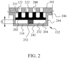
- FIG. 2 is a cross-sectional view of a first embodiment of a silencing structure shown in FIG. 1A , so as to show the fitting relationship between the adjustment box 132, the components in the adjustment box 132 and the screw compressor housing 101.
- the eight holes 122 are provided in the wall of the discharge cavity 113. Each of the eight holes 122 extends through the wall of the discharge cavity 113.
- the adjustment box 132 includes a substantially rectangular bottom wall 242, side walls 244 and connecting walls 246.
- the side walls 244 surround the bottom wall 242 and extend upwards from a circumferential edge of the bottom wall 242, and the connecting wall 246 extends outwards from an upper edge of the side wall 244.
- the adjustment box 132 is disposed on an outer side of the screw compressor housing 101 and covers the eight holes 122.
- the connecting wall 246 abuts against the screw compressor housing 101 and is connected with the outer side of the screw compressor housing 101 by means of connecting components (not shown) or welding or the like.
- the bottom wall and the side walls 244 of the adjustment box 132 enclose an adjustment cavity 204 together with the screw compressor housing 101.
- the adjustment cavity 204 is in fluid communication with the eight holes 122.
- the screw compressor 100 further includes an adjustment slider 202 and eight adjustment pistons 222.
- Each of the eight adjustment pistons 222 is a cylindrical body connected with an upper surface of the adjustment slider 202, so that the adjustment slider 202 and the eight adjustment pistons 222 can move together.
- a shape of each of the eight adjustment pistons 222 matches a corresponding one of the eight holes 122, so that each of the eight adjustment pistons 222 can be inserted into the corresponding one of the eight holes 122.
- the eight adjustment pistons 222 and the eight holes 122 are further configured such that the gas in the discharge cavity 113 does not flow into the adjustment cavity 204 when the eight adjustment pistons 222 move vertically in the eight holes 122.
- the eight holes 122 are each provided with an inlet end and a distal end opposite to the inlet end.
- the inlet end is formed by walls of the eight holes 122, and is in fluid communication with the discharge cavity 113.
- the eight adjustment pistons 222 are inserted into the corresponding holes 122 from the distal end.
- the eight adjustment pistons 222 and the eight holes 122 form eight silencing channels 288, respectively.
- one end of the silencing channel 288 is defined by the inlet end, and the other end thereof is defined by top portions of the eight adjustment pistons 222.
- a circumferential size of the adjustment slider 202 is configured to match the side walls 244 of the adjustment box 132, so that the adjustment cavity 204 is divided by the adjustment slider 202 into a first accommodation portion 231 and a second accommodation portion 232 separated from each other.
- the first accommodation portion 231 is formed on one side (i.e., an upper side of the adjustment slider 202) of the adjustment slider 202 close to the screw compressor housing 101, and the second accommodation portion 232 is formed between (i.e., a lower side of the adjustment slider 202) the adjustment slider 202 and the bottom wall 242 of the adjustment box 132.
- the bottom wall 242 of the adjustment box 132 is provided with a communication port 134 for being connected with a pressure source.
- the communication port 134 is connected with a lubricant circuit through the connecting pipe 150 (see FIG. 1A ), so that a lubricant can flow into the second accommodation portion 232 through the communication port 134.
- Pressure in the first accommodation portion 231 is substantially ambient pressure (i.e., one atmospheric pressure).
- the screw compressor 100 further includes a spring 252 for providing an auxiliary force for upward (i.e., towards the screw compressor housing 101) movement of the adjustment slider 202 in the adjustment box 132, and for limiting the range of downward movement of the adjustment slider 202.
- a spring 252 for providing an auxiliary force for upward (i.e., towards the screw compressor housing 101) movement of the adjustment slider 202 in the adjustment box 132, and for limiting the range of downward movement of the adjustment slider 202.
- one end of the spring 252 is connected with a lower surface of the adjustment slider 202, and the other end of the spring 252 is connected with the bottom wall 242 of the adjustment box 132.
- the spring 252 When the distance between a bottom portion of the adjustment slider 202 and a top portion of the bottom wall 242 is a predetermined distance H, the spring 252 is in a free state, that is, the spring 252 is not compressed or stretched, without exerting a force on the adjustment slider 202.
- the spring 252 When the distance between the bottom portion of the adjustment slider 202 and the top portion of the bottom wall 242 is greater than the predetermined distance H, the spring 252 is stretched, exerting a downward (i.e., away from the screw compressor housing 101) pulling force on the adjustment slider 202. When the distance between the bottom portion of the adjustment slider 202 and the top portion of the bottom wall 242 is less than the predetermined distance H, the spring 252 is compressed, exerting an upward (i.e., towards the screw compressor housing 101) thrust to the adjustment slider 202.
- a refrigerant is compressed in the screw compressor 100 into a high-temperature and high-pressure gas.
- the compressed gas enters the discharge cavity 113, producing an exhaust pulsation with relatively high acoustic energy.
- the exhaust pulsation not only causes vibration and noise, but also causes a device downstream of the screw compressor 100 in a refrigeration system to form a secondary sound source.
- the wall of the discharge cavity 113 of the screw compressor 100 of this application is provided with the silencing channels 288, capable of controlling propagation of the noise at a position closest to a noise-causing position.
- a frequency corresponding to peak energy of the exhaust pulsation of the screw compressor 100 is different, and a wavelength corresponding to its peak energy is also different.
- the length of the silencing channel 288 in the silencing structure of this application can be adjusted, thereby adapting to the peak wavelength under different working conditions, so as to reduce the peak energy of the exhaust pulsation and effectively perform silencing.
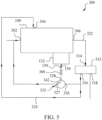
- FIG. 3 shows a partial system diagram of a refrigeration system 300 using a screw compressor 100 of this application.
- the lubricant is used as a power source for driving the adjustment slider 202 and the eight adjustment pistons 222 to move.
- the refrigeration system 300 includes the screw compressor 100.
- the screw compressor 100 includes a screw compressor inlet 302, a lubricant inlet 304 and a screw compressor outlet 306.
- the screw compressor inlet 302 is in fluid communication with the rotor cavity 111 for receiving a refrigerant from an evaporator (not shown) of the refrigeration system 300.
- the lubricant inlet 304 is in fluid communication with the rotor cavity 111 for receiving a lubricant from a lubricant separating apparatus 312.
- the screw compressor outlet 306 is in fluid communication with the discharge cavity 113 for discharging the compressed refrigerant and lubricant out of the screw compressor 100.
- the refrigeration system 300 further includes the lubricant separating apparatus 312.
- the lubricant separating apparatus 312 is configured to separate the refrigerant and the lubricant.
- the lubricant separating apparatus 312 includes a lubricant separating apparatus inlet 314, a lubricant outlet 316 and a refrigerant outlet 318.
- the lubricant separating apparatus inlet 314 is connected with the screw compressor outlet 306 through a first channel 322 for receiving compressed refrigerant and lubricant. After the refrigerant and the lubricant pass through the lubricant separating apparatus 312, the lubricant flows out of the lubricant outlet 316 and the refrigerant flows out of the refrigerant outlet 318.
- the lubricant outlet 316 is in fluid communication with the lubricant inlet 304 of the screw compressor through a second channel 324 for introducing the lubricant into the rotor cavity 111 of the screw compressor 100, thereby lubricating the male rotor 121 and the female rotor.
- the refrigerant flows from the refrigerant outlet 318 to a condenser (not shown) of the refrigeration system 300.
- the screw compressor 100, the first channel 322, the lubricant separating apparatus 312 and the second channel 324 form the lubricant circuit.
- the refrigeration system 300 further includes a switching apparatus 332.
- the switching apparatus 332 includes a first port 326, a second port 327, a third port 328, a switching apparatus first channel 341 and a switching apparatus second channel 342.
- the switching apparatus first channel 341 is configured to connect the first port 326 with the third port 328
- the switching apparatus second channel 342 is configured to connect the second port 327 with the third port 328.
- the first port 326 of the switching apparatus 332 is in fluid communication with the lubricant outlet 316 for introducing a high-pressure lubricant.
- the second port 327 of the switching apparatus 332 is in fluid communication with the screw compressor inlet 302 for making the high-pressure lubricant flow into the screw compressor 100.
- the third port 328 of the switching apparatus 332 is connected with the communication port 134 of the adjustment box 132 through the connecting pipe 150.
- the connecting pipe 150 is provided with a solenoid valve 360. Opening and closing of the solenoid valve 360 can be controlled, thereby controlling connection and disconnection of the connecting pipe 150.
- the screw compressor 100 further includes two acoustic sensors 351 and 352.
- the acoustic sensors 351 and 352 are arranged in the first channel 322. Detection ends (not shown) of the acoustic sensors 351 and 352 are in fluid communication with the first channel 322 so as to detect an exhaust pulsation energy value of the gas discharged from the screw compressor 100.
- the two acoustic sensors 351 and 352 are configured to detect the exhaust pulsation energy value of the gas discharged from the screw compressor 100, and therefore, the detection ends of the two acoustic sensors 351 and 352 can also be disposed in the discharge cavity 113.
- the screw compressor 100 further includes a position sensor 355 for detecting the distance between the adjustment slider 202 and the bottom wall 242 of the adjustment box 132. Since a wall thickness of the screw compressor housing 101, the distance from the bottom wall 242 of the adjustment box 132 to the screw compressor housing 101 and lengths of the eight adjustment pistons 222 are all fixed and known, the real-time silencing length can be obtained according to the distance between the adjustment slider 202 and the bottom wall 242 of the adjustment box 132 detected by the position sensor 355.
- the refrigeration system 300 further includes a controlling apparatus 301.
- the controlling apparatus 301 is connected with the acoustic sensors 351 and 352, the position sensor 355, the solenoid valve 360 and the switching apparatus 332 in a communicating manner.
- the controlling apparatus 301 can obtain the exhaust pulsation energy value of the gas discharged from the screw compressor 100 from the acoustic sensors 351 and 352, thereby working out a target silencing length.
- the controlling apparatus 301 can obtain the distance between the adjustment slider 202 and the bottom wall 242 of the adjustment box 132 from the position sensor 355, thereby working out a real-time silencing length.
- the controlling apparatus 301 can monitor the real-time silencing length, and adjust positions of the eight adjustment pistons 222 according to a relationship between the real-time silencing length and the target silencing length. For example, when the real-time silencing length is less than or greater than the target silencing length, the eight adjustment pistons 222 are moved downwards or upwards. When the real-time silencing length is equal to the target silencing length, the eight adjustment pistons 222 are made to stop moving and kept at current positions.
- the controlling apparatus 301 can also control opening or closing of the solenoid valve 360 and control the switching apparatus 332 to be in the first position or the second position.
- FIG. 4 shows a flow path diagram of a lubricant in a refrigeration system 300 when an adjustment slider 202 is moved upwards. Arrows indicate a flow path of the lubricant.
- the controlling apparatus 301 switches the switching apparatus 332 to the first position, so that the first channel 341 is connected while the second channel 342 is disconnected.
- the controlling apparatus 301 also opens the solenoid valve 360, so that the connecting pipe 150 is communicated. In this way, the lubricant is divided into two ways after flowing out from the lubricant outlet 316 of the lubricant separating apparatus 312.
- One way of lubricant enters the second accommodation portion 232 through the first port 326 and the third port 328 of the switching apparatus 332 and the communication port 134 of the adjustment box 132 in sequence, thereby controlling the movement of the adjustment slider 202 and the eight adjustment pistons 222.
- the other way of lubricant flows by following the lubricant circuit. Specifically, the lubricant enters the screw compressor 100 through the second channel 324 from the lubricant inlet 304 of the screw compressor.
- FIG. 5 shows a flow path diagram of a lubricant in a refrigeration system 300 when an adjustment slider 202 is moved downwards. Arrows indicate a flow path of the lubricant.
- the controlling apparatus 301 switches the switching apparatus 332 to the second position, so that the second channel 342 is connected while the first channel 341 is disconnected.
- the controlling apparatus 301 also opens the solenoid valve 360, so that the connecting pipe 150 is communicated.
- the lubricant flowing out from the second accommodation portion 232 enters the screw compressor inlet 302 via the communication port 134, the third port 328 and the second port 327 of the adjustment box 132 and flows into the screw compressor 100.
- FIG. 6 shows a schematic diagram of controlling movement of an adjustment slider 202 and an adjustment piston 222.
- the eight adjustment pistons 222 and the adjustment slider 202 are connected with each other, so that the eight adjustment pistons 222 and the adjustment slider 202 can move together. Movement directions of the eight adjustment pistons 222 and the adjustment slider 202 depend on a pressure difference between upper sides and lower sides of the eight adjustment pistons 222 and the adjustment slider 202.
- the second accommodation portion 232 is filled with the high-pressure lubricant, pressure on the lower sides of the eight adjustment pistons 222 and the adjustment slider 202 is greater than that on the upper sides of the eight adjustment pistons 222 and the adjustment slider 202, and the adjustment slider 202 and the adjustment pistons 222 move upwards, thereby reducing the length of the silencing channels 288.
- the second accommodation portion 232 communicates with a low pressure end (i.e., a suction end) of the screw compressor 100, the lubricant flows out of the second accommodation portion 232, and the adjustment slider 202 and the adjustment pistons 222 move downwards, thereby increasing the length of the silencing channels 288.
- the controlling apparatus 301 closes the solenoid valve 360, so that the adjustment slider 202 and the adjustment piston 222 are kept at current positions.
- the screw compressor 100 of this application can utilize the lubricant circuit in the refrigeration system 300, and thereby, the length of the silencing channel 288 is controlled by controlling the position of the adjustment piston 222 without requiring an additional drive source.
- the peak wavelength of the exhaust pulsation can be calculated by signals collected by the two acoustic sensors 351 and 352, thereby determining the length of the silencing channel 288, so as to achieve a silencing effect.
- the detection ends (not shown) of the two acoustic sensors 351 and 352 are disposed in the first channel 322 so as to obtain the exhaust pulsation energy value (for example, autopower spectra, cross-power spectra).
- S 11 and S 12 are the autopower spectra of signals picked up at the acoustic sensors 351 and 352
- C 12 and Q 12 are the cross-power spectra of the signals picked up at the acoustic sensors 351 and 352
- k is a wave number
- x 12 is a center distance between the acoustic sensor 351 and the acoustic sensor 352
- p i is the spectrum data of the exhaust pulsation energy.
- the frequency corresponding to the peak energy is extracted according to the worked out spectrum data p i of the exhaust pulsation energy, and sound velocity in an exhaust fluid is obtained from operating parameters of the screw compressor 100 (for example, the exhaust pressure, the exhaust temperature), and thereby, the wavelength corresponding to the peak energy can be worked out.
- the corresponding target silencing length is calculated from this wavelength.
- the controlling apparatus 301 controls the position of the adjustment piston 222 according to the worked out target silencing length, so that the actual length of the silencing channel 288 is consistent with the target silencing length.
- the silencing structure in the screw compressor 100 of this application can effectively reduce the exhaust pulsation in the discharge cavity 113, and can automatically adapt to different operating conditions to reduce a pulsation with prominent energy.
- the eight silencing channels 288 are formed in the silencing structure shown in FIG. 2 (only four silencing channels are shown in FIG. 2 , and the other four silencing channels are not shown), and each of the eight silencing channels 288 has a same length, and can be configured to perform silencing on a wavelength band corresponding to the peak energy. Specifically, when sound waves matching the silencing length are transmitted to the inlet end of the silencing channel, most of the sound waves are reflected due to a mismatch of acoustic impedance, and some sound waves are converted into heat energy due to a damping action and absorbed, so that only a small part of the sound waves can further propagate downstream to achieve silencing. As can be seen from FIG.
- the plurality of silencing channels are arranged in two rows, and are disposed along a travel route of the sound waves (for example, from the communication port 112 to the outlet of the screw compressor 100).
- the plurality of silencing channels disclosed along the travel route of the sound waves in the screw compressor 100 of this application can perform a plurality of silencing on the same wavelength band, thus greatly reducing the noise produced by the gas discharged from the screw compressor 100.
- FIG. 7 shows another embodiment of a drive mechanism of driving an adjustment slider 202 and eight adjustment pistons 222.
- the silencing structure shown in FIG. 7 is substantially the same as the silencing structure shown in FIG. 6 , and the description will not be repeated here.
- the difference from that shown in FIG. 6 is that the adjustment slider 202 and the eight adjustment pistons 222 shown in FIG. 6 take the lubricant as a drive source, while the adjustment slider 202 and the eight adjustment pistons 222 shown in FIG. 7 take a driving apparatus 701 as a drive source. More specifically, in an embodiment shown in FIG.
- the adjustment box 132 is provided with the communication port 134 for receiving the lubricant, and the movement of the adjustment slider 202 is controlled by controlling the lubricant accommodated in the second accommodation portion 232, thereby controlling the length of the silencing channel 288.
- This control method does not require an external power source, and the length of the silencing channel 288 can be controlled by using the lubricant in the refrigeration system 300, thereby reducing production cost and operation cost.
- the movement of the adjustment slider 202 is controlled by the driving apparatus 701, thereby controlling the length of the silencing channel 288. In this control method, there are fewer piping arrangements, and the length of the silencing channel 288 can be directly controlled by the driving apparatus 701.
- the driving apparatus 701 includes a body 703 and a rod 702.
- the rod 702 can extend and retract from the body 703 relative to the body 703.
- the adjustment box 132 is provided with a receiving port 710 for receiving the rod 702 of the driving apparatus 701.
- the rod 702 extends from the receiving port 710 into the adjustment cavity 204.
- a distal end of the rod 702 is connected with the adjustment slider 202, so that when the rod 702 extends, the eight adjustment pistons 222 move towards the screw compressor housing 101 together with the adjustment slider 202, so that the length of the silencing channel 288 is reduced.
- the eight adjustment pistons 222 move away from the screw compressor housing 101 together with the adjustment slider 202, so that the length of the silencing channel 288 is increased.
- the driving apparatus 701 is a motor.
- the controlling apparatus 301 is connected with the driving apparatus 701 in a communicating manner, thereby controlling start and stop of the driving apparatus 701.
- FIG. 8 shows a cross-sectional view of a second embodiment of a silencing structure.
- the similarities between the silencing structure shown in FIG. 8 and the silencing structure shown in FIG. 2 will not be repeated here.
- the difference from that shown in FIG. 2 is that each of the adjustment pistons 822 shown in FIG. 8 is provided with a blind hole 882.
- each of the adjustment pistons 822 is provided with a recess extending from one end surface to the other end. A diameter of the recess is slightly less than that of the adjustment piston 822.
- the silencing channel 888 is now formed jointly by parts of the eight holes 122 starting from the inlet end with the blind hole 882.
- the length of the silencing channel 288 is determined by the distance from the inlet end to the top portion of the adjustment piston 222.
- the silencing structure is suitable for application scenarios where the wall thickness of the screw compressor housing 101 is relatively large, or the target silencing length is relatively short. While in an embodiment of the silencing structure as shown in FIG. 8 , the silencing channel 888 is determined by the distance from the inlet end to a bottom of the recess of the adjustment piston.
- the silencing structure is suitable for application scenarios where the wall thickness of the screw compressor housing 101 is relatively small, or the target silencing length is relatively long, so as to reduce noise with a relatively long wavelength.
- the adjustment piston 822 when the length of the adjustment piston 822 is greater than that of the eight holes 122, the adjustment piston 822 can protrude inwards relative to an inner wall of the discharge cavity 113.
- the length of the silencing channel 888 is now determined by a depth of the blind hole 882 in the adjustment piston 822.
- FIG. 9 shows a cross-sectional view of a third embodiment of a silencing structure.
- the similarities between the silencing structure shown in FIG. 9 and the silencing structure shown in FIG. 2 will not be repeated here.
- the difference from that shown in FIG. 2 is that lengths of the eight adjustment pistons 922 shown in FIG. 9 are different. Therefore, lengths of the eight silencing channels 988 are also different.
- the eight silencing channels 988 with different lengths can perform silencing on sound waves of different wavelengths, respectively, thereby realizing that pulsations of a plurality of frequencies with more prominent energy are reduced simultaneously, so as to widen a silencing range.
- the lengths of some of the eight silencing channels 988 in the embodiment shown in FIG. 9 can be designed to match the wavelength corresponding to the peak energy, thereby reducing noise at the peak energy. While the length of the remaining silencing channels 988 can be designed to match a wavelength near the peak energy, thereby reducing other noise near the peak energy.
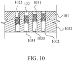
- FIG. 10 shows a cross-sectional view of a fourth embodiment of a silencing structure.
- the eight holes 122 are provided in the wall of the discharge cavity 113.
- Each of the eight holes 122 extends through the wall of the discharge cavity 113.
- the adjustment box 1032 is a cuboid, and eight adjustment cavities 1002 are disposed on the adjustment box.
- the eight adjustment cavities 1002 extend downwards from one side of the adjustment box 1032.
- the eight adjustment cavities 1002 are the same as the eight holes 122 in circumferential size, and are disposed in a one-to-one correspondence with the eight holes 122 so as to form a continuous channel.
- the eight adjustment pistons 1022 are each disposed in corresponding one of the eight channels, and divide each of the adjustment cavities 1002 into a first accommodation portion 1031 and a second accommodation portion 1033.
- the eight silencing channels are now formed by the eight holes 122 starting from the inlet end to the end surfaces of the adjustment pistons 1022.
- One side of the adjustment box 1032 opposite to the eight adjustment cavities 1002 is provided with eight communication ports 1034 corresponding to the second accommodation portion 1033 for being connected with the lubricant system so as to control the position of each adjustment piston 1022 in the channel.
- the eight communication ports 1034 are in fluid communication with the eight adjustment cavities 1002, respectively.
- each adjustment piston 1022 is provided with a protrusion portion, and the protrusion portion serves as a limit for downward movement of each adjustment piston 1022.
- the refrigeration system may include a plurality of third channels, a plurality of fourth channels and a plurality of switching apparatuses corresponding to the number of adjustment pistons 1022 so as to control the position of each adjustment piston 1022 in the channels by using the lubricant in the lubricant circuit. A specific control method thereof is similar to that described in FIG. 3 to FIG. 5 , and the description will not be repeated here.
- each adjustment piston 1022 in the channel can be independently controlled, thereby forming silencing channels with different silencing lengths.
- the silencing channels of different lengths can perform silencing on the noise of different wavelengths, and thereby, in addition to the wavelength corresponding to the peak energy, silencing can also be performed on wavelengths corresponding to other relatively high energy, broadening a silencing range.
- the silencing structures shown in FIG. 2 to FIG. 10 above are each provided with the silencing channels on the inner wall of the discharge cavity 113.
- the silencing channels When the sound waves matching the silencing length are transmitted to the inlet end of the silencing channel, most of the sound waves are reflected due to the fact that the presence of the silencing channels causes an acoustic impedance mismatch, and some sound waves are converted into heat energy due to a damping action and absorbed, so that only a small part of the sound waves can further propagate forwards to achieve silencing.
- the silencing length is different, sound waves at more frequency bands can be absorbed, thereby improving a silencing effect.
- FIG. 11 shows a cross-sectional view of a fifth embodiment of the silencing structure.
- a square hole 1122 is provided in the screw compressor housing 101.
- the width of the hole 1122 is approximately the sum of diameters of the eight holes 122 in the embodiment shown in FIG. 2 .
- the adjustment cavity 1104 of the adjustment box 132 communicates with the hole 1122 and forms a continuous channel.
- An adjustment piston 1142 is disposed in the continuous channel and can move in the continuous channel.
- the silencing channel 1188 is now formed by the hole 1122 starting from the inlet end to the end surface of the adjustment piston 1142. When the adjustment pistons 1142 move in the continuous channel, different silencing lengths can be formed.
- a plate 1144 is further disposed in the discharge cavity 113.
- the plate 1144 is provided with a several perforations 1110.
- the plate 1144 covers the hole 1122 and thereby covers the inlet end of the silencing channel 1188, so that the sound waves can pass through the several perforations 1110 and enter the channel formed by the adjustment cavity 1104 and the hole 1122.
- the perforations 1110 in the plate 1144 and the channels form a silencing structure.
- FIG. 12 shows a cross-sectional view of a sixth embodiment of a silencing structure.
- the embodiment shown in FIG. 12 is substantially the same as the embodiment shown in FIG. 11 , and the description will not be repeated here.
- the difference from the embodiment shown in FIG. 11 is that the discharge cavity 113 of the embodiment shown in FIG. 12 is provided with two plates 1242 and 1244.
- Several perforations are disposed in each of the two plates 1242 and 1244.
- the two plates 1242 and 1244 can move relative to each other, thereby changing alignment area of the several perforations. Aligned parts of the two plates 1242 and 1244 form an additional silencing channel, so that the discharge cavity 113 can communicate with the silencing channel 1188 through the several perforations.
- the pulsation wavelength mainly silenced by this silencing structure can be changed, thereby matching and reducing the peak energy under different operating conditions.
- this application provides a screw compressor, and the length of the silencing channel can be automatically adjusted according to the operating conditions (for example, the operating frequency, the exhaust temperature and the exhaust pressure) of the screw compressor, thereby effectively reducing the peak energy of exhaust pulsation under different operating conditions, reducing the noise.
- the operating conditions for example, the operating frequency, the exhaust temperature and the exhaust pressure
- the silencing structure of this application forms a portion of the silencing channel by providing holes in the inner wall, so that the silencing structure is small in size and compact in layout. This silencing structure does not increase flow resistance of the airflow and is easy to manufacture.
Landscapes
- Engineering & Computer Science (AREA)
- Mechanical Engineering (AREA)
- General Engineering & Computer Science (AREA)
- Physics & Mathematics (AREA)
- Thermal Sciences (AREA)
- Applications Or Details Of Rotary Compressors (AREA)
Applications Claiming Priority (2)
| Application Number | Priority Date | Filing Date | Title |
|---|---|---|---|
| CN202010273388.8A CN113513474B (zh) | 2020-04-09 | 2020-04-09 | 螺杆压缩机、制冷系统和制冷系统的控制方法 |
| PCT/CN2021/085653 WO2021204112A1 (zh) | 2020-04-09 | 2021-04-06 | 螺杆压缩机、制冷系统和制冷系统的控制方法 |
Publications (3)
| Publication Number | Publication Date |
|---|---|
| EP4134549A1 true EP4134549A1 (de) | 2023-02-15 |
| EP4134549A4 EP4134549A4 (de) | 2024-07-17 |
| EP4134549B1 EP4134549B1 (de) | 2026-01-21 |
Family
ID=78022572
Family Applications (1)
| Application Number | Title | Priority Date | Filing Date |
|---|---|---|---|
| EP21785574.1A Active EP4134549B1 (de) | 2020-04-09 | 2021-04-06 | Schraubenverdichter, kühlsystem und verfahren zur steuerung des kühlsystems |
Country Status (5)
| Country | Link |
|---|---|
| US (1) | US12297835B2 (de) |
| EP (1) | EP4134549B1 (de) |
| CN (1) | CN113513474B (de) |
| TW (1) | TW202140930A (de) |
| WO (1) | WO2021204112A1 (de) |
Families Citing this family (15)
| Publication number | Priority date | Publication date | Assignee | Title |
|---|---|---|---|---|
| CN114382696B (zh) * | 2022-01-18 | 2024-04-12 | 江苏新凯晟机械设备有限公司 | 一种具有过滤结构的空气压缩机 |
| CN115324892A (zh) * | 2022-08-16 | 2022-11-11 | 江森自控空调冷冻设备(无锡)有限公司 | 螺杆压缩机 |
| CN115492763B (zh) * | 2022-09-06 | 2025-02-14 | 江森自控空调冷冻设备(无锡)有限公司 | 螺杆压缩机 |
| CN116085255B (zh) * | 2023-02-16 | 2026-04-14 | 江森自控空调冷冻设备(无锡)有限公司 | 螺杆压缩机 |
| USD1117350S1 (en) * | 2023-06-06 | 2026-03-10 | Fujian Snowman Compressor Co., Ltd | Screw compressor |
| USD1093433S1 (en) * | 2023-06-06 | 2025-09-16 | Fujian Snowman Compressor Co., Ltd | Screw compressor |
| CN117028201A (zh) * | 2023-08-25 | 2023-11-10 | 珠海格力电器股份有限公司 | 消音器、压缩机及其控制方法和空调器 |
| USD1121687S1 (en) * | 2024-08-14 | 2026-04-07 | Fujian Snowman Compressor Co., Ltd | Screw compressor |
| USD1120027S1 (en) * | 2024-08-14 | 2026-03-24 | Fujian Snowman Compressor Co., Ltd | Screw compressor |
| USD1122302S1 (en) * | 2024-08-14 | 2026-04-14 | Fujian Snowman Compressor Co., Ltd | Screw compressor |
| USD1120029S1 (en) * | 2024-11-19 | 2026-03-24 | Fujian Snowman Compressor Co., Ltd | Screw compressor |
| USD1122987S1 (en) * | 2024-11-19 | 2026-04-21 | Fujian Snowman Compressor Co., Ltd | Screw compressor |
| USD1120028S1 (en) * | 2024-11-19 | 2026-03-24 | Fujian Snowman Compressor Co., Ltd | Screw compressor |
| USD1113998S1 (en) * | 2024-11-19 | 2026-02-17 | Fujian Snowman Compressor Co., Ltd | Screw compressor |
| CN120312595B (zh) * | 2025-06-04 | 2026-03-31 | 江苏五奥机泵制造有限公司 | 一种环保型真空节能泵 |
Family Cites Families (18)
| Publication number | Priority date | Publication date | Assignee | Title |
|---|---|---|---|---|
| JPH10318175A (ja) | 1997-05-21 | 1998-12-02 | Hitachi Ltd | スクリュー圧縮機 |
| DE10242139A1 (de) * | 2002-09-03 | 2004-03-18 | Bitzer Kühlmaschinenbau Gmbh | Schraubenverdichter |
| US20060165543A1 (en) * | 2005-01-24 | 2006-07-27 | York International Corporation | Screw compressor acoustic resonance reduction |
| WO2006096179A1 (en) | 2005-03-07 | 2006-09-14 | Carrier Corporation | Compressor sound suppression |
| US7568898B2 (en) | 2005-03-07 | 2009-08-04 | Carrier Corporation | Compressor sound suppression |
| WO2009045187A1 (en) * | 2007-10-01 | 2009-04-09 | Carrier Corporation | Screw compressor pulsation damper |
| CN101821479A (zh) | 2007-10-10 | 2010-09-01 | 开利公司 | 螺杆压缩机的滑阀系统 |
| US9140260B2 (en) | 2010-06-08 | 2015-09-22 | Hi-Bar Blowers, Inc. | Rotary lobe blower (pump) or vacuum pump with a shunt pulsation trap |
| US9243557B2 (en) | 2011-09-17 | 2016-01-26 | Paul Xiubao Huang | Shunt pulsation trap for positive displacement (PD) internal combustion engines (ICE) |
| CN102434337A (zh) * | 2011-09-28 | 2012-05-02 | 奇瑞汽车股份有限公司 | 一种消声频率可动态调节的共振消声器 |
| CN202326259U (zh) * | 2011-11-24 | 2012-07-11 | 江森自控空调冷冻设备(无锡)有限公司 | 带有消声结构的螺杆式压缩机及其转子座 |
| CN204402717U (zh) * | 2015-01-12 | 2015-06-17 | 曼胡默尔滤清器(上海)有限公司 | 模块式调音用可变体积谐振腔 |
| CN107654272A (zh) * | 2016-07-25 | 2018-02-02 | 上海汽车集团股份有限公司 | 用于汽车进气和排气调试的赫姆霍兹消声器 |
| JP2018031303A (ja) | 2016-08-25 | 2018-03-01 | 三菱重工サーマルシステムズ株式会社 | 圧縮機 |
| JP7065855B2 (ja) | 2016-12-20 | 2022-05-12 | キネティクス ドライヴ ソリューションズ インコーポレイテッド | 可変振動ダンパを有する流体静力学的駆動システム |
| CN107165825B (zh) | 2017-05-25 | 2020-02-07 | 珠海格力电器股份有限公司 | 泵体组件、压缩机和空调系统 |
| CN109210125B (zh) * | 2018-08-01 | 2020-10-23 | 西安交通大学苏州研究院 | 一种可调频自适应气流脉动衰减器 |
| CN109162920B (zh) * | 2018-08-30 | 2024-07-02 | 珠海格力电器股份有限公司 | 螺杆式压缩机 |
-
2020
- 2020-04-09 CN CN202010273388.8A patent/CN113513474B/zh active Active
-
2021
- 2021-04-06 US US17/917,535 patent/US12297835B2/en active Active
- 2021-04-06 WO PCT/CN2021/085653 patent/WO2021204112A1/zh not_active Ceased
- 2021-04-06 EP EP21785574.1A patent/EP4134549B1/de active Active
- 2021-04-08 TW TW110112800A patent/TW202140930A/zh unknown
Also Published As
| Publication number | Publication date |
|---|---|
| CN113513474A (zh) | 2021-10-19 |
| TW202140930A (zh) | 2021-11-01 |
| CN113513474B (zh) | 2023-02-21 |
| WO2021204112A1 (zh) | 2021-10-14 |
| US20230138965A1 (en) | 2023-05-04 |
| US12297835B2 (en) | 2025-05-13 |
| EP4134549B1 (de) | 2026-01-21 |
| EP4134549A4 (de) | 2024-07-17 |
Similar Documents
| Publication | Publication Date | Title |
|---|---|---|
| US12297835B2 (en) | Screw compressor, refrigeration system, and method for controlling refrigeration system | |
| US11732623B2 (en) | Muffler, compressor assembly, and refrigerator | |
| US8459963B2 (en) | Screw compressor pulsation damper | |
| US5584674A (en) | Noise attenuator of compressor | |
| JPH04292594A (ja) | 密閉型回転式圧縮機の騒音減少装置 | |
| US6149402A (en) | Suction muffler for hermetic reciprocating compressor | |
| CN108332406A (zh) | 消音装置及应用其的变频空调器 | |
| CN110067733A (zh) | 一种压缩机的消声结构及其消声方法 | |
| JP2003512568A (ja) | 側枝消音器を用いた往復圧縮機用の騒音低減装置 | |
| KR100538855B1 (ko) | 밀폐형 전동 압축기 | |
| CN211008996U (zh) | 消音器、压缩机和冰箱 | |
| JP2005083260A (ja) | スクリュー圧縮機および冷凍装置 | |
| EP4575231A1 (de) | Schraubenverdichter | |
| EP1450043A2 (de) | Kompressor | |
| US11920594B2 (en) | Screw compressor slide valve and screw compressor with gas pulsation attenuation function | |
| CN218325275U (zh) | 电动压缩机、空调系统及车辆 | |
| KR100448547B1 (ko) | 왕복동식 밀폐형 압축기 | |
| CN202056026U (zh) | 一种活塞式制冷压缩机的气缸座 | |
| KR101206811B1 (ko) | 밀폐형 압축기 | |
| US20030039559A1 (en) | Manifold assembly for a compressor | |
| CN218787184U (zh) | 降噪缓冲器、压缩机和电器 | |
| JP2013002289A (ja) | スクリュー圧縮機 | |
| CN222910269U (zh) | 一种旋转压缩机气缸和旋转压缩机 | |
| CN116988974B (zh) | 高压壳体组件、电动压缩机、空调系统和车辆 | |
| CN121025605A (zh) | 一种消声装置及空调机组 |
Legal Events
| Date | Code | Title | Description |
|---|---|---|---|
| STAA | Information on the status of an ep patent application or granted ep patent |
Free format text: STATUS: THE INTERNATIONAL PUBLICATION HAS BEEN MADE |
|
| PUAI | Public reference made under article 153(3) epc to a published international application that has entered the european phase |
Free format text: ORIGINAL CODE: 0009012 |
|
| STAA | Information on the status of an ep patent application or granted ep patent |
Free format text: STATUS: REQUEST FOR EXAMINATION WAS MADE |
|
| 17P | Request for examination filed |
Effective date: 20221021 |
|
| AK | Designated contracting states |
Kind code of ref document: A1 Designated state(s): AL AT BE BG CH CY CZ DE DK EE ES FI FR GB GR HR HU IE IS IT LI LT LU LV MC MK MT NL NO PL PT RO RS SE SI SK SM TR |
|
| DAV | Request for validation of the european patent (deleted) | ||
| DAX | Request for extension of the european patent (deleted) | ||
| A4 | Supplementary search report drawn up and despatched |
Effective date: 20240613 |
|
| RIC1 | Information provided on ipc code assigned before grant |
Ipc: F25B 49/02 20060101ALI20240607BHEP Ipc: F25B 31/00 20060101ALI20240607BHEP Ipc: F25B 1/047 20060101ALI20240607BHEP Ipc: F04C 28/28 20060101ALI20240607BHEP Ipc: F04C 23/02 20060101ALI20240607BHEP Ipc: F04C 29/12 20060101ALI20240607BHEP Ipc: F04C 29/00 20060101ALI20240607BHEP Ipc: F04C 29/06 20060101ALI20240607BHEP Ipc: F04C 29/02 20060101ALI20240607BHEP Ipc: F04C 18/16 20060101AFI20240607BHEP |
|
| GRAP | Despatch of communication of intention to grant a patent |
Free format text: ORIGINAL CODE: EPIDOSNIGR1 |
|
| STAA | Information on the status of an ep patent application or granted ep patent |
Free format text: STATUS: GRANT OF PATENT IS INTENDED |
|
| INTG | Intention to grant announced |
Effective date: 20250826 |
|
| GRAS | Grant fee paid |
Free format text: ORIGINAL CODE: EPIDOSNIGR3 |
|
| GRAA | (expected) grant |
Free format text: ORIGINAL CODE: 0009210 |
|
| STAA | Information on the status of an ep patent application or granted ep patent |
Free format text: STATUS: THE PATENT HAS BEEN GRANTED |
|
| AK | Designated contracting states |
Kind code of ref document: B1 Designated state(s): AL AT BE BG CH CY CZ DE DK EE ES FI FR GB GR HR HU IE IS IT LI LT LU LV MC MK MT NL NO PL PT RO RS SE SI SK SM TR |
|
| REG | Reference to a national code |
Ref country code: CH Ref legal event code: F10 Free format text: ST27 STATUS EVENT CODE: U-0-0-F10-F00 (AS PROVIDED BY THE NATIONAL OFFICE) Effective date: 20260121 |
|
| REG | Reference to a national code |
Ref country code: DE Ref legal event code: R096 Ref document number: 602021046417 Country of ref document: DE |
|
| REG | Reference to a national code |
Ref country code: IE Ref legal event code: FG4D |