EP4134509A1 - Installation of a window or door in an opening of a building - Google Patents
Installation of a window or door in an opening of a building Download PDFInfo
- Publication number
- EP4134509A1 EP4134509A1 EP22190040.0A EP22190040A EP4134509A1 EP 4134509 A1 EP4134509 A1 EP 4134509A1 EP 22190040 A EP22190040 A EP 22190040A EP 4134509 A1 EP4134509 A1 EP 4134509A1
- Authority
- EP
- European Patent Office
- Prior art keywords
- frame
- window
- opening
- door
- flange
- Prior art date
- Legal status (The legal status is an assumption and is not a legal conclusion. Google has not performed a legal analysis and makes no representation as to the accuracy of the status listed.)
- Pending
Links
Images


Classifications
-
- E—FIXED CONSTRUCTIONS
- E06—DOORS, WINDOWS, SHUTTERS, OR ROLLER BLINDS IN GENERAL; LADDERS
- E06B—FIXED OR MOVABLE CLOSURES FOR OPENINGS IN BUILDINGS, VEHICLES, FENCES OR LIKE ENCLOSURES IN GENERAL, e.g. DOORS, WINDOWS, BLINDS, GATES
- E06B1/00—Border constructions of openings in walls, floors, or ceilings; Frames to be rigidly mounted in such openings
- E06B1/02—Base frames, i.e. template frames for openings in walls or the like, provided with means for securing a further rigidly-mounted frame; Special adaptations of frames to be fixed therein
-
- E—FIXED CONSTRUCTIONS
- E06—DOORS, WINDOWS, SHUTTERS, OR ROLLER BLINDS IN GENERAL; LADDERS
- E06B—FIXED OR MOVABLE CLOSURES FOR OPENINGS IN BUILDINGS, VEHICLES, FENCES OR LIKE ENCLOSURES IN GENERAL, e.g. DOORS, WINDOWS, BLINDS, GATES
- E06B1/00—Border constructions of openings in walls, floors, or ceilings; Frames to be rigidly mounted in such openings
- E06B1/56—Fastening frames to the border of openings or to similar contiguous frames
- E06B1/60—Fastening frames to the border of openings or to similar contiguous frames by mechanical means, e.g. anchoring means
- E06B1/6046—Clamping means acting perpendicular to the wall opening; Fastening frames by tightening or drawing them against a surface parallel to the opening
- E06B1/6053—Clamping means acting perpendicular to the wall opening; Fastening frames by tightening or drawing them against a surface parallel to the opening the frame being moved perpendicularly towards the opening and held by means of snap action behind a protrusion on the border of the opening
-
- E—FIXED CONSTRUCTIONS
- E06—DOORS, WINDOWS, SHUTTERS, OR ROLLER BLINDS IN GENERAL; LADDERS
- E06B—FIXED OR MOVABLE CLOSURES FOR OPENINGS IN BUILDINGS, VEHICLES, FENCES OR LIKE ENCLOSURES IN GENERAL, e.g. DOORS, WINDOWS, BLINDS, GATES
- E06B1/00—Border constructions of openings in walls, floors, or ceilings; Frames to be rigidly mounted in such openings
- E06B1/56—Fastening frames to the border of openings or to similar contiguous frames
- E06B1/60—Fastening frames to the border of openings or to similar contiguous frames by mechanical means, e.g. anchoring means
- E06B1/6069—Separate spacer means acting exclusively in the plane of the opening; Shims; Wedges; Tightening of a complete frame inside a wall opening
- E06B1/6076—Separate spacer means acting exclusively in the plane of the opening; Shims; Wedges; Tightening of a complete frame inside a wall opening of screw-type
Definitions
- the invention relates to an assembly and a method for building a window or door into an opening of a building in order to create a high-quality construction node, with minimal so-called cold bridges.
- a window or door When a window or door is provided in a building, an opening is first provided in the building. The exact measurements of the opening must typically be known beforehand before manufacturing a window or door. This allows the window or door to fit correctly and to connect against edges of the opening in the building.
- a second aspect in providing a window or door in a building is related to insulation, watertightness, fire safety and airtightness of the building.
- a wall is typically constructed with an inner layer, also referred to as inner wall, an insulating layer and an outer layer, also referred to as outer wall.
- the window or the door is typically placed close to or against the outer wall in order to minimize undesired penetration of water.
- the inner wall is typically made first.
- the window or the door is then mounted before the insulation and outer wall are finished.
- the invention provides an assembly for building a window or door into an opening of a building, wherein the assembly comprises a self-supporting frame, which frame has a plurality of reveals, wherein at least two opposite reveals are provided with an inward directed flange so that the window or the door can be moved up against the flange between the opposite reveals, wherein the reveals comprise adjacently of the flange snap elements for snapping the window or door into place when it has been moved up against the flange.
- the combination of the opposite reveals, the flange and the snap elements is particularly advantageous for mounting a window or door in an opening. More specifically, this allows the self-supporting frame to already be mounted in the opening before the door or the window has been installed. Because the frame is self-supporting and comprises at least two reveals, the frame can be mounted such that it extends from the inner wall to a position beyond the outer wall to be built. Other mounting positions are also possible. More specifically, the flanges are then provided close to the outer wall. This makes it possible already to finish insulation and/or waterproofing and/or an airtight layer up to the self-supporting frame even before the window or door itself has been installed.
- the assembly is provided here with snap elements for holding the window in its final desired position. More specifically, the window or door snaps into place when it is pressed against the flange. Because the position of the frame has already been predetermined at that moment by fixing the frame onto the inner wall, the position of the window or the door is also predetermined. Because the window or door is pressed up against the flanges in its final position, the finish between the watertight finish between the flanges and the wall is indirectly also the watertight finish between the window or door and the wall.
- the assembly according to the invention thus provides a solution to a significant problem in installation of a window, i.e.
- the assembly provides many advantages for building a window or door into an opening of a building, particularly for windows and doors which are mounted against the outer wall. In this way a high-quality construction node is furthermore also created, with minimal so-called cold bridges, high insulation values, and optimal wind-, water- and airtightness, as well as better acoustics.
- Yet another advantage is based on the insight that the self-supporting frame is reusable after having been mounted. More specifically, an owner may decide to replace the windows after several years. New windows can be measured on the basis of the self-supporting frame. The old window can then be removed from the old self-supporting frame, which frame can then be reused for snapping a new window into.
- Reusing the self-supporting frame has the advantage that the optimal wind-, water- and airtightness is preserved since the self-supporting frame can be preserved in the wall and no alterations need be made thereto, this in contrast to known techniques. In known techniques breaking work is always needed, with this breaking work making the wind-, water- and airproofing of the new construction node extremely difficult. This often results in leaks, cold bridges and so on. By reusing the self-supporting frame the client will always have an optimal construction node, even in the event of a home renovation wherein new windows are provided.
- the inward directed flange is preferably provided with an elastic or compressible band for providing a watertight connection between the flange and the window or door after the snapping into place.
- the elastic band allows the window or door to be pressed up against the flange, wherein the elastic band is compressed and the snap elements snap the window or door into place.
- a snap element typically requires a certain clearance in order to hold the window or door against the flange. This clearance is accommodated by the elastic band. More specifically, the connection between the window or door and the flange remains watertight, even if the window of the door moves slightly away from the flange after the snapping. This simplifies the mounting and ensures proper functioning of the assembly for correctly mounting the window or door. In this way the insulation on the outer side can be connected much more accurately, and the brickwork can also already be finished relative to the opening.
- the frame is for this purpose preferably equipped with spacers which indicate the final position of the brickwork relative to the frame.
- the frame preferably comprises adjusting bolts for adjusting a position of the frame in the opening.
- the frame preferably comprises spacing screws for fixedly screwing the frame to the building with a determined distance between the frame and the building.
- the adjusting bolts and the spacing screws are preferably provided on the frame in pairs and in the vicinity of each other.
- the combination of adjusting bolts and spacing screws has great advantages in the mounting and correct positioning of the self-supporting frame of the assembly. In traditional construction, workers with the most experience typically also have back problems due to carrying out heavy work for many years. Workers who are strong and do not yet have any back problems are often young and inexperienced. This self-supporting frame must on the other hand be positioned in the opening of the building with great accuracy because the position of this frame will also determine the final position of the window or door.
- the mounting and positioning of the frame can be performed in two steps.
- a first step the frame is mounted in the opening without already mounting the frame in the final position here. This can be carried out by one or more strong and less experienced workers.
- a second step the position of the frame in the opening can be adjusted via the adjusting bolts. This then requires no hard labour, only experience. This second step can be performed by one experienced worker, even one with back problems.
- Providing the spacing screws and the adjusting bolts in pairs achieves the additional advantage that warping of the self-supporting frame during tightening of the spacing screws is minimized. This is because, when each spacing screw is provided in the vicinity of an adjusting bolt, the adjusting bolt provides counterforce when the spacing screw tightens.
- a spacing screw acts as a normal screw and has a tendency to pull the components that are being screwed toward each other.
- a spacing screw is preferably provided with screw thread over substantially its whole length so that two components can be held at a mutual distance. Adjusting bolts can preferably be reused for mounting a plurality of frames.
- the assembly preferably has at least two opposite hook elements which are connected to the self-supporting frame so as to act as stop when the self-supporting frame is placed into the opening of the building so that the hook elements hit an edge of the opening.
- the hook elements facilitate mounting of the frame in the opening. More specifically, the frame is prevented from being pushed through the opening.
- Adjusting bolts are preferably also provided on the hook elements so that the position of the frame can also be adjusted in a direction transversely of the opening. Hooks can preferably be reused for mounting a plurality of frames.
- the assembly preferably comprises a stop element which is arranged substantially parallel to and at a predetermined distance from the flange, wherein the flange and stop element are arranged on the same frame part of the frame.
- the stop element functions as stop surface for the window or door when the window or door are arranged in the frame before they are snapped against the flange. More specifically, the window or door will initially collide with the stop element while being arranged.
- the stop element functions as stop surface so that the window or door cannot continue to slide toward the flange and allows only a rotation of the window or door around the stop element. The window or door will therefore pivot around the stop element when it collides with the stop element.
- the invention further relates to a method for mounting a window or door in an opening of a building, wherein the method comprises of:
- Indirect measuring of an opening of the building can be done by determining the size of the opening, starting from the blueprint dimensions of the building.
- the mounting of the self-supporting frame preferably comprises the following sub-steps:
- Mounting of the windows and doors is further easier because the windows can be snapped into the self-supporting frame, whereby the windows and doors are automatically correctly positioned.
- the step of carrying the frame at least partially into the opening preferably further comprises of connecting at least two opposite hook elements to the frame and inserting the frame into the opening until the hook elements hit an edge of the opening.
- Advantages of the hook elements have been described above.
- the hooks are preferably reusable and do not form an integral part of the final frame.
- the step of positioning the frame preferably comprises of turning adjusting bolts which are positioned with a head against an edge of the opening and so adjusting a distance between the frame and the edge of the opening at the position of the adjusting bolts.
- By turning the adjusting bolt in a first direction the adjusting bolt moves outward out of the frame.
- the adjusting bolt hits an edge of the opening, the adjusting bolt pushes the frame away from the edge by the outward movement.
- By turning the adjusting bolt in the second direction the adjusting bolt moves inward and the adjusting bolt allows the frame to come closer to the edge of the opening. In this way an experienced worker can correctly position a frame in an opening using only a screwing machine and without exerting any considerable force. This can be done after the frame has been placed into the opening.
- the step of fixing the frame preferably comprises of screwing spacing screws into the edge of the opening and thereby fixedly screwing the frame to the building with a determined distance between the frame and the building. By screwing the frame in place the frame is fixed relative to the wall.
- the method preferably further comprises of removing the adjusting bolts after the frame has been fixed in the opening.
- the screws hold the frame relative to the wall so that the adjusting bolts can be removed and the inner side of the frame, the reveals, can thereby be free from protruding screws or bolts.
- the screw holes remaining behind can be used as additional fixing points for an optional additional spacing screw, or can be closed by matching plugs.
- the method preferably further comprises of connecting the edge of the opening of the building airtightly and/or watertightly to the self-supporting frame. This connecting can be done before the window or door is mounted in the frame, or thereafter.
- the method preferably further comprises of sliding the window or door against a stop element, which is arranged substantially parallel to and at a predetermined distance from the flange, and pivoting the door or window around the stop element.
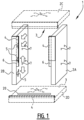
- Figure 1 shows an assembly 1 according to a first embodiment of the invention.
- a window or door can be mounted in an opening of a wall.
- the assembly has a frame with a plurality of frame parts 2A, 2B, 2C and 2D.
- the frame is self-supporting. This means that the frame is manufactured such that at least the length and width of the frame are fixed. Self-supporting preferably also means that when the frame is fixed to the wall, it forms a rigid structure which provides sufficient stability also to support the window or door, in addition to supporting itself.
- This aspect is further dependent on the materials from which the inner wall is constructed and the load-bearing capacity thereof, and in some situations additional corner anchors may therefore for instance be needed to obtain the necessary strength.
- the assembly 1 here bridges a distance between the window and the wall.
- the window can be mounted at any desired position via the frame. Both the window and the wall can be deemed a plane, and the window is typically positioned with its plane outside the plane of the wall. In other words, the window is typically connected to the inner wall and mounted at the position of the outer wall. Owing to the self-supporting frame, the assembly 1 forms a bridge between the inner wall and the window.
- the assembly 1 has a frame with two opposite frame parts 2A and 2B. These two opposite frame parts 2A and 2B are provided with an inward directed flange 4.
- the inward directed flange 4 is typically provided on a distal edge of the frame parts 2A and 2B. Alternatively, it can be provided at a different predetermined location on the frame.
- a reveal is defined as a straight, chamfered or profiled inner side of a window, gate, door or arch, oriented transversely or substantially transversely of the wall.
- the frame parts 2A and 2B are held at a distance from each other by further frame parts 2C and 2D.
- frame parts 2C and 2D are constructed similarly to frame parts 2A and 2B.
- the inner sides of frame parts 2C and 2D thereby also form reveals 3.
- Frame parts 2C and 2D can thus also be provided with a flange 4.
- the flanges 4 of the different frame parts 2A, 2B, 2C and 2D preferably connect substantially seamlessly to each other.
- Frame parts 2C and 2D can also be made in a different way.
- One or more of the frame parts 2C and 2D can for instance be provided only as connecting element, preferably rod-like or beam-like, between the frame parts 2A and 2B.
- Frame part 2C and/or 2D can also be formed as a profile connecting frame parts 2A and 2B. It is further also possible to dispense with one of the frame parts 2C and 2D.
- a frame with three parts can also fulfil the function of a self-supporting frame.
- the frame preferably has four parts.
- the upright frame part 2A and 2B are provided with snap elements 5.
- Snap elements are elements whereby a window or door can be snapped into place in the frame.
- Snap elements can take different forms.
- the snap elements are formed by a spring steel or plastic wedge-shaped element which can be compressed by the window or door when this is moved over the wedge shape, and such that the wedge-shaped element springs back to its original shape at least partially when the window or door reaches its final position.
- the wedge-shaped element thereby springs up behind an edge of the window or door so that the window or door is held in its desired position by the wedge-shaped element.
- Alternative fixing elements can thus for instance also be used, although these have the drawback that they take a more time-consuming form.
- the snap elements are placed on the opposite upward frame parts 2A and 2B such that a window or door which is slid between the upward frame parts 2A and 2B toward flange 4 snaps into place when the window or door comes to lie almost against flange 4.
- an elastic band 6 is provided against flange 4.
- flange 4 extends over substantially the whole length of each of the frame parts 2A and 2B and that band 6 extends over the whole flange.
- This construction allows a watertight and wind-tight connection to be realized between the flange and the window or door, via the elastic band, when the window or door has been snapped into the frame.
- the further advantage hereof is that a finish, i.e. a watertight finish or airtight finish or insulating finish or outer wall finish, can already be provided and finished against the flange even before the window or door has been mounted in the assembly. Because the window or the door can be connected watertightly and wind-tightly to the flange, the further finish is thereby also correct. This has been found to be a great advantage, particularly for efficiency on a work site.
- the above described advantages can also apply to this frame part.
- the lower frame part 2D is also provided with a flange 4 and elastic band 6.
- this frame part 2D can also take a different form, without flange and elastic band, so that a window sill can be placed under the window or door.
- the snap elements are in the shown embodiment of figure 1 provided on the upper frame parts 2A and 2B, it is possible to shift a window or door which has been snapped into the assembly in the height direction. Owing to the snap elements, the window or door will typically be centred between the upright frame parts 2A and 2B. The force of gravity will typically cause the window or door to position itself all the way at the bottom of the assembly. In the assembly according to the invention this can be corrected or adjusted in simple manner by exerting an upward force on the window or door, whereby the window or door is moved closer to the upper frame part 2C. This allows the window or door to be positioned at the most optimal functional and/or visual position in the frame.
- each frame part 2A, 2B, 2C and 2D has a plurality of screw holes 7. These screw holes are preferably provided in pairs, wherein each pair is provided with an adjusting bolt and with a spacing screw. Positioning screw holes can optionally also be provided, which is further elucidated with reference to figure 4 .
- Figure 2 shows a further embodiment.
- the lying frame parts 2C and 2D are provided with the snap elements 5.
- the upright frame parts 2A and 2B can be formed differently in order to connect the lying frame parts 2C and 2D.
- the explanation given above with reference to figure 1 similarly applies, as long as the lying frame parts 2C and 2D are deemed the most important frame parts in the embodiment of figure 2 .
- the embodiment of figure 2 is particularly applied in windows down to the floor, which typically comprise a plurality of parts such as sliding windows.
- window or door is slidable in horizontal direction after mounting. This allows the final position of the window or door to be adjusted in the horizontal direction.
- opposite reveals 3 are also formed by frame parts 2C and 2D. These frame parts 2C and 2D are further provided with flanges 4 and snap elements 5.
- Figure 3A shows that an upward frame part 2B is connected to a lying frame part 2C, and shows particularly that flange 4 of the upward frame part 2B is connected to the flange of the lying frame part 2C, thus forming an angle.
- the elastic band is here preferably also provided in order to form the corner, so that when the window is pressed against flanges 4, a watertight and airtight connection between the flanges is realized at the position of the corner.
- Figure 3B illustrates with arrows 8 how a window or door can be placed into the assembly.
- the window or door can be slid in the assembly, between the frame parts, until it is almost against flange 4, wherein the window or door is snapped into place in its final position via the snap elements 5.
- the window can still be moved upward and downward after being snapped into place in order to position the window fully in its optimal position.
- the optimal position can be related to a window sill and/or can be visual, wherein the distances between the window and the upright flanges are matched to the distance between the window and the upper flange.
- Figure 3C shows that an assembly can be built into a wall of a building.
- Figure 3C shows a wall with an inner wall 10, an insulating layer 11 and an outer wall 12. It will be apparent that each of these layers can be manufactured in different ways and from different materials.
- the assembly of the invention is aimed at facilitating installation of a window or door when the inner wall is constructed first on one side and wherein the window or door is mounted at the position of the outer wall. The skilled person will appreciate that this is a preferred application, but that the assembly can also be used in other situations and in other ways.
- Figure 3C shows that the screw holes 7 are provided at the position of the inner wall 10. This allows frame 2 to be connected to inner wall 10 even before insulation 11 and outer wall 12 have been formed. After frame 2 has been connected to inner wall 10, the insulation 11 around frame 2 can be finished.
- a watertight finishing layer can also be provided between the outer side of flange 4 and the outer side of inner wall 10 in order to prevent water from seeping in through the window or door.
- the frame is typically already provided with a watertight layer at the position of the flange over the whole width of the frame, so that only a connection between the frame and the inner wall need be made.
- An airtight layer can further be provided between inner wall 10 and frame 2.
- Outer wall 12 can also be manufactured taking into consideration the final position of flanges 4 against which the window or door is pressed. All this allows the wall and/or the finish to be completed with great accuracy even before the final window or door has been manufactured and before the window or door has been installed. For this purpose spacers are preferably provided to facilitate this.
- FIG 3C further shows that upright frame parts 2A and 2B can be provided with positioning holes 19. These positioning holes are formed at a predetermined distance 18 from flanges 4. These positioning holes make it possible in very simple manner to have the assembly protrude by a predetermined distance relative to inner wall 10. More specifically, the assembly will be provided with hooks, described below with reference to figure 4 . The hooks allow the assembly to be pushed into the opening of inner wall 10 without the assembly falling through the opening. The assembly can however easily be pushed 'too far' into the opening. By then turning positioning screws through the positioning openings a stop is created on the outer side of inner wall 10. When the assembly is then pulled back in, this can be done only until the positioning screws come up against the outer side of inner wall 10.
- flange 4 is guaranteed to be provided at a predetermined distance 18 from the outer side of inner wall 10. This distance 18 determines the thickness of the insulation and optionally also the thickness of the outer wall in order to predetermine the exact position of the window relative to the outer wall.
- Figure 4 illustrates that an assembly can be placed and correctly positioned in an opening of an inner wall in simple manner.
- Figure 4 shows an upper side and one upright side of the frame.
- the skilled person will appreciate that the described principles also apply to the underside and when the frame has two upright sides.
- the use of the adjusting bolts described below is further advantageous more specifically on the underside because the whole frame can thereby be lifted without a worker having to exert any considerable manual force for this purpose.
- Figure 4 shows a portion of the upright frame part 2A and a portion of the lying frame part 2C.
- Figures 1-3 show each of the frame parts with pairs of screw openings 7. The function of these pairs is illustrated in figure 4 . More specifically, an adjusting bolt 14 and a spacing screw 15 are preferably provided in each pair of screw holes.
- the adjusting bolt preferably has a flat tip so that the adjusting bolt does not have a tendency to fix itself in wall 10.
- the distance between the relevant frame part and the wall can hereby be set via the adjusting bolt. If the frame is too low, it is simple to turn an adjusting bolt in a lower frame part outward so that the frame thereby comes to lie higher as a whole. The distance can also be precisely controlled left-right. When a plurality of adjusting bolts are provided on one frame part, perpendicularity can also be controlled in simple manner. When there are more than two adjusting bolts, it is also possible to control warping of the relevant frame part.
- Figure 4 shows three adjusting bolts designated with numerals 14A, 14B and 14C.
- Each adjusting bolt acts in a different direction so that the adjusting bolts together allow for adjustment of the three-dimensional position of the assembly.
- the two opposite frame parts are typically provided with adjusting bolts so that the adjusting bolt on the one side can compensate for the adjusting bolt on the other side.
- Adjusting bolt 14C allows the frame to be pulled with the positioning screw against the outer side of the inner wall.
- the positioning screw is not shown, and can be screwed into the positioning holes 19 which are described above and shown in figure 3C .
- the depth of the assembly relative to the wall is thereby set correctly, as elucidated above.
- the hook 13 prevents the frame from accidentally falling through the opening when the frame is placed into the opening. This makes mounting of a frame in an opening very simple and possible in two steps.
- a first step the frame is physically placed into the opening. Because little knowledge and experience is needed for this, and because hooks 13 prevent the frame from being able to fall through the opening, this step can easily be performed by inexperienced workers. Once the frame has been placed in the opening, an experienced worker can use a screwing machine and typically also a spirit level to fine-tune the position of the frame in the opening via the adjusting bolts.
- a spacing screw is preferably provided close to each adjusting bolt situated in the frame, so not close to the adjusting bolt 14C situated in the hook.
- a spacing screw is a screw which can fix itself in the wall and in the frame and so hold the frame at a distance from the wall. Because each spacing screw is provided in the vicinity of an adjusting bolt, the correct positioning of the frame relative to the wall is maintained by the relevant adjusting bolt when the spacing screw is being screwed in. After the spacing screws have been screwed in, the adjusting bolts can be removed and hooks 13 can also be removed. All obstacles along the reveals are thereby removed so that the window or door can be mounted.
- Figure 5 shows a situation in which a window 16 is snapped into the assembly. More specifically, the window 16 is pressed with its window profiles up against the flange 4 with the elastic band 6. Window 16 thereby closes watertightly and airtightly against flange 4 via elastic band 6. As described above, this allows the wall to be finished and joined up to the flange 4 so that after mounting of the window the wall will be correctly finished and joined up to the window or door.
- the reveals can be finished in simple manner with premade finishing plates 17 in a range of shapes or materials. Because the exact depth of the assembly, the thickness of the window and the position of the assembly and the wall are known beforehand, the finishing plates can also already be premade and delivered.
- an inward directed flange 4 is in each case shown at an edge of the frame parts 2A, 2B, 2C and 2D.
- the flange can also be provided in a central zone of the frame parts so that a window can be mounted somewhere in the centre of the frame.
- the snap elements are in each case provided adjacently of and at a predetermined distance from the flange. In this way the window can be placed into and fixed in the frame from the inside.
- a stop element 20 can also be provided.
- the stop element 20 is arranged on frame part 2A, 2B, 2C and 2D, preferably a lower frame part 2D.
- the stop element 20 is arranged substantially parallel to and at a predetermined distance from the flange 4.
- Stop element 20 is arranged on an inner side of the frame. Stop element 20 functions as stop surface for the window or door when the window or door is arranged in the frame before being snapped against the flange 4. More specifically, the window or door will initially collide with stop element 20 while being arranged. Stop element 20 functions as stop surface so that the window or door cannot slide further toward flange 4 and allows only a rotation of the window or door around the stop element 20. When it collides with stop element 20, the window or door will therefore pivot around the stop element 20. This pivoting, also referred to as swinging movement, around stop element 20 will realize an acceleration on a side of the window or door lying opposite stop element 20, whereby the window or door will hit the flanges 4 with greater force and will thus snap into place more easily.
- the stop element is preferably arranged on a lower frame part 2D so that the window or door can be slid up to the stop element and the window or door can then swing around stop element 20 substantially free of friction. It is however also possible for the stop element to be provided with a similar effect on an upper frame part 2C or on one of the upright frame parts 2A, 2B, however in such a configuration the window or door will always experience frictional resistance, at least at the position of the lower frame part 2D. A further advantage of the swinging movement is that the window and the door are snapped against the flanges uniformly in the same primary direction.
Abstract
Description
- The invention relates to an assembly and a method for building a window or door into an opening of a building in order to create a high-quality construction node, with minimal so-called cold bridges.
- When a window or door is provided in a building, an opening is first provided in the building. The exact measurements of the opening must typically be known beforehand before manufacturing a window or door. This allows the window or door to fit correctly and to connect against edges of the opening in the building. A second aspect in providing a window or door in a building is related to insulation, watertightness, fire safety and airtightness of the building. A wall is typically constructed with an inner layer, also referred to as inner wall, an insulating layer and an outer layer, also referred to as outer wall. The window or the door is typically placed close to or against the outer wall in order to minimize undesired penetration of water. When a wall is built, the inner wall is typically made first. The window or the door is then mounted before the insulation and outer wall are finished. This allows the insulation and the outer wall to be finished neatly around the window. In a practical sense, mounting a window or door close to an outer wall when only the inner wall has been built causes problems. Support elements protruding beyond the outer wall are often connected to the inner wall so that the window or door can be mounted on these support elements. These support elements make it difficult for insulation and/or watertight film to connect properly, and form possible cold bridges. Mounting of the window or door on these supports is further a very delicate operation. When the window or door is large, and therefore heavy, it is difficult for workers to mount it correctly and accurately. Many workers develop back problems from lifting doors and windows and having to mount them accurately on support elements.
- It is an object of the invention to provide an assembly for building in a window or door whereby a window or door can be mounted accurately in simpler and less labour-intensive manner.
- For this purpose the invention provides an assembly for building a window or door into an opening of a building, wherein the assembly comprises a self-supporting frame, which frame has a plurality of reveals, wherein at least two opposite reveals are provided with an inward directed flange so that the window or the door can be moved up against the flange between the opposite reveals, wherein the reveals comprise adjacently of the flange snap elements for snapping the window or door into place when it has been moved up against the flange.
- The combination of the opposite reveals, the flange and the snap elements is particularly advantageous for mounting a window or door in an opening. More specifically, this allows the self-supporting frame to already be mounted in the opening before the door or the window has been installed. Because the frame is self-supporting and comprises at least two reveals, the frame can be mounted such that it extends from the inner wall to a position beyond the outer wall to be built. Other mounting positions are also possible. More specifically, the flanges are then provided close to the outer wall. This makes it possible already to finish insulation and/or waterproofing and/or an airtight layer up to the self-supporting frame even before the window or door itself has been installed. Once the window or the door has been manufactured, it can be slid between the reveals and up against the flanges from the inside. The assembly is provided here with snap elements for holding the window in its final desired position. More specifically, the window or door snaps into place when it is pressed against the flange. Because the position of the frame has already been predetermined at that moment by fixing the frame onto the inner wall, the position of the window or the door is also predetermined. Because the window or door is pressed up against the flanges in its final position, the finish between the watertight finish between the flanges and the wall is indirectly also the watertight finish between the window or door and the wall. The assembly according to the invention thus provides a solution to a significant problem in installation of a window, i.e. the accurate positioning of the often heavy window or the often heavy door, in that the self-supporting frame with the flanges already predetermines the final position of the window or the door. The window or door need thus merely be mounted in the frame, after which the positioning is automatically correct. An additional advantage is that the chance of damage to the window during mounting decreases significantly. On the basis of the above it will be apparent that the assembly provides many advantages for building a window or door into an opening of a building, particularly for windows and doors which are mounted against the outer wall. In this way a high-quality construction node is furthermore also created, with minimal so-called cold bridges, high insulation values, and optimal wind-, water- and airtightness, as well as better acoustics. Yet another advantage is based on the insight that the self-supporting frame is reusable after having been mounted. More specifically, an owner may decide to replace the windows after several years. New windows can be measured on the basis of the self-supporting frame. The old window can then be removed from the old self-supporting frame, which frame can then be reused for snapping a new window into. Reusing the self-supporting frame has the advantage that the optimal wind-, water- and airtightness is preserved since the self-supporting frame can be preserved in the wall and no alterations need be made thereto, this in contrast to known techniques. In known techniques breaking work is always needed, with this breaking work making the wind-, water- and airproofing of the new construction node extremely difficult. This often results in leaks, cold bridges and so on. By reusing the self-supporting frame the client will always have an optimal construction node, even in the event of a home renovation wherein new windows are provided.
- The inward directed flange is preferably provided with an elastic or compressible band for providing a watertight connection between the flange and the window or door after the snapping into place. The elastic band allows the window or door to be pressed up against the flange, wherein the elastic band is compressed and the snap elements snap the window or door into place. A snap element typically requires a certain clearance in order to hold the window or door against the flange. This clearance is accommodated by the elastic band. More specifically, the connection between the window or door and the flange remains watertight, even if the window of the door moves slightly away from the flange after the snapping. This simplifies the mounting and ensures proper functioning of the assembly for correctly mounting the window or door. In this way the insulation on the outer side can be connected much more accurately, and the brickwork can also already be finished relative to the opening. The frame is for this purpose preferably equipped with spacers which indicate the final position of the brickwork relative to the frame.
- The frame preferably comprises adjusting bolts for adjusting a position of the frame in the opening. The frame preferably comprises spacing screws for fixedly screwing the frame to the building with a determined distance between the frame and the building. The adjusting bolts and the spacing screws are preferably provided on the frame in pairs and in the vicinity of each other. The combination of adjusting bolts and spacing screws has great advantages in the mounting and correct positioning of the self-supporting frame of the assembly. In traditional construction, workers with the most experience typically also have back problems due to carrying out heavy work for many years. Workers who are strong and do not yet have any back problems are often young and inexperienced. This self-supporting frame must on the other hand be positioned in the opening of the building with great accuracy because the position of this frame will also determine the final position of the window or door. By providing adjusting bolts and spacing screws, the mounting and positioning of the frame can be performed in two steps. In a first step the frame is mounted in the opening without already mounting the frame in the final position here. This can be carried out by one or more strong and less experienced workers. In a second step the position of the frame in the opening can be adjusted via the adjusting bolts. This then requires no hard labour, only experience. This second step can be performed by one experienced worker, even one with back problems. Providing the spacing screws and the adjusting bolts in pairs achieves the additional advantage that warping of the self-supporting frame during tightening of the spacing screws is minimized. This is because, when each spacing screw is provided in the vicinity of an adjusting bolt, the adjusting bolt provides counterforce when the spacing screw tightens. A spacing screw acts as a normal screw and has a tendency to pull the components that are being screwed toward each other. On the other hand, a spacing screw is preferably provided with screw thread over substantially its whole length so that two components can be held at a mutual distance. Adjusting bolts can preferably be reused for mounting a plurality of frames.
- The assembly preferably has at least two opposite hook elements which are connected to the self-supporting frame so as to act as stop when the self-supporting frame is placed into the opening of the building so that the hook elements hit an edge of the opening. The hook elements facilitate mounting of the frame in the opening. More specifically, the frame is prevented from being pushed through the opening. Adjusting bolts are preferably also provided on the hook elements so that the position of the frame can also be adjusted in a direction transversely of the opening. Hooks can preferably be reused for mounting a plurality of frames.
- The assembly preferably comprises a stop element which is arranged substantially parallel to and at a predetermined distance from the flange, wherein the flange and stop element are arranged on the same frame part of the frame. The stop element functions as stop surface for the window or door when the window or door are arranged in the frame before they are snapped against the flange. More specifically, the window or door will initially collide with the stop element while being arranged. The stop element functions as stop surface so that the window or door cannot continue to slide toward the flange and allows only a rotation of the window or door around the stop element. The window or door will therefore pivot around the stop element when it collides with the stop element. This swinging movement around the stop element will realize an acceleration on a side of the window or door lying opposite the stop element, whereby the window or door will hit the flanges with greater force and will thus snap into place more easily. This simplifies and facilitates the work of the installer further.
- The invention further relates to a method for mounting a window or door in an opening of a building, wherein the method comprises of:
- directly or indirectly measuring the opening of the building;
- manufacturing a self-supporting frame which fits in the opening, which frame has a plurality of reveals with reveal dimensions, wherein at least two opposite reveals are provided with an inward directed flange, wherein the reveals adjacently of the flange comprise snap elements for snapping the window or door into place;
- manufacturing a window or door with outer dimensions which are related to the reveal dimensions;
- mounting the self-supporting frame in the opening of the building;
- snapping the window or door into the frame against the flange.
- Indirect measuring of an opening of the building can be done by determining the size of the opening, starting from the blueprint dimensions of the building.
- The mounting of the self-supporting frame preferably comprises the following sub-steps:
- carrying the frame at least partially into the opening;
- positioning the frame inside the opening;
- fixing the frame in the opening.
- In traditional construction windows and doors are ordered after the openings of the building, provided in the inner wall, have been measured. Certain work on site will then frequently come to a standstill until the windows have been manufactured and delivered. This is not efficient. By providing the self-supporting frame it is no longer necessary to measure and work can be continued, more specifically, a watertight layer and/or airtight layer and/or insulation can be finished against the self-supporting frame, which is described above.
- Mounting of the windows and doors is further easier because the windows can be snapped into the self-supporting frame, whereby the windows and doors are automatically correctly positioned.
- The step of carrying the frame at least partially into the opening preferably further comprises of connecting at least two opposite hook elements to the frame and inserting the frame into the opening until the hook elements hit an edge of the opening. Advantages of the hook elements have been described above. The hooks are preferably reusable and do not form an integral part of the final frame.
- The step of positioning the frame preferably comprises of turning adjusting bolts which are positioned with a head against an edge of the opening and so adjusting a distance between the frame and the edge of the opening at the position of the adjusting bolts. By turning the adjusting bolt in a first direction the adjusting bolt moves outward out of the frame. When the adjusting bolt hits an edge of the opening, the adjusting bolt pushes the frame away from the edge by the outward movement. By turning the adjusting bolt in the second direction the adjusting bolt moves inward and the adjusting bolt allows the frame to come closer to the edge of the opening. In this way an experienced worker can correctly position a frame in an opening using only a screwing machine and without exerting any considerable force. This can be done after the frame has been placed into the opening.
- The step of fixing the frame preferably comprises of screwing spacing screws into the edge of the opening and thereby fixedly screwing the frame to the building with a determined distance between the frame and the building. By screwing the frame in place the frame is fixed relative to the wall.
- The method preferably further comprises of removing the adjusting bolts after the frame has been fixed in the opening. The screws hold the frame relative to the wall so that the adjusting bolts can be removed and the inner side of the frame, the reveals, can thereby be free from protruding screws or bolts. The screw holes remaining behind can be used as additional fixing points for an optional additional spacing screw, or can be closed by matching plugs.
- The method preferably further comprises of connecting the edge of the opening of the building airtightly and/or watertightly to the self-supporting frame. This connecting can be done before the window or door is mounted in the frame, or thereafter.
- The method preferably further comprises of sliding the window or door against a stop element, which is arranged substantially parallel to and at a predetermined distance from the flange, and pivoting the door or window around the stop element.
- The invention will now be further described on the basis of exemplary embodiments shown in the drawings.
- In the drawing:
-
figure 1 shows an exploded view of an assembly according to a first embodiment of the invention; -
figure 2 shows an exploded view of an assembly according to a second embodiment of the invention; -
figures 3A, 3B and 3C show a segment of an assembly according to an embodiment in different states and with different designations; -
figure 4 shows an adjustment of an assembly according to an embodiment of the invention; and -
figure 5 shows a further state of a segment of an assembly according to an embodiment of the invention. - The same or similar elements are designated in the drawings with the same reference numerals.
-
Figure 1 shows anassembly 1 according to a first embodiment of the invention. With this assembly 1 a window or door can be mounted in an opening of a wall. For this purpose the assembly has a frame with a plurality offrame parts assembly 1 here bridges a distance between the window and the wall. In other words, the window can be mounted at any desired position via the frame. Both the window and the wall can be deemed a plane, and the window is typically positioned with its plane outside the plane of the wall. In other words, the window is typically connected to the inner wall and mounted at the position of the outer wall. Owing to the self-supporting frame, theassembly 1 forms a bridge between the inner wall and the window. - In the embodiment of
figure 1 theassembly 1 has a frame with twoopposite frame parts opposite frame parts flange 4. The inward directedflange 4 is typically provided on a distal edge of theframe parts opposite frame parts - The
frame parts further frame parts embodiment frame parts parts frame parts Frame parts flange 4. Theflanges 4 of thedifferent frame parts Frame parts frame parts frame parts Frame part 2C and/or 2D can also be formed as a profile connectingframe parts frame parts - In the embodiment of
figure 1 theupright frame part snap elements 5. Snap elements are elements whereby a window or door can be snapped into place in the frame. Snap elements can take different forms. In one form, the snap elements are formed by a spring steel or plastic wedge-shaped element which can be compressed by the window or door when this is moved over the wedge shape, and such that the wedge-shaped element springs back to its original shape at least partially when the window or door reaches its final position. The wedge-shaped element thereby springs up behind an edge of the window or door so that the window or door is held in its desired position by the wedge-shaped element. The skilled person will appreciate that this is just one embodiment and that different kinds and types of snap element can be provided for snapping the window or door into place in its final position. Alternative fixing elements can thus for instance also be used, although these have the drawback that they take a more time-consuming form. - The snap elements are placed on the opposite
upward frame parts upward frame parts flange 4 snaps into place when the window or door comes to lie almost againstflange 4. In order to realize a good seal betweenflange 4 and the window or door anelastic band 6 is provided againstflange 4. In the figures a part of theflange 4 has been omitted from the drawing in order to show where and how theband 6 is placed. It will be apparent thatflange 4 extends over substantially the whole length of each of theframe parts band 6 extends over the whole flange. This construction allows a watertight and wind-tight connection to be realized between the flange and the window or door, via the elastic band, when the window or door has been snapped into the frame. The further advantage hereof is that a finish, i.e. a watertight finish or airtight finish or insulating finish or outer wall finish, can already be provided and finished against the flange even before the window or door has been mounted in the assembly. Because the window or the door can be connected watertightly and wind-tightly to the flange, the further finish is thereby also correct. This has been found to be a great advantage, particularly for efficiency on a work site. - By also providing the
upper frame part 2C with aflange 4 andelastic band 6 the above described advantages can also apply to this frame part. In the shown embodiment thelower frame part 2D is also provided with aflange 4 andelastic band 6. Alternatively, thisframe part 2D can also take a different form, without flange and elastic band, so that a window sill can be placed under the window or door. - Because the snap elements are in the shown embodiment of
figure 1 provided on theupper frame parts upright frame parts upper frame part 2C. This allows the window or door to be positioned at the most optimal functional and/or visual position in the frame. -
Figure 1 further shows that eachframe part figure 4 . -
Figure 2 shows a further embodiment. Infigure 2 the lyingframe parts snap elements 5. Theupright frame parts frame parts figure 1 similarly applies, as long as the lyingframe parts figure 2 . - The embodiment of
figure 2 is particularly applied in windows down to the floor, which typically comprise a plurality of parts such as sliding windows. In the embodiment offigure 2 window or door is slidable in horizontal direction after mounting. This allows the final position of the window or door to be adjusted in the horizontal direction. In the embodiment offigure 2 opposite reveals 3 are also formed byframe parts frame parts flanges 4 and snapelements 5. -
Figure 3A shows that anupward frame part 2B is connected to a lyingframe part 2C, and shows particularly thatflange 4 of theupward frame part 2B is connected to the flange of the lyingframe part 2C, thus forming an angle. The elastic band is here preferably also provided in order to form the corner, so that when the window is pressed againstflanges 4, a watertight and airtight connection between the flanges is realized at the position of the corner. -
Figure 3B illustrates witharrows 8 how a window or door can be placed into the assembly. On the basis of the above explanation it will be apparent that the window or door can be slid in the assembly, between the frame parts, until it is almost againstflange 4, wherein the window or door is snapped into place in its final position via thesnap elements 5. This allows extremely simple mounting of a window or door because the final position has already been largely determined. In the shown embodiment offigure 3B , which corresponds to the embodiment offigure 1 , the window can still be moved upward and downward after being snapped into place in order to position the window fully in its optimal position. This is designated witharrows 9. The optimal position can be related to a window sill and/or can be visual, wherein the distances between the window and the upright flanges are matched to the distance between the window and the upper flange. -
Figure 3C shows that an assembly can be built into a wall of a building.Figure 3C shows a wall with aninner wall 10, an insulatinglayer 11 and anouter wall 12. It will be apparent that each of these layers can be manufactured in different ways and from different materials. The assembly of the invention is aimed at facilitating installation of a window or door when the inner wall is constructed first on one side and wherein the window or door is mounted at the position of the outer wall. The skilled person will appreciate that this is a preferred application, but that the assembly can also be used in other situations and in other ways. -
Figure 3C shows that the screw holes 7 are provided at the position of theinner wall 10. This allows frame 2 to be connected toinner wall 10 even beforeinsulation 11 andouter wall 12 have been formed. After frame 2 has been connected toinner wall 10, theinsulation 11 around frame 2 can be finished. A watertight finishing layer can also be provided between the outer side offlange 4 and the outer side ofinner wall 10 in order to prevent water from seeping in through the window or door. The frame is typically already provided with a watertight layer at the position of the flange over the whole width of the frame, so that only a connection between the frame and the inner wall need be made. An airtight layer can further be provided betweeninner wall 10 and frame 2.Outer wall 12 can also be manufactured taking into consideration the final position offlanges 4 against which the window or door is pressed. All this allows the wall and/or the finish to be completed with great accuracy even before the final window or door has been manufactured and before the window or door has been installed. For this purpose spacers are preferably provided to facilitate this. -
Figure 3C further shows thatupright frame parts predetermined distance 18 fromflanges 4. These positioning holes make it possible in very simple manner to have the assembly protrude by a predetermined distance relative toinner wall 10. More specifically, the assembly will be provided with hooks, described below with reference tofigure 4 . The hooks allow the assembly to be pushed into the opening ofinner wall 10 without the assembly falling through the opening. The assembly can however easily be pushed 'too far' into the opening. By then turning positioning screws through the positioning openings a stop is created on the outer side ofinner wall 10. When the assembly is then pulled back in, this can be done only until the positioning screws come up against the outer side ofinner wall 10. In thisstate flange 4 is guaranteed to be provided at apredetermined distance 18 from the outer side ofinner wall 10. Thisdistance 18 determines the thickness of the insulation and optionally also the thickness of the outer wall in order to predetermine the exact position of the window relative to the outer wall. -
Figure 4 illustrates that an assembly can be placed and correctly positioned in an opening of an inner wall in simple manner.Figure 4 shows an upper side and one upright side of the frame. The skilled person will appreciate that the described principles also apply to the underside and when the frame has two upright sides. The use of the adjusting bolts described below is further advantageous more specifically on the underside because the whole frame can thereby be lifted without a worker having to exert any considerable manual force for this purpose.Figure 4 shows a portion of theupright frame part 2A and a portion of the lyingframe part 2C.Figures 1-3 show each of the frame parts with pairs ofscrew openings 7. The function of these pairs is illustrated infigure 4 . More specifically, an adjusting bolt 14 and a spacing screw 15 are preferably provided in each pair of screw holes. The adjusting bolt preferably has a flat tip so that the adjusting bolt does not have a tendency to fix itself inwall 10. The distance between the relevant frame part and the wall can hereby be set via the adjusting bolt. If the frame is too low, it is simple to turn an adjusting bolt in a lower frame part outward so that the frame thereby comes to lie higher as a whole. The distance can also be precisely controlled left-right. When a plurality of adjusting bolts are provided on one frame part, perpendicularity can also be controlled in simple manner. When there are more than two adjusting bolts, it is also possible to control warping of the relevant frame part.Figure 4 shows three adjusting bolts designated withnumerals bolt 14C allows the frame to be pulled with the positioning screw against the outer side of the inner wall. The positioning screw is not shown, and can be screwed into the positioning holes 19 which are described above and shown infigure 3C . The depth of the assembly relative to the wall is thereby set correctly, as elucidated above. Thehook 13 prevents the frame from accidentally falling through the opening when the frame is placed into the opening. This makes mounting of a frame in an opening very simple and possible in two steps. In a first step the frame is physically placed into the opening. Because little knowledge and experience is needed for this, and becausehooks 13 prevent the frame from being able to fall through the opening, this step can easily be performed by inexperienced workers. Once the frame has been placed in the opening, an experienced worker can use a screwing machine and typically also a spirit level to fine-tune the position of the frame in the opening via the adjusting bolts. - A spacing screw is preferably provided close to each adjusting bolt situated in the frame, so not close to the adjusting
bolt 14C situated in the hook. A spacing screw is a screw which can fix itself in the wall and in the frame and so hold the frame at a distance from the wall. Because each spacing screw is provided in the vicinity of an adjusting bolt, the correct positioning of the frame relative to the wall is maintained by the relevant adjusting bolt when the spacing screw is being screwed in. After the spacing screws have been screwed in, the adjusting bolts can be removed and hooks 13 can also be removed. All obstacles along the reveals are thereby removed so that the window or door can be mounted. -
Figure 5 shows a situation in which awindow 16 is snapped into the assembly. More specifically, thewindow 16 is pressed with its window profiles up against theflange 4 with theelastic band 6.Window 16 thereby closes watertightly and airtightly againstflange 4 viaelastic band 6. As described above, this allows the wall to be finished and joined up to theflange 4 so that after mounting of the window the wall will be correctly finished and joined up to the window or door. On the inner side the reveals can be finished in simple manner with premade finishingplates 17 in a range of shapes or materials. Because the exact depth of the assembly, the thickness of the window and the position of the assembly and the wall are known beforehand, the finishing plates can also already be premade and delivered. This allows for very rapid finishing of the reveals after the window or door has been mounted. This saves a lot of difficult work for a plasterer, so that this aspect also saves considerable costs. What's more, they can form a guide for the plasterer for plastering a straight wall inside. - In the figures an inward directed
flange 4 is in each case shown at an edge of theframe parts stop element 20 can also be provided. Thestop element 20 is arranged onframe part lower frame part 2D. Thestop element 20 is arranged substantially parallel to and at a predetermined distance from theflange 4. Stopelement 20 is arranged on an inner side of the frame. Stopelement 20 functions as stop surface for the window or door when the window or door is arranged in the frame before being snapped against theflange 4. More specifically, the window or door will initially collide withstop element 20 while being arranged. Stopelement 20 functions as stop surface so that the window or door cannot slide further towardflange 4 and allows only a rotation of the window or door around thestop element 20. When it collides withstop element 20, the window or door will therefore pivot around thestop element 20. This pivoting, also referred to as swinging movement, aroundstop element 20 will realize an acceleration on a side of the window or door lyingopposite stop element 20, whereby the window or door will hit theflanges 4 with greater force and will thus snap into place more easily. The stop element is preferably arranged on alower frame part 2D so that the window or door can be slid up to the stop element and the window or door can then swing aroundstop element 20 substantially free of friction. It is however also possible for the stop element to be provided with a similar effect on anupper frame part 2C or on one of theupright frame parts lower frame part 2D. A further advantage of the swinging movement is that the window and the door are snapped against the flanges uniformly in the same primary direction. This is understood to mean that the window or door is snapped into place in one swinging movement, this in contrast to the situation where each side of the window is for instance snapped into place one at a time. Such a swinging movement is less susceptible to error because incorrect orientations of the window or door are avoided and a correct mounting of the window is substantially guaranteed. These options all form embodiments of the assembly for building a window or door into an opening of the building. This allows a window to be installed, depending on the visual and practical wishes of a designer, at the position of the inner wall, at the position of the outer wall, between outer wall and inner wall, protruding inward or outward from the wall. This also allows the mounting direction to be selected on the basis of the final position of the window and/or in combination with practical conditions of the project. - The skilled person will appreciate on the basis of the above description that the invention can be embodied in different ways and on the basis of different principles. The invention is not limited to the above described embodiments. The above described embodiments and the figures are purely illustrative and serve only to increase understanding of the invention. The invention will not therefore be limited to the embodiments described herein, but is defined in the claims.
Claims (15)
- Assembly for building a window or door into an opening of a building, wherein the assembly comprises a self-supporting frame, which frame has a plurality of reveals, wherein at least two opposite reveals are provided with an inward directed flange so that the window or the door can be moved up against the flange between the opposite reveals, wherein the reveals comprise adjacently of the flange snap elements for snapping the window or door into place when it has been moved up against the flange.
- Assembly according to claim 1, wherein the inward directed flange is provided with an elastic band for providing a watertight connection between the flange and the window or door after the snapping into place.
- Assembly according to claim 1 or 2, wherein the frame comprises adjusting bolts for adjusting a position of the frame in the opening.
- Assembly according to any one of the foregoing claims, wherein the frame comprises spacing screws for fixedly screwing the frame to the building with a determined distance between the frame and the building.
- Assembly according to claims 3 and 4, wherein the adjusting bolts and the spacing screws are provided on the frame in pairs and in the vicinity of each other.
- Assembly according to any one of the foregoing claims, wherein the assembly has at least two opposite hook elements which are connected to the self-supporting frame so as to act as stop when the self-supporting frame is placed into the opening of the building so that the hook elements hit an edge of the opening.
- Assembly according to any one of the foregoing claims, further comprising a stop element which is arranged substantially parallel to and at a predetermined distance from the flange, wherein the flange and stop element are arranged on the same frame part of the frame.
- Method for mounting a window or door in an opening of a building, wherein the method comprises of:- measuring the opening of the building;- manufacturing a self-supporting frame which fits in the opening, which frame has a plurality of reveals with reveal dimensions, wherein at least two opposite reveals are provided with an inward directed flange, wherein the reveals adjacently of the flange comprise snap elements for snapping the window or door into place;- manufacturing a window or door with outer dimensions which are related to the reveal dimensions;- mounting the self-supporting frame in the opening of the building;- snapping the window or door into the frame against the flange.
- Method according to the foregoing claim, wherein mounting of the self-supporting frame comprises the following sub-steps:- carrying the frame at least partially into the opening;- positioning the frame inside the opening;- fixing the frame in the opening.
- Method according to the foregoing claim, wherein the step of carrying the frame at least partially into the opening further comprises of connecting at least two opposite hook elements to the frame and inserting the frame into the opening until the hook elements hit an edge of the opening.
- Method according to any one of the claims 9-10, wherein the step of positioning the frame comprises of turning adjusting bolts which are positioned with a head against an edge of the opening and so adjusting a distance between the frame and the edge of the opening at the position of the adjusting bolts.
- Method according to any one of the claims 9-11, wherein the step of fixing the frame comprises of screwing spacing screws into the edge of the opening and thereby fixedly screwing the frame to the building with a determined distance between the frame and the building.
- Method according to any one of the foregoing claims 9-12 and claim 10, further comprising of removing the adjusting bolts after the frame has been fixed in the opening.
- Method according to any one of the foregoing claims 8-13, further comprising of connecting the edge of the opening of the building airtightly and/or watertightly to the self-supporting frame.
- Method according to any one of the foregoing claims 8-14, further comprising of sliding the window or door against a stop element, which is arranged substantially parallel to and at a predetermined distance from the flange, and pivoting the window or door around the stop element.
Applications Claiming Priority (1)
| Application Number | Priority Date | Filing Date | Title |
|---|---|---|---|
| BE20215645A BE1029672B1 (en) | 2021-08-13 | 2021-08-13 | Installation of a window or door in an opening of the building |
Publications (1)
| Publication Number | Publication Date |
|---|---|
| EP4134509A1 true EP4134509A1 (en) | 2023-02-15 |
Family
ID=77358034
Family Applications (1)
| Application Number | Title | Priority Date | Filing Date |
|---|---|---|---|
| EP22190040.0A Pending EP4134509A1 (en) | 2021-08-13 | 2022-08-11 | Installation of a window or door in an opening of a building |
Country Status (2)
| Country | Link |
|---|---|
| EP (1) | EP4134509A1 (en) |
| BE (1) | BE1029672B1 (en) |
Citations (6)
| Publication number | Priority date | Publication date | Assignee | Title |
|---|---|---|---|---|
| DE3420626A1 (en) * | 1984-06-02 | 1985-12-05 | Fa. Schüt-Duis, 2960 Aurich | Window frame with case inserted therein made of plastic profile |
| WO1998001647A1 (en) * | 1996-07-04 | 1998-01-15 | Soederstroem Kurt | Fastener for adjustable fastening of a frame in a wall-opening |
| GB2389383A (en) * | 2002-05-28 | 2003-12-10 | David Salisbury Joinery Ltd | A window assembly |
| WO2009069080A1 (en) * | 2007-11-26 | 2009-06-04 | Pierre Jacques Swart | A window frame assembly |
| US20140260008A1 (en) * | 2013-03-15 | 2014-09-18 | Therma-Tru Corp. | Jamb installation device and method |
| DE102017114722A1 (en) * | 2017-06-30 | 2019-01-03 | Adolf Würth Gmbh & Co Kg | Multi-part adjustment set for the spaced mounting of a frame on a soffit |
-
2021
- 2021-08-13 BE BE20215645A patent/BE1029672B1/en active IP Right Grant
-
2022
- 2022-08-11 EP EP22190040.0A patent/EP4134509A1/en active Pending
Patent Citations (6)
| Publication number | Priority date | Publication date | Assignee | Title |
|---|---|---|---|---|
| DE3420626A1 (en) * | 1984-06-02 | 1985-12-05 | Fa. Schüt-Duis, 2960 Aurich | Window frame with case inserted therein made of plastic profile |
| WO1998001647A1 (en) * | 1996-07-04 | 1998-01-15 | Soederstroem Kurt | Fastener for adjustable fastening of a frame in a wall-opening |
| GB2389383A (en) * | 2002-05-28 | 2003-12-10 | David Salisbury Joinery Ltd | A window assembly |
| WO2009069080A1 (en) * | 2007-11-26 | 2009-06-04 | Pierre Jacques Swart | A window frame assembly |
| US20140260008A1 (en) * | 2013-03-15 | 2014-09-18 | Therma-Tru Corp. | Jamb installation device and method |
| DE102017114722A1 (en) * | 2017-06-30 | 2019-01-03 | Adolf Würth Gmbh & Co Kg | Multi-part adjustment set for the spaced mounting of a frame on a soffit |
Also Published As
| Publication number | Publication date |
|---|---|
| BE1029672B1 (en) | 2023-03-13 |
| BE1029672A1 (en) | 2023-03-07 |
Similar Documents
| Publication | Publication Date | Title |
|---|---|---|
| US9512665B2 (en) | Universal fenestration cap system and method | |
| US8776459B1 (en) | Adaptable basement window frame system | |
| AU2017202444B2 (en) | A void platform and a method for providing a platform support across a building void | |
| WO2019051023A1 (en) | Advanced curtain wall mullion anchoring system | |
| MX2011007742A (en) | Adjustable door mounting system. | |
| AU2010214742B2 (en) | Expansion joints | |
| EP4134509A1 (en) | Installation of a window or door in an opening of a building | |
| US9790731B1 (en) | Fenestration units with spacer blocks and methods of manufacturing the same | |
| ES2888699B2 (en) | Positioning system, regulation and installation of enclosures | |
| WO2009040572A2 (en) | A bricklaying aid | |
| US6990741B1 (en) | Door frame alignment method system | |
| JP6715488B2 (en) | Super large format tile unit for exterior | |
| CA2981000A1 (en) | Adjustable lintel | |
| GB2573741A (en) | A void platform and a method for providing a platform support across a building void | |
| EP2834440B1 (en) | Adjustable support device for a frame member and installation method | |
| JP2706640B2 (en) | Installation structure of renovated building and windows in renovated windows | |
| JPS63934Y2 (en) | ||
| EP4242408A1 (en) | System for positioning, adjusting and installing enclosures | |
| KR101072091B1 (en) | Height control member for low and high contril of window | |
| CA3001228C (en) | A void platform and a method for providing a platform support across a building void | |
| CA2937208C (en) | Installation bracket for use with pre-hung interior and exterior doors, and windows | |
| US11933098B1 (en) | Fenestration unit with interior installation features and associated systems and methods | |
| KR200349968Y1 (en) | leveler for a smoothing of floor concrete and retaining wall formwork installation | |
| JP7082554B2 (en) | Installation method and structure of the lower structure of the joinery frame, joinery frame with the lower structure | |
| JPS63933Y2 (en) |
Legal Events
| Date | Code | Title | Description |
|---|---|---|---|
| PUAI | Public reference made under article 153(3) epc to a published international application that has entered the european phase |
Free format text: ORIGINAL CODE: 0009012 |
|
| STAA | Information on the status of an ep patent application or granted ep patent |
Free format text: STATUS: THE APPLICATION HAS BEEN PUBLISHED |
|
| AK | Designated contracting states |
Kind code of ref document: A1 Designated state(s): AL AT BE BG CH CY CZ DE DK EE ES FI FR GB GR HR HU IE IS IT LI LT LU LV MC MK MT NL NO PL PT RO RS SE SI SK SM TR |
|
| STAA | Information on the status of an ep patent application or granted ep patent |
Free format text: STATUS: REQUEST FOR EXAMINATION WAS MADE |
|
| 17P | Request for examination filed |
Effective date: 20230810 |
|
| RBV | Designated contracting states (corrected) |
Designated state(s): AL AT BE BG CH CY CZ DE DK EE ES FI FR GB GR HR HU IE IS IT LI LT LU LV MC MK MT NL NO PL PT RO RS SE SI SK SM TR |