EP2834440B1 - Adjustable support device for a frame member and installation method - Google Patents
Adjustable support device for a frame member and installation method Download PDFInfo
- Publication number
- EP2834440B1 EP2834440B1 EP12708019.0A EP12708019A EP2834440B1 EP 2834440 B1 EP2834440 B1 EP 2834440B1 EP 12708019 A EP12708019 A EP 12708019A EP 2834440 B1 EP2834440 B1 EP 2834440B1
- Authority
- EP
- European Patent Office
- Prior art keywords
- adjustable support
- foundation
- support device
- frame member
- stem
- Prior art date
- Legal status (The legal status is an assumption and is not a legal conclusion. Google has not performed a legal analysis and makes no representation as to the accuracy of the status listed.)
- Active
Links
- 238000000034 method Methods 0.000 title claims description 7
- 238000009434 installation Methods 0.000 title description 2
- 230000000284 resting effect Effects 0.000 claims description 5
- 239000002023 wood Substances 0.000 description 6
- 238000009435 building construction Methods 0.000 description 3
- 239000011449 brick Substances 0.000 description 2
- 238000009413 insulation Methods 0.000 description 2
- 239000000463 material Substances 0.000 description 2
- -1 Siporex Substances 0.000 description 1
- 239000004927 clay Substances 0.000 description 1
- 230000001419 dependent effect Effects 0.000 description 1
- 230000000694 effects Effects 0.000 description 1
- 239000002184 metal Substances 0.000 description 1
Images

Classifications
-
- E—FIXED CONSTRUCTIONS
- E06—DOORS, WINDOWS, SHUTTERS, OR ROLLER BLINDS IN GENERAL; LADDERS
- E06B—FIXED OR MOVABLE CLOSURES FOR OPENINGS IN BUILDINGS, VEHICLES, FENCES OR LIKE ENCLOSURES IN GENERAL, e.g. DOORS, WINDOWS, BLINDS, GATES
- E06B1/00—Border constructions of openings in walls, floors, or ceilings; Frames to be rigidly mounted in such openings
- E06B1/56—Fastening frames to the border of openings or to similar contiguous frames
- E06B1/60—Fastening frames to the border of openings or to similar contiguous frames by mechanical means, e.g. anchoring means
- E06B1/6069—Separate spacer means acting exclusively in the plane of the opening; Shims; Wedges; Tightening of a complete frame inside a wall opening
- E06B1/6076—Separate spacer means acting exclusively in the plane of the opening; Shims; Wedges; Tightening of a complete frame inside a wall opening of screw-type
-
- E—FIXED CONSTRUCTIONS
- E06—DOORS, WINDOWS, SHUTTERS, OR ROLLER BLINDS IN GENERAL; LADDERS
- E06B—FIXED OR MOVABLE CLOSURES FOR OPENINGS IN BUILDINGS, VEHICLES, FENCES OR LIKE ENCLOSURES IN GENERAL, e.g. DOORS, WINDOWS, BLINDS, GATES
- E06B1/00—Border constructions of openings in walls, floors, or ceilings; Frames to be rigidly mounted in such openings
- E06B1/04—Frames for doors, windows, or the like to be fixed in openings
-
- E—FIXED CONSTRUCTIONS
- E06—DOORS, WINDOWS, SHUTTERS, OR ROLLER BLINDS IN GENERAL; LADDERS
- E06B—FIXED OR MOVABLE CLOSURES FOR OPENINGS IN BUILDINGS, VEHICLES, FENCES OR LIKE ENCLOSURES IN GENERAL, e.g. DOORS, WINDOWS, BLINDS, GATES
- E06B1/00—Border constructions of openings in walls, floors, or ceilings; Frames to be rigidly mounted in such openings
- E06B1/56—Fastening frames to the border of openings or to similar contiguous frames
- E06B1/60—Fastening frames to the border of openings or to similar contiguous frames by mechanical means, e.g. anchoring means
- E06B1/6015—Anchoring means
- E06B1/6023—Anchoring means completely hidden between the frame and the border of the opening, at least part of the means being previously fixed to the wall
- E06B1/603—Anchoring means completely hidden between the frame and the border of the opening, at least part of the means being previously fixed to the wall adjustable
-
- E—FIXED CONSTRUCTIONS
- E06—DOORS, WINDOWS, SHUTTERS, OR ROLLER BLINDS IN GENERAL; LADDERS
- E06B—FIXED OR MOVABLE CLOSURES FOR OPENINGS IN BUILDINGS, VEHICLES, FENCES OR LIKE ENCLOSURES IN GENERAL, e.g. DOORS, WINDOWS, BLINDS, GATES
- E06B7/00—Special arrangements or measures in connection with doors or windows
Definitions
- the invention concerns an adjustable support device which with suitable accessories may be used for adjusting the height, level and sideways clearance when installing windows and doors in various building constructions. More specifically, the invention concerns an adjustable support device for a frame member, comprising a stem having fastening means for releasably connecting the stem to a foundation, and the adjustable support device also comprising a support element for the frame member, connected to one end of the stem, and a method of supporting and adjusting a frame member with respect to a foundation, by using at least two adjustable support devices according to the invention.
- the state of the art involves using wedges made of wood or plastic as frame supports and adjustment means, an example of which is illustrated in figure 1 .
- the wedges 17 are inserted towards each other, one from each side of the bottom frame member 8 frame or side frame members 18 of the window 16, and pushed towards each other until the desired height adjustment and level has been obtained.
- the wedges 17 are normally fixed by a nail, extending through the wedges and into the foundation 10. If the wedges are too long, compared to the width of the foundation, they must be cut following installation.
- Each assembly of wedges 17 occupies a significant volume between the foundation and the frame; these volumes cannot be insulated and are hence in effect thermal bridges in the finished building construction. This gives a higher U-value (a measure of the rate of heat loss through a material) than what is desired.
- the state of the art includes NO 315431, which discloses an adjustable fastener for joining a window frame to a surrounding stationary building structure.
- the fastener comprises an externally threaded bushing which is designed to be screwed into a pre-drilled hole through the frame.
- a combined fastening and support screw fits inside the bushing, and the frame may thus be levelled by rotating the screw.
- NO 142823 , DE 7128103 and EP 0878591 all disclose fasteners for door frames.
- GB 2131113 A which discloses a bolt and EP 899407 A1 which discloses a screw with a tiltable support plate.
- an adjustable support device for a frame member comprising a stem having fastening means for releasably connecting the stem to a foundation, and the adjustable support device also comprising a support element for the frame member, connected to one end of the stem.
- the adjustable support device is characterized by a tool interface portion which is accessible for an operating tool when the frame member is resting on the support element and configured such that the distance between the foundation and the frame member may be adjusted by the operating tool when a frame member is resting on the support element.
- the tool interface portion comprises at least one pair of parallel, opposing faces which are configured for connection to the operating tool.
- the support element is a plate member and the tool interface portion is arranged on an edge of the plate member.
- the adjustable support device preferably comprises distance indication means for indicating the distance between the foundation and the frame member.
- the distance indication means are in one embodiment markings at regular intervals on the stem.
- the support element comprises a recessed portion configured for connection to a screw driver, bit or similar, and the recessed portion is arranged in the part of the support element which is configured for abutting against the frame member.
- the invention makes it possible to adjust the height of the adjustable support device with respect to the support even when a frame is resting on the support element.
- FIG 2 is a perspective view of an embodiment of the adjustable support device 1 according to the invention.
- the device which in the following also will be referred to as an adjustment screw 1, comprises a stem 2a with external threads 1b and a pointed end 6.
- the stem is dimensioned for the weight which the screw is intended to carry and configured for connection to the applicable foundation.
- the materials of the foundation may typically be wood, Siporex , metal, Leca (" Light Expanded Clay Aggregate”) , brick or concrete.
- the adjustment screw 1 furthermore comprises a support plate 3 and an interface portion 4 for a screw driver (not shown) or similar.
- the interface portion 4 is in the form of a recessed hexagonal receptacle for a bit or screw driver.
- the support plate 3 comprises an edge 7 configured for interface with a suitable operating tool 15 (see figure 5 ); the figures illustrating an octagonal edge 7 having pairs of parallel and opposing faces 7a.
- the support plate 3 is dimensioned according to relevant weight and surface area requirements.
- the upper part of the stem 2a comprises distance indicator markings 5, whereby the operator visually may verify the height of the support plate, i.e. its distance from the foundation.
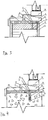
- Figure 3 is a horizontal view of the adjustment screw in use for supporting and adjusting a window having a bottom frame member 8.
- the stem 2a extends into a foundation of wood 10 and allows an external seal 9 to be fitted around the frame, and insulation 12 to be distributed evenly between the foundation 10 and the bottom frame member 8.
- Reference number 11 indicates external panelling. The invention thus provides for a better U-value than that of the prior art ( figure 1 ).
- the stem 2a extends into a plug 14 which has been inserted into a pre-drilled hole in a foundation of concrete 13. Similar to the configuration illustrated by figure 3 , the invention allows an external seal 9 to be fitted around the frame, and insulation 12 to be distributed evenly between the foundation 10 and the bottom frame member 8. The invention thus provides for a better U-value that that of the prior art ( figure 1 ).
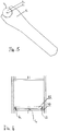
- FIG 5 illustrates an operating tool (or key) 15, connected to the octagonal edge 7 of the support plate 3.
- the operating tool 15 may easily be inserted between the bottom frame member 8 and the wood foundation 10 (or concrete foundation 13) and connected to the edge 7 even when the support plate 3 supports a frame. The height and/or level of the frame (and hence the window or door, etc.) may thus easily be adjusted.
- FIG 6 illustrates a method of using the adjustment screw.
- Adjustment screws 1a-c are fastened to the wood foundation 10, e.g. by means of a driving bit connected to the interface 4 (see figure 2 ).
- one screw 1a,b is positioned at each reveal (corner) and one screw 1c in the middle.
- the first screw 1a is adjusted to the desired level, e.g. by using the distance indicators 15.
- a second screws 1b is installed, a level 19 is placed on top of the screws' support plates 3, and each adjustment screw 1a-c is adjusted (by the tool 15; see figure 5 ) until the level is correct.
- the window or door may then be installed in a level frame.
Description
- The invention concerns an adjustable support device which with suitable accessories may be used for adjusting the height, level and sideways clearance when installing windows and doors in various building constructions. More specifically, the invention concerns an adjustable support device for a frame member, comprising a stem having fastening means for releasably connecting the stem to a foundation, and the adjustable support device also comprising a support element for the frame member, connected to one end of the stem, and a method of supporting and adjusting a frame member with respect to a foundation, by using at least two adjustable support devices according to the invention.
- Installing window frames and door frames in building constructions such that they are level, is a time consuming and cumbersome task. Especially when the foundation onto which the frame is to be installed is slanting and not level. This is in fact a very common situation where the foundation is a brick wall or a cast wall, and in particular in older buildings which are being refurbished.
- The state of the art involves using wedges made of wood or plastic as frame supports and adjustment means, an example of which is illustrated in
figure 1 . Thewedges 17 are inserted towards each other, one from each side of thebottom frame member 8 frame or side frame members 18 of thewindow 16, and pushed towards each other until the desired height adjustment and level has been obtained. Thewedges 17 are normally fixed by a nail, extending through the wedges and into thefoundation 10. If the wedges are too long, compared to the width of the foundation, they must be cut following installation. Each assembly ofwedges 17 occupies a significant volume between the foundation and the frame; these volumes cannot be insulated and are hence in effect thermal bridges in the finished building construction. This gives a higher U-value (a measure of the rate of heat loss through a material) than what is desired. - The state of the art includes NO 315431, which discloses an adjustable fastener for joining a window frame to a surrounding stationary building structure. The fastener comprises an externally threaded bushing which is designed to be screwed into a pre-drilled hole through the frame. A combined fastening and support screw fits inside the bushing, and the frame may thus be levelled by rotating the screw.
NO 142823 DE 7128103 andEP 0878591 all disclose fasteners for door frames. Further prior art is disclosed inGB 2131113 A EP 899407 A1 - The known means for installing and adjusting (e.g. levelling) window frames and door frames are cumbersome and time-consuming in use, some require pre-drilled holes, and others create unwanted thermal bridges.
The present applicant has devised and embodied this invention in order to overcome these shortcomings and to obtain further advantages. - The invention is set forth and characterized in the main claim, while the dependent claims describe other characteristics of the invention.
- It is thus provided an adjustable support device for a frame member, comprising a stem having fastening means for releasably connecting the stem to a foundation, and the adjustable support device also comprising a support element for the frame member, connected to one end of the stem. The adjustable support device is characterized by a tool interface portion which is accessible for an operating tool when the frame member is resting on the support element and configured such that the distance between the foundation and the frame member may be adjusted by the operating tool when a frame member is resting on the support element.
- In one embodiment, the tool interface portion comprises at least one pair of parallel, opposing faces which are configured for connection to the operating tool.
- In one embodiment, the support element is a plate member and the tool interface portion is arranged on an edge of the plate member. The adjustable support device preferably comprises distance indication means for indicating the distance between the foundation and the frame member. The distance indication means are in one embodiment markings at regular intervals on the stem.
- In one embodiment, the support element comprises a recessed portion configured for connection to a screw driver, bit or similar, and the recessed portion is arranged in the part of the support element which is configured for abutting against the frame member.
- It is also provided a method of supporting and adjusting a frame member with respect to a foundation, by using at least two adjustable support devices according to the invention, characterized by the steps of:
- a) installing a first adjustable support device by screwing or inserting its stem a desired distance into the foundation by using the distance indication means.
- b) installing a second adjustable support device by screwing or inserting its stem a distance into the foundation by using the distance indication means.
- c) placing a level gauge on top of the support plates of the first and second adjustable support devices;
- d) adjusting the distance between the foundation and the support element of the second adjustable support device until the correct level has been achieved.
- The invention makes it possible to adjust the height of the adjustable support device with respect to the support even when a frame is resting on the support element.
- These and other characteristics of the invention will be clear from the following description of a preferential form of embodiment, given as a non-restrictive example, with reference to the attached drawings wherein:
-
Figure 1 illustrates prior art support and adjustment devices for a window frame; -
Figure 2 is a perspective view of an embodiment of the adjustable support device according to the invention; -
Figure 3 is horizontal cross-sectional drawing showing the adjustable support device as illustrated infigure 2 , in use underneath a window frame in a foundation of wood; -
Figure 4 is horizontal cross-sectional drawing showing the adjustable support device as illustrated infigure 2 , in use underneath a window frame in a foundation of concrete; -
Figure 5 shows a tool configured for operating the embodiment of the adjustable support device shown infigure 2 ; and -
Figure 6 illustrates a method of levelling a frame by using the adjustable support device according to the invention. -
Figure 2 is a perspective view of an embodiment of the adjustable support device 1 according to the invention. The device, which in the following also will be referred to as an adjustment screw 1, comprises a stem 2a with external threads 1b and apointed end 6. The stem is dimensioned for the weight which the screw is intended to carry and configured for connection to the applicable foundation. The materials of the foundation may typically be wood, Siporex, metal, Leca ("Light Expanded Clay Aggregate"), brick or concrete. - The adjustment screw 1 furthermore comprises a
support plate 3 and aninterface portion 4 for a screw driver (not shown) or similar. Infigure 1 , theinterface portion 4 is in the form of a recessed hexagonal receptacle for a bit or screw driver. - The
support plate 3 comprises anedge 7 configured for interface with a suitable operating tool 15 (seefigure 5 ); the figures illustrating anoctagonal edge 7 having pairs of parallel and opposing faces 7a. Thesupport plate 3 is dimensioned according to relevant weight and surface area requirements. - The upper part of the stem 2a comprises distance indicator markings 5, whereby the operator visually may verify the height of the support plate, i.e. its distance from the foundation.
-
Figure 3 is a horizontal view of the adjustment screw in use for supporting and adjusting a window having abottom frame member 8. The stem 2a extends into a foundation ofwood 10 and allows an external seal 9 to be fitted around the frame, andinsulation 12 to be distributed evenly between thefoundation 10 and thebottom frame member 8.Reference number 11 indicates external panelling. The invention thus provides for a better U-value than that of the prior art (figure 1 ). - In
figure 4 , the stem 2a extends into aplug 14 which has been inserted into a pre-drilled hole in a foundation ofconcrete 13. Similar to the configuration illustrated byfigure 3 , the invention allows an external seal 9 to be fitted around the frame, andinsulation 12 to be distributed evenly between thefoundation 10 and thebottom frame member 8. The invention thus provides for a better U-value that that of the prior art (figure 1 ). -
Figure 5 illustrates an operating tool (or key) 15, connected to theoctagonal edge 7 of thesupport plate 3. Referring again tofigures 3 and 4 , it is understood that theoperating tool 15 may easily be inserted between thebottom frame member 8 and the wood foundation 10 (or concrete foundation 13) and connected to theedge 7 even when thesupport plate 3 supports a frame. The height and/or level of the frame (and hence the window or door, etc.) may thus easily be adjusted. -
Figure 6 illustrates a method of using the adjustment screw. Adjustment screws 1a-c are fastened to thewood foundation 10, e.g. by means of a driving bit connected to the interface 4 (seefigure 2 ). Preferably, one screw 1a,b is positioned at each reveal (corner) and one screw 1c in the middle. The first screw 1a is adjusted to the desired level, e.g. by using thedistance indicators 15. A second screws 1b is installed, alevel 19 is placed on top of the screws'support plates 3, and each adjustment screw 1a-c is adjusted (by thetool 15; seefigure 5 ) until the level is correct. The window or door may then be installed in a level frame.
Claims (6)
- An adjustable support device (1) for a frame member (8), comprising a stem (2a) having fastening means (2b, 6) for releasably connecting the stem to a foundation (10, 13), and the adjustable support device also comprising a support element (3) for the frame member, connected to one end of the stem, the adjustable support device (1) further comprising a tool interface portion (7) which is accessible for an operating tool (15) when the frame member is resting on the support element (3) and configured such that the distance between the foundation and the frame member may be adjusted by the operating tool when a frame member is resting on the support element,
characterized in that the upper part of the stem (2a) further comprises distance indication means (5) arranged between the fastening means (2b, 6) and the support element (3) for indicating a desired distance between the foundation and the frame when the frame is placed on the support element. - The adjustable support device according to claim 1, wherein the tool interface portion (7) comprises at least one pair of parallel, opposing faces (7a) which are configured for connection to the operating tool (15).
- The adjustable support device according to claim 1 or claim 2, wherein the support element (3) is a plate member and the tool interface portion (7) is arranged on an edge of the plate member.
- The adjustable support device according to claim 1, wherein the distance indication means (5) comprise markings at regular intervals on the stem.
- The adjustable support device according to any one of the preceding claims, wherein the support element comprises a recessed portion (4) configured for connection to a screw driver, bit or similar, and the recessed portion is arranged in the part of the support element which is configured for abutting against the frame member.
- A method of supporting and adjusting a frame member (8) with respect to a foundation (10, 13) by using at least two adjustable support devices (1a, 1b) according to any one of claims 1-5,
characterized in that the method comprises the steps of:a) installing a first adjustable support device (1a) by screwing or inserting its stem a desired distance into the foundation by using the distance indication means (5);b) installing a second adjustable support device (1b) by screwing or inserting its stem the distance into the foundation by using the distance indication means (5);c) placing a level (19) on top of the support plates (3) of the first and second adjustable support devices;d) adjusting the distance between the foundation (10, 13) and the support element (3) of the adjustable support devices (1a, 1b) until the correct level has been achieved.
Applications Claiming Priority (1)
| Application Number | Priority Date | Filing Date | Title |
|---|---|---|---|
| PCT/EP2012/054026 WO2013131572A1 (en) | 2012-03-08 | 2012-03-08 | Adjustable support device for a frame member and installation method |
Publications (2)
| Publication Number | Publication Date |
|---|---|
| EP2834440A1 EP2834440A1 (en) | 2015-02-11 |
| EP2834440B1 true EP2834440B1 (en) | 2017-05-03 |
Family
ID=45812781
Family Applications (1)
| Application Number | Title | Priority Date | Filing Date |
|---|---|---|---|
| EP12708019.0A Active EP2834440B1 (en) | 2012-03-08 | 2012-03-08 | Adjustable support device for a frame member and installation method |
Country Status (5)
| Country | Link |
|---|---|
| US (1) | US20150075091A1 (en) |
| EP (1) | EP2834440B1 (en) |
| CN (1) | CN104302860A (en) |
| CA (1) | CA2903902C (en) |
| WO (1) | WO2013131572A1 (en) |
Families Citing this family (2)
| Publication number | Priority date | Publication date | Assignee | Title |
|---|---|---|---|---|
| CN104712220B (en) * | 2015-03-19 | 2017-03-08 | 常州玖洲联横建材有限公司 | A kind of auxiliary frame connector and its installation method |
| CN113417542B (en) * | 2021-07-16 | 2022-05-03 | 北京建筑大学 | Double-layer window suitable for protecting historical buildings |
Citations (6)
| Publication number | Priority date | Publication date | Assignee | Title |
|---|---|---|---|---|
| GB2131113A (en) | 1982-11-25 | 1984-06-13 | Chang Chung Hsing | Bolt driving formation |
| US4856241A (en) | 1985-09-09 | 1989-08-15 | Lars Lagergren | Device for fastening doors and windows to a wall opening |
| KR100762784B1 (en) | 2007-01-08 | 2007-10-02 | (주)좋은문 | Apparatus for fixing a doorframe |
| US20100209213A1 (en) | 2009-02-17 | 2010-08-19 | Savio S.P.A. | System for fastening accessories on frames made of metal material for doors, windows, and the like |
| CN201775689U (en) | 2010-08-23 | 2011-03-30 | 阎京如 | Artificial dental implant |
| US20110112436A1 (en) | 2009-11-06 | 2011-05-12 | SpineSmith Partners, LP | Distraction pins for fluid aspiration |
Family Cites Families (26)
| Publication number | Priority date | Publication date | Assignee | Title |
|---|---|---|---|---|
| DE7128103U (en) | 1971-10-28 | Fitzner A | Fastening device for block chucks, in particular for door frames | |
| US2764886A (en) * | 1951-04-10 | 1956-10-02 | Robertson Co H H | Identification device for the wiring cells of a floor |
| US2940784A (en) * | 1956-06-06 | 1960-06-14 | William B Fell | Precision threaded adjustment |
| IT1035892B (en) * | 1974-06-05 | 1979-10-20 | Hulinsky J | DEVICE AND PROCEDURE FOR FIXING FRAMES OF DOORS AND WINDOWS |
| US4450834A (en) * | 1979-10-18 | 1984-05-29 | Ace Orthopedic Manufacturing, Inc. | External fixation device |
| US4397124A (en) * | 1981-06-10 | 1983-08-09 | Kawneer Company, Inc. | Glass jacks for doors, windows, walls, etc. |
| US4635414A (en) * | 1982-09-15 | 1987-01-13 | Allen Ernest R | Adjustable door jamb leveler |
| US5180388A (en) * | 1990-06-28 | 1993-01-19 | American Cyanamid Company | Bone pinning system |
| US5511760A (en) * | 1993-11-02 | 1996-04-30 | Kambara; Goro | Post installable self locking machine leveling device |
| DE19720879A1 (en) | 1997-05-17 | 1998-11-19 | Wuerth Adolf Gmbh & Co Kg | Device for fastening a wooden element |
| US5895389A (en) * | 1997-05-29 | 1999-04-20 | Synthes (U.S.A.) | Drilling guide and measuring instrumentation |
| EP0899407A1 (en) * | 1997-09-01 | 1999-03-03 | GLUSA, Dieter | Support and fastening device for fastening the frame of a window or door in the wall opening of a building |
| US6308476B1 (en) * | 1998-08-25 | 2001-10-30 | Kabushiki Kaisha Juken Sangyo | Adjustable frame |
| US6185870B1 (en) * | 1999-08-06 | 2001-02-13 | Stafast Products, Inc. | Adjustable threshold assembly |
| DE19948543A1 (en) * | 1999-09-22 | 2001-04-26 | Andreas Stroeber | Method for aligning window frame in wall opening uses self threaded aligning bolts with external self tapping thread fitted through the frame and onto wall supports |
| DE10202029A1 (en) * | 2002-01-18 | 2003-07-24 | Bayerwald Fenster Und Haustuer | Lock installation system for house and balcony doors includes adjustment mechanisms setting height of door frame and position in two horizontal planes |
| US6951562B2 (en) * | 2002-11-13 | 2005-10-04 | Ralph Fritz Zwirnmann | Adjustable length tap and method for drilling and tapping a bore in bone |
| US7210382B2 (en) * | 2005-08-15 | 2007-05-01 | Eastway Fair Company Ltd. | Screw guide device |
| US7987637B2 (en) * | 2006-09-25 | 2011-08-02 | Smith Patrick J | Adjustable shim |
| US7481253B2 (en) * | 2006-10-02 | 2009-01-27 | Woodpeckers, Inc. | Adjustable scale and router table for use therewith |
| US20100257789A1 (en) * | 2009-04-09 | 2010-10-14 | Quanex Building Products Corporation | Seal for an adjustable threshold assembly |
| DE202009015144U1 (en) * | 2009-11-06 | 2010-03-18 | Weber, Josef | screwing |
| NZ574949A (en) * | 2010-01-12 | 2011-04-29 | Pranesh Kumar | Cannulated surgical drill with depth gauge |
| US8806812B2 (en) * | 2010-01-27 | 2014-08-19 | Black Mountain Door, Llc | Adjustable door frame assembly and method of installation |
| US9308080B2 (en) * | 2010-03-10 | 2016-04-12 | Smith & Nephew Inc. | Composite interference screws and drivers |
| JP5855925B2 (en) * | 2011-12-13 | 2016-02-09 | 株式会社屋根技術研究所 | Supporting roof tile |
-
2012
- 2012-03-08 WO PCT/EP2012/054026 patent/WO2013131572A1/en active Application Filing
- 2012-03-08 CN CN201280071276.8A patent/CN104302860A/en active Pending
- 2012-03-08 EP EP12708019.0A patent/EP2834440B1/en active Active
- 2012-03-08 CA CA2903902A patent/CA2903902C/en active Active
- 2012-03-08 US US14/382,556 patent/US20150075091A1/en not_active Abandoned
Patent Citations (6)
| Publication number | Priority date | Publication date | Assignee | Title |
|---|---|---|---|---|
| GB2131113A (en) | 1982-11-25 | 1984-06-13 | Chang Chung Hsing | Bolt driving formation |
| US4856241A (en) | 1985-09-09 | 1989-08-15 | Lars Lagergren | Device for fastening doors and windows to a wall opening |
| KR100762784B1 (en) | 2007-01-08 | 2007-10-02 | (주)좋은문 | Apparatus for fixing a doorframe |
| US20100209213A1 (en) | 2009-02-17 | 2010-08-19 | Savio S.P.A. | System for fastening accessories on frames made of metal material for doors, windows, and the like |
| US20110112436A1 (en) | 2009-11-06 | 2011-05-12 | SpineSmith Partners, LP | Distraction pins for fluid aspiration |
| CN201775689U (en) | 2010-08-23 | 2011-03-30 | 阎京如 | Artificial dental implant |
Also Published As
| Publication number | Publication date |
|---|---|
| US20150075091A1 (en) | 2015-03-19 |
| CA2903902C (en) | 2017-11-14 |
| CN104302860A (en) | 2015-01-21 |
| EP2834440A1 (en) | 2015-02-11 |
| WO2013131572A1 (en) | 2013-09-12 |
| CA2903902A1 (en) | 2013-09-12 |
Similar Documents
| Publication | Publication Date | Title |
|---|---|---|
| US7908804B2 (en) | Structural lintel assembly and building construction method using the same | |
| US8826629B1 (en) | Apparatus and method for an adjustable column | |
| US20180320384A1 (en) | Cladding System | |
| US6231025B1 (en) | Ready-mixed concrete placing method and formwork unit used for the method | |
| EA010805B1 (en) | Insulated concrete form system with variable length wall ties | |
| EP2261430A2 (en) | Constructing an overhang | |
| EP2834440B1 (en) | Adjustable support device for a frame member and installation method | |
| US20140352241A1 (en) | Dynamic Concrete Form | |
| KR102100751B1 (en) | An exterior material fixing device for constructing the exterior material on the building | |
| KR102100754B1 (en) | Wedge type of exterior material fixing device for constructing the exterior material on the outer wall surface of the building | |
| KR20100027628A (en) | Wall panels of a prefabricated bathroom | |
| AU2016256678A2 (en) | Creation of Surface-Mounted Sills or Hobs on Cast-in-situ Concrete Building Slabs | |
| KR101966138B1 (en) | The supporter for concrete forms of slab | |
| CN204252509U (en) | A kind of construction of lift well operation frame | |
| KR200493277Y1 (en) | Low support bracket of sliding patio window | |
| CN104234401A (en) | Construction operation frame for elevator shaft | |
| US20170254070A1 (en) | Wall Construction | |
| EP3134586B1 (en) | Device and method for anchoring an overhanging element to a construction | |
| US20230058151A1 (en) | Cladded Wall System | |
| CA2602767C (en) | Structural lintel assembly and building construction method using the same | |
| KR200415831Y1 (en) | Height and horizontality adjustable apparatus of panel | |
| WO2009033251A1 (en) | Structural lintel assembly and building construction method using the same | |
| KR101698383B1 (en) | Finish material support apparatus and construction method of brick wall using the same | |
| CA3083633A1 (en) | A pour stop | |
| KR101187434B1 (en) | Height adjustable device for perfabricated form panel using plate combined with bolt |
Legal Events
| Date | Code | Title | Description |
|---|---|---|---|
| PUAI | Public reference made under article 153(3) epc to a published international application that has entered the european phase |
Free format text: ORIGINAL CODE: 0009012 |
|
| 17P | Request for examination filed |
Effective date: 20141001 |
|
| AK | Designated contracting states |
Kind code of ref document: A1 Designated state(s): AL AT BE BG CH CY CZ DE DK EE ES FI FR GB GR HR HU IE IS IT LI LT LU LV MC MK MT NL NO PL PT RO RS SE SI SK SM TR |
|
| AX | Request for extension of the european patent |
Extension state: BA ME |
|
| DAX | Request for extension of the european patent (deleted) | ||
| REG | Reference to a national code |
Ref country code: DE Ref legal event code: R079 Ref document number: 602012031879 Country of ref document: DE Free format text: PREVIOUS MAIN CLASS: E06B0001600000 Ipc: E06B0001040000 |
|
| GRAP | Despatch of communication of intention to grant a patent |
Free format text: ORIGINAL CODE: EPIDOSNIGR1 |
|
| RIC1 | Information provided on ipc code assigned before grant |
Ipc: E06B 7/00 20060101ALI20161019BHEP Ipc: E06B 1/60 20060101ALI20161019BHEP Ipc: E06B 1/04 20060101AFI20161019BHEP |
|
| INTG | Intention to grant announced |
Effective date: 20161110 |
|
| GRAS | Grant fee paid |
Free format text: ORIGINAL CODE: EPIDOSNIGR3 |
|
| GRAA | (expected) grant |
Free format text: ORIGINAL CODE: 0009210 |
|
| AK | Designated contracting states |
Kind code of ref document: B1 Designated state(s): AL AT BE BG CH CY CZ DE DK EE ES FI FR GB GR HR HU IE IS IT LI LT LU LV MC MK MT NL NO PL PT RO RS SE SI SK SM TR |
|
| REG | Reference to a national code |
Ref country code: GB Ref legal event code: FG4D |
|
| REG | Reference to a national code |
Ref country code: AT Ref legal event code: REF Ref document number: 890193 Country of ref document: AT Kind code of ref document: T Effective date: 20170515 Ref country code: CH Ref legal event code: EP |
|
| REG | Reference to a national code |
Ref country code: IE Ref legal event code: FG4D |
|
| REG | Reference to a national code |
Ref country code: DE Ref legal event code: R096 Ref document number: 602012031879 Country of ref document: DE |
|
| REG | Reference to a national code |
Ref country code: SE Ref legal event code: TRGR |
|
| REG | Reference to a national code |
Ref country code: NL Ref legal event code: MP Effective date: 20170503 |
|
| REG | Reference to a national code |
Ref country code: LT Ref legal event code: MG4D |
|
| REG | Reference to a national code |
Ref country code: NO Ref legal event code: T2 Effective date: 20170503 |
|
| PG25 | Lapsed in a contracting state [announced via postgrant information from national office to epo] |
Ref country code: ES Free format text: LAPSE BECAUSE OF FAILURE TO SUBMIT A TRANSLATION OF THE DESCRIPTION OR TO PAY THE FEE WITHIN THE PRESCRIBED TIME-LIMIT Effective date: 20170503 Ref country code: LT Free format text: LAPSE BECAUSE OF FAILURE TO SUBMIT A TRANSLATION OF THE DESCRIPTION OR TO PAY THE FEE WITHIN THE PRESCRIBED TIME-LIMIT Effective date: 20170503 Ref country code: GR Free format text: LAPSE BECAUSE OF FAILURE TO SUBMIT A TRANSLATION OF THE DESCRIPTION OR TO PAY THE FEE WITHIN THE PRESCRIBED TIME-LIMIT Effective date: 20170804 Ref country code: HR Free format text: LAPSE BECAUSE OF FAILURE TO SUBMIT A TRANSLATION OF THE DESCRIPTION OR TO PAY THE FEE WITHIN THE PRESCRIBED TIME-LIMIT Effective date: 20170503 |
|
| PG25 | Lapsed in a contracting state [announced via postgrant information from national office to epo] |
Ref country code: NL Free format text: LAPSE BECAUSE OF FAILURE TO SUBMIT A TRANSLATION OF THE DESCRIPTION OR TO PAY THE FEE WITHIN THE PRESCRIBED TIME-LIMIT Effective date: 20170503 Ref country code: LV Free format text: LAPSE BECAUSE OF FAILURE TO SUBMIT A TRANSLATION OF THE DESCRIPTION OR TO PAY THE FEE WITHIN THE PRESCRIBED TIME-LIMIT Effective date: 20170503 Ref country code: RS Free format text: LAPSE BECAUSE OF FAILURE TO SUBMIT A TRANSLATION OF THE DESCRIPTION OR TO PAY THE FEE WITHIN THE PRESCRIBED TIME-LIMIT Effective date: 20170503 Ref country code: BG Free format text: LAPSE BECAUSE OF FAILURE TO SUBMIT A TRANSLATION OF THE DESCRIPTION OR TO PAY THE FEE WITHIN THE PRESCRIBED TIME-LIMIT Effective date: 20170803 Ref country code: IS Free format text: LAPSE BECAUSE OF FAILURE TO SUBMIT A TRANSLATION OF THE DESCRIPTION OR TO PAY THE FEE WITHIN THE PRESCRIBED TIME-LIMIT Effective date: 20170903 Ref country code: PL Free format text: LAPSE BECAUSE OF FAILURE TO SUBMIT A TRANSLATION OF THE DESCRIPTION OR TO PAY THE FEE WITHIN THE PRESCRIBED TIME-LIMIT Effective date: 20170503 |
|
| PG25 | Lapsed in a contracting state [announced via postgrant information from national office to epo] |
Ref country code: EE Free format text: LAPSE BECAUSE OF FAILURE TO SUBMIT A TRANSLATION OF THE DESCRIPTION OR TO PAY THE FEE WITHIN THE PRESCRIBED TIME-LIMIT Effective date: 20170503 Ref country code: RO Free format text: LAPSE BECAUSE OF FAILURE TO SUBMIT A TRANSLATION OF THE DESCRIPTION OR TO PAY THE FEE WITHIN THE PRESCRIBED TIME-LIMIT Effective date: 20170503 Ref country code: CZ Free format text: LAPSE BECAUSE OF FAILURE TO SUBMIT A TRANSLATION OF THE DESCRIPTION OR TO PAY THE FEE WITHIN THE PRESCRIBED TIME-LIMIT Effective date: 20170503 Ref country code: SK Free format text: LAPSE BECAUSE OF FAILURE TO SUBMIT A TRANSLATION OF THE DESCRIPTION OR TO PAY THE FEE WITHIN THE PRESCRIBED TIME-LIMIT Effective date: 20170503 Ref country code: DK Free format text: LAPSE BECAUSE OF FAILURE TO SUBMIT A TRANSLATION OF THE DESCRIPTION OR TO PAY THE FEE WITHIN THE PRESCRIBED TIME-LIMIT Effective date: 20170503 |
|
| REG | Reference to a national code |
Ref country code: DE Ref legal event code: R026 Ref document number: 602012031879 Country of ref document: DE |
|
| PLBI | Opposition filed |
Free format text: ORIGINAL CODE: 0009260 |
|
| PLAX | Notice of opposition and request to file observation + time limit sent |
Free format text: ORIGINAL CODE: EPIDOSNOBS2 |
|
| PG25 | Lapsed in a contracting state [announced via postgrant information from national office to epo] |
Ref country code: IT Free format text: LAPSE BECAUSE OF FAILURE TO SUBMIT A TRANSLATION OF THE DESCRIPTION OR TO PAY THE FEE WITHIN THE PRESCRIBED TIME-LIMIT Effective date: 20170503 Ref country code: SM Free format text: LAPSE BECAUSE OF FAILURE TO SUBMIT A TRANSLATION OF THE DESCRIPTION OR TO PAY THE FEE WITHIN THE PRESCRIBED TIME-LIMIT Effective date: 20170503 |
|
| 26 | Opposition filed |
Opponent name: VAESTSVENSK BYGGSKRUV AB Effective date: 20180205 |
|
| PG25 | Lapsed in a contracting state [announced via postgrant information from national office to epo] |
Ref country code: SI Free format text: LAPSE BECAUSE OF FAILURE TO SUBMIT A TRANSLATION OF THE DESCRIPTION OR TO PAY THE FEE WITHIN THE PRESCRIBED TIME-LIMIT Effective date: 20170503 |
|
| PLBB | Reply of patent proprietor to notice(s) of opposition received |
Free format text: ORIGINAL CODE: EPIDOSNOBS3 |
|
| PLBP | Opposition withdrawn |
Free format text: ORIGINAL CODE: 0009264 |
|
| PLBD | Termination of opposition procedure: decision despatched |
Free format text: ORIGINAL CODE: EPIDOSNOPC1 |
|
| REG | Reference to a national code |
Ref country code: DE Ref legal event code: R100 Ref document number: 602012031879 Country of ref document: DE |
|
| PLBM | Termination of opposition procedure: date of legal effect published |
Free format text: ORIGINAL CODE: 0009276 |
|
| STAA | Information on the status of an ep patent application or granted ep patent |
Free format text: STATUS: OPPOSITION PROCEDURE CLOSED |
|
| GBPC | Gb: european patent ceased through non-payment of renewal fee |
Effective date: 20180308 |
|
| PG25 | Lapsed in a contracting state [announced via postgrant information from national office to epo] |
Ref country code: MC Free format text: LAPSE BECAUSE OF FAILURE TO SUBMIT A TRANSLATION OF THE DESCRIPTION OR TO PAY THE FEE WITHIN THE PRESCRIBED TIME-LIMIT Effective date: 20170503 |
|
| 27C | Opposition proceedings terminated |
Effective date: 20180727 |
|
| REG | Reference to a national code |
Ref country code: BE Ref legal event code: MM Effective date: 20180331 |
|
| REG | Reference to a national code |
Ref country code: IE Ref legal event code: MM4A |
|
| PG25 | Lapsed in a contracting state [announced via postgrant information from national office to epo] |
Ref country code: LU Free format text: LAPSE BECAUSE OF NON-PAYMENT OF DUE FEES Effective date: 20180308 |
|
| PG25 | Lapsed in a contracting state [announced via postgrant information from national office to epo] |
Ref country code: IE Free format text: LAPSE BECAUSE OF NON-PAYMENT OF DUE FEES Effective date: 20180308 |
|
| PG25 | Lapsed in a contracting state [announced via postgrant information from national office to epo] |
Ref country code: GB Free format text: LAPSE BECAUSE OF NON-PAYMENT OF DUE FEES Effective date: 20180308 Ref country code: BE Free format text: LAPSE BECAUSE OF NON-PAYMENT OF DUE FEES Effective date: 20180331 |
|
| PG25 | Lapsed in a contracting state [announced via postgrant information from national office to epo] |
Ref country code: FR Free format text: LAPSE BECAUSE OF NON-PAYMENT OF DUE FEES Effective date: 20180331 |
|
| PG25 | Lapsed in a contracting state [announced via postgrant information from national office to epo] |
Ref country code: MT Free format text: LAPSE BECAUSE OF NON-PAYMENT OF DUE FEES Effective date: 20180308 |
|
| REG | Reference to a national code |
Ref country code: AT Ref legal event code: UEP Ref document number: 890193 Country of ref document: AT Kind code of ref document: T Effective date: 20170503 |
|
| PG25 | Lapsed in a contracting state [announced via postgrant information from national office to epo] |
Ref country code: TR Free format text: LAPSE BECAUSE OF FAILURE TO SUBMIT A TRANSLATION OF THE DESCRIPTION OR TO PAY THE FEE WITHIN THE PRESCRIBED TIME-LIMIT Effective date: 20170503 |
|
| PG25 | Lapsed in a contracting state [announced via postgrant information from national office to epo] |
Ref country code: PT Free format text: LAPSE BECAUSE OF FAILURE TO SUBMIT A TRANSLATION OF THE DESCRIPTION OR TO PAY THE FEE WITHIN THE PRESCRIBED TIME-LIMIT Effective date: 20170503 |
|
| PG25 | Lapsed in a contracting state [announced via postgrant information from national office to epo] |
Ref country code: MK Free format text: LAPSE BECAUSE OF NON-PAYMENT OF DUE FEES Effective date: 20170503 Ref country code: CY Free format text: LAPSE BECAUSE OF FAILURE TO SUBMIT A TRANSLATION OF THE DESCRIPTION OR TO PAY THE FEE WITHIN THE PRESCRIBED TIME-LIMIT Effective date: 20170503 Ref country code: HU Free format text: LAPSE BECAUSE OF FAILURE TO SUBMIT A TRANSLATION OF THE DESCRIPTION OR TO PAY THE FEE WITHIN THE PRESCRIBED TIME-LIMIT; INVALID AB INITIO Effective date: 20120308 |
|
| PG25 | Lapsed in a contracting state [announced via postgrant information from national office to epo] |
Ref country code: AL Free format text: LAPSE BECAUSE OF FAILURE TO SUBMIT A TRANSLATION OF THE DESCRIPTION OR TO PAY THE FEE WITHIN THE PRESCRIBED TIME-LIMIT Effective date: 20170503 |
|
| PGFP | Annual fee paid to national office [announced via postgrant information from national office to epo] |
Ref country code: DE Payment date: 20220322 Year of fee payment: 11 Ref country code: CH Payment date: 20220321 Year of fee payment: 11 Ref country code: AT Payment date: 20220322 Year of fee payment: 11 |
|
| REG | Reference to a national code |
Ref country code: FI Ref legal event code: PCE Owner name: NESBOE, PAUL ARNE |
|
| REG | Reference to a national code |
Ref country code: NO Ref legal event code: CHAD Owner name: PAUL ARNE NESBOE, NO |
|
| PGFP | Annual fee paid to national office [announced via postgrant information from national office to epo] |
Ref country code: NO Payment date: 20230118 Year of fee payment: 12 Ref country code: FI Payment date: 20230220 Year of fee payment: 12 |
|
| PGFP | Annual fee paid to national office [announced via postgrant information from national office to epo] |
Ref country code: SE Payment date: 20230210 Year of fee payment: 12 |
|
| REG | Reference to a national code |
Ref country code: DE Ref legal event code: R119 Ref document number: 602012031879 Country of ref document: DE |
|
| REG | Reference to a national code |
Ref country code: CH Ref legal event code: PL |
|
| REG | Reference to a national code |
Ref country code: AT Ref legal event code: MM01 Ref document number: 890193 Country of ref document: AT Kind code of ref document: T Effective date: 20230308 |
|
| PG25 | Lapsed in a contracting state [announced via postgrant information from national office to epo] |
Ref country code: LI Free format text: LAPSE BECAUSE OF NON-PAYMENT OF DUE FEES Effective date: 20230331 Ref country code: DE Free format text: LAPSE BECAUSE OF NON-PAYMENT OF DUE FEES Effective date: 20231003 Ref country code: CH Free format text: LAPSE BECAUSE OF NON-PAYMENT OF DUE FEES Effective date: 20230331 Ref country code: AT Free format text: LAPSE BECAUSE OF NON-PAYMENT OF DUE FEES Effective date: 20230308 |