EP4134483B1 - Kleidungspflegemaschine - Google Patents
Kleidungspflegemaschine Download PDFInfo
- Publication number
- EP4134483B1 EP4134483B1 EP22180010.5A EP22180010A EP4134483B1 EP 4134483 B1 EP4134483 B1 EP 4134483B1 EP 22180010 A EP22180010 A EP 22180010A EP 4134483 B1 EP4134483 B1 EP 4134483B1
- Authority
- EP
- European Patent Office
- Prior art keywords
- water tank
- pin
- water
- sleeve
- clothing care
- Prior art date
- Legal status (The legal status is an assumption and is not a legal conclusion. Google has not performed a legal analysis and makes no representation as to the accuracy of the status listed.)
- Active
Links
Images






Classifications
-
- D—TEXTILES; PAPER
- D06—TREATMENT OF TEXTILES OR THE LIKE; LAUNDERING; FLEXIBLE MATERIALS NOT OTHERWISE PROVIDED FOR
- D06F—LAUNDERING, DRYING, IRONING, PRESSING OR FOLDING TEXTILE ARTICLES
- D06F87/00—Apparatus for moistening or otherwise conditioning the article to be ironed or pressed
-
- D—TEXTILES; PAPER
- D06—TREATMENT OF TEXTILES OR THE LIKE; LAUNDERING; FLEXIBLE MATERIALS NOT OTHERWISE PROVIDED FOR
- D06F—LAUNDERING, DRYING, IRONING, PRESSING OR FOLDING TEXTILE ARTICLES
- D06F58/00—Domestic laundry dryers
- D06F58/10—Drying cabinets or drying chambers having heating or ventilating means
- D06F58/14—Collapsible drying cabinets; Wall mounted collapsible hoods
-
- D—TEXTILES; PAPER
- D06—TREATMENT OF TEXTILES OR THE LIKE; LAUNDERING; FLEXIBLE MATERIALS NOT OTHERWISE PROVIDED FOR
- D06F—LAUNDERING, DRYING, IRONING, PRESSING OR FOLDING TEXTILE ARTICLES
- D06F73/00—Apparatus for smoothing or removing creases from garments or other textile articles by formers, cores, stretchers, or internal frames, with the application of heat or steam
- D06F73/02—Apparatus for smoothing or removing creases from garments or other textile articles by formers, cores, stretchers, or internal frames, with the application of heat or steam having one or more treatment chambers
Definitions
- the present invention relates to the field of daily life, and in particular, to a clothing care machine.
- the present invention provides a clothing care machine in order to solve the above problems.
- the lower end of the connecting rod is connected with a fitting piece provided with a guide hole;
- the fixing block is provided with a guide post penetrating into the guide hole, and the fixing block forms an oblique guide fit with the elastic pin through the fitting piece.
- the elastic pin comprises a spring and a pin body
- the fixing block is provided with a blind hole
- the spring and the pin body are inserted in the blind hole; when the spring exerts an outward elastic force on the pin body, an outer end of the pin body is protruded with the pin mated with the pin hole.
- the upper part is provided with a button, the upper end of the connecting rod abuts the button, and the connecting rod is pressed down by pressing the button.
- the fixing assembly further comprises an elastic adjusting unit comprising a movable abutting block and a cam; the lower sleeve is provided with a receiving opening, the movable abutting block is provided in the receiving opening; the cam is provided with a hinge and located outside the movable abutting block, such that the movable abutting block is located between the cam and the upper sleeve.
- an elastic adjusting unit comprising a movable abutting block and a cam
- the lower sleeve is provided with a receiving opening
- the movable abutting block is provided in the receiving opening
- the cam is provided with a hinge and located outside the movable abutting block, such that the movable abutting block is located between the cam and the upper sleeve.
- the upper part is provided with a support frame provided with a support rod, and the support rod is provided with a clamping piece.
- two side surfaces of the support rod are concave surfaces;
- the clamping piece comprises a clamping body and a hanging lug extending from the clamping body, the hanging lug and the clamping body are enclosed to form a through hole, the support rod penetrates into the through hole to have a connection between the support rod and the clamping piece; one side wall of the hanging lug is inwardly recessed and mated with one side concave surface of the support rod.
- two ends of the support rod are respectively connected with end covers, and are detachably assembled on the top seat through the end covers; and the support rod is detachably connected to at least one of the end covers.
- the machine base is provided with a water tank, a heating and vaporizing boiler, a condensed water collector and a switch valve; a water outlet of the water tank is connected to a water inlet of the heating and vaporizing boiler, an outlet of the heating and vaporizing boiler is connected to the steam opening; the condensed water collector is disposed on the machine base for collecting condensed water, and a water outlet of the condensed water collector is in communication with a water inlet of the water tank through a recovery channel, the switch valve is provided in the recovery channel; the water tank is detachably provided on the machine base, and the switch valve is triggered to open when the water tank is assembled.
- an upper end of the water tank has an inclined abutting surface
- an outside of the machine base is recessed with a water tank receiving cavity
- a trigger end of the switch valve extends into the water tank receiving cavity through a top of the water tank receiving cavity; when the water tank is assembled into the water tank receiving cavity, the inclined abutting surface abuts the trigger end of the switch valve and the switch valve is triggered to be activated.
- the water outlet of the water tank is a normally closed water outlet
- the water tank receiving cavity is provided with a butt joint at a bottom of the water tank receiving cavity; when the water tank is assembled into the water tank receiving cavity, the butt joint cooperates with the water outlet of the water tank to open the water outlet of the water tank.
- a water pump is provided between the water tank and the heating and vaporizing boiler; water in the water tank is pumped into the heating and vaporizing boiler through the water pump.
- the clothes are hung on the upper part, and the automatic care of the clothes is realized through the steam output by the steam opening of the machine base and/or the hot air output by the hot air opening.
- the user does not need to operate the whole process, such that time and effort can be saved.
- the present embodiment provides a clothing care machine, including a machine base 10, a support column 20, a cloth cover 40 and an upper part.
- the bottom of the support column 20 may be connected to the machine base 10.
- the upper part may be a substantially rectangular top seat 30 connected to the top of the support column 20, and the cloth cover 40 may be provided between the machine base 10 and the top seat 30 to form an enclosed cavity.
- the machine base 10 may be provided with a steam opening 11 and a hot air opening 19 in communication with the enclosed cavity. When in use, the clothes are put into the enclosed cavity, and the automatic care of the clothes is realized through the cooperation of the steam output by the steam opening 11 and the hot air output by the hot air opening 19 of the machine base 10.
- the combination of the steam output from the steam opening 11 and the hot air output from the hot air opening 19 may be independent outputs or alternate outputs (e.g., steam output first, then hot air output, etc.).
- the user does not need to operate the whole process, but only needs to put the clothes in and out, such that time and effort can be saved.
- the clothing care machine provided in the present embodiment is a rectangle from a top view.
- the long side direction is defined as a left-right direction
- the short side direction is defined as a front-rear direction.
- the shape of the clothing care machine is not limited to this.
- the cloth cover 40 may be provided with a zipper 401, and the cloth cover 40 is opened and closed through the zipper 401 for taking and placing clothes into the enclosed cavity.
- the support column 20 may be a retractable structure. In this way, through the retracting of the support column 20, the clothing care machine can be stored, and the volume after storage is small and does not occupy space.
- the support column 20 can also be a fixed structure without retracting.
- the retractable structure of the support column 20 may be as follows: the support column 20 includes an upper sleeve 21 and a lower sleeve 22 that are telescopically sleeved, the lower end of the lower sleeve 22 is connected to the machine base 10, and the upper end of the upper sleeve 21 is connected to the top seat 30; a fixing assembly for fixing the relative positions of the upper sleeve 21 and the lower sleeve 22 is provided between the upper sleeve 21 and the lower sleeve 22. During use, the upper sleeve 21 and the lower sleeve 22 are fixed by the fixing assembly to obtain a stable support.
- the support column 20 When the support column 20 needs to be stored, the support column 20 can be retracted by releasing the fixing of the fixing assembly. At the same time, the use of the sleeve structure of the sleeve can reduce the weight very well.
- the retractable structure of the support column 20 is not limited to this.
- the fixing assembly includes a pin fixing unit 23 and a tension adjusting unit, wherein the pin fixing unit 23 may be fixed on one side, and the tension adjusting unit may be fixed on the other side.
- the pin fixing unit 23 may include: a fixing block 234, an elastic pin 231 and a connecting rod 232.
- the fixing block 234 may be fixed in the lower opening of the upper sleeve 21, and the elastic pin 231 may be provided on the fixing block 234.
- the lower sleeve 22 may be provided with a pin hole 221 corresponding to the elastic pin 231. Under the action of no external force, the pin 2313 of the elastic pin 231 protrudes and is inserted into the corresponding pin hole 221 to make the relative positions of the upper sleeve 21 and the lower sleeve 22 fixed, such that the support column 20 can be fixedly supported.
- the connecting rod 232 may be provided in the upper sleeve 21, and the lower end of the connecting rod 232 forms an oblique guide fit with the elastic pin 231.
- the upper end of the connecting rod 232 extends to the top seat 30.
- the connecting rod 232 can be driven to be pressed down to drive the elastic pin 231 to retract. That is, when it is necessary to release the fixation of the pin fixing unit 23, the connecting rod 232 is pressed down, and the downward movement of the connecting rod 232 drives the elastic pin 231 to retract through the inclined guide fit structure, such that the pin 2313 of the elastic pin 231 is separated from the pin hole 221, such that the fixing of the pin fixing unit 23 is released.
- the lower end of the connecting rod 232 may be connected with a fitting piece 233 and forms an oblique guide fit with the elastic pin 231 through the fitting piece 233, which is convenient for connecting and fitting.
- the fitting piece 233 may be provided with a guide hole (not shown), and the fixing block 234 may be provided with a guide post 2341.
- the guide post 2341 penetrates into the guide hole to realize the guide fit, such that the fit is more precise and smoother and not easy to shift or clamp.
- the elastic pin 231 may include a spring 2312 and a pin body 2311, and a blind hole 2342 may be formed on the fixing block 234.
- the spring 2312 and the pin body 2311 may be inserted into the blind hole 2342, and the spring 2312 applies an outward elastic force to the pin body 2311.
- the outer end of the pin body 2311 protrudes with the pin 2313 mated with the pin hole 221.
- the structure is simple and easy to implement. More specifically, the fitting piece 233 forms an oblique guide fit with the pin body 2311.
- the top seat 30 may be provided with a button 31, and the upper end of the connecting rod 232 abuts the button 31.
- the connecting rod 232 is driven to be pressed down, which is convenient for operation.
- the button 31 may be a rocker button, and one end of the button 31 is provided with a hinge.
- the upper end of the connecting rod 232 may be in contact with the middle position of the button 31, and the other end of the button 31 may be lifted up as a pressing end.
- the elastic adjusting unit may include a movable abutting block 26 and a cam 25.
- a receiving opening 222 may be formed on the lower sleeve 22, and the movable abutting block 26 may be provided in the receiving opening 222.
- the cam 25 may be hinged and located outside the movable abutting block 26, such that the movable abutting block 26 is located between the cam 25 and the upper sleeve 21.
- the cam 25 is rotated to make the convex portion of the cam 25 abut the movable abutting block 26, and then the movable abutting block 26 is driven to abut the upper sleeve 21, thereby compressing the upper sleeve 21 to have a further fixed effect.
- the cam 25 is rotated such that the convex portion of the cam 25 is separated from the movable abutting block 26. The operation is easy.
- the lower sleeve 22 may be also sleeved with a fixing sleeve 24 on the outer periphery, and the cam 25 may be hinged on the fixing sleeve 24, such that the cam 25 can be assembled.
- the process of fixing between the upper sleeve 21 and the lower sleeve 22 may be as follows.
- the operator holds the top seat 30 and lifts the top seat 30 up.
- the upper sleeve 21 and the lower sleeve 22 are stretched.
- the pin 2313 of the elastic pin 231 corresponds to the pin hole 221 of the lower sleeve 22 and pops out, such that the pin 2313 fits in the pin hole 221 for a fixing.
- the operator rotates the cam 25 again, such that the convex portion of the cam 25 abuts the movable abutting block 26, and then drives the movable abutting block 26 to abut the upper sleeve 21, thereby pressing the upper sleeve 21.
- the cam 25 is firstly rotated, such that the convex portion of the cam 25 is separated from the movable abutting block 26, and the fixing of the elastic adjusting unit is released.
- the button 31 on the top seat 30 is pressed down to drive the connecting rod 232 to press down, thereby releasing the fixing of the pin fixing unit 23, such that the retractable storage can be performed.
- the structure is simple and easy to operate.
- the structure of the fixing assembly is not limited to this and may be fixed by the structure of the pin fixing unit 23 alone, adopted by the other fixing components that can be fixed, etc..
- the number of the support columns 20 may be two, and the two support columns 20 may be located on the left and right sides, which play a role of uniform support and improved support stability.
- the number of the support columns 20 is not limited to this.
- the present embodiment provides a clothing care machine, including a machine base 10, a support column 20, an upper part and a cloth cover 40.
- the upper part may be a substantially rectangular top seat 30.
- the bottom of the support column 20 may be connected to the machine base 10
- the top seat 30 may be connected to the top of the support column 20
- the cloth cover 40 may be provided between the machine base 10 and the top seat 30 to form an enclosed cavity.
- the machine base 10 may be provided with a steam opening 11 and a hot air opening 19 that are in communication with the enclosed cavity. When in use, the clothes are put into the enclosed cavity, and the automatic care of the clothes is realized through the cooperation of the steam output by the steam opening 11 and the hot air output by the hot air opening 19 of the machine base 10.
- the combination of the steam output from the steam opening 11 and the hot air output from the hot air opening 19 may be independent outputs or alternate outputs (e.g., steam output first, then hot air output, etc.).
- the user does not need to operate the whole process, but only needs to put the clothes in and out, which saves time and effort.
- the clothing care machine provided in the present embodiment may be a rectangle.
- the long side direction is defined as a left-right direction
- the short side direction is defined as a front-rear direction.
- the shape of the clothing care machine is not limited to this.
- the cloth cover 40 may be provided with a zipper 401, and the cloth cover 40 is opened and closed through the zipper 401 for taking and placing clothes into the enclosed cavity.
- the bottom of the top seat 30 may be provided with a support frame 34 provided with two support rods 341 that are oppositely provided.
- Each of the support rods 341 may be provided with slidable clamping pieces 342.
- the clamping pieces 342 of the two support rods 341 respectively clamp the two sides of the trousers, so as to realize the smooth unfolding of the clothes.
- the position adjustment of the clothes can be realized by the sliding of the clamping piece 342.
- the two side surfaces of the support rod 341 may be concave surfaces.
- the clamping piece 342 may include a clamping body 3421 and a hanging lug 3422 extending from the clamping body 3421.
- the hanging lug 3422 and the clamping body 3421 are enclosed to form a through hole 3423, and the support rod 341 may be inserted into the through hole 3423 to realize the connection between the support rod 341 and the clamping piece 342.
- One side wall of the hanging lug 3422 may be recessed inward to mate with the concave surface of one side of the support rod 341. In this way, the mating is more stable and not easy to shake.
- both ends of the support rod 341 may be respectively connected with end covers 343 and may be detachably assembled on the top seat 30 through the end covers 343.
- the support rod 341 may be detachably connected with at least one of the end covers 343. In this way, when it is necessary to increase or decrease the clamping piece 342, one of the end covers 343 may be removed, and then the clamping piece 342 is inserted into or removed from the clamping piece 342, such that the operation is easy.
- the structure of the support frame 34 is not limited to this.
- the present embodiment provides a clothing care machine, including a machine base 10, a support column 20, a cloth cover 40 and an upper part.
- the bottom of the support column 20 may be connected to the machine base 10.
- the upper part may be a substantially rectangular top seat 30 connected to the top of the support column 20, and the cloth cover 40 may be provided between the machine base 10 and the top seat 30 to form an enclosed cavity.
- the machine base 10 may be provided with a steam opening 11 and a hot air opening 19 in communication with the enclosed cavity. When in use, the clothes are put into the enclosed cavity, and the automatic care of the clothes is realized through the cooperation of the steam output by the steam opening 11 and the hot air output by the hot air opening 19 of the machine base 10.
- the combination of the steam output from the steam opening 11 and the hot air output from the hot air opening 19 may be independent outputs or alternate outputs (e.g. steam output first, then hot air output, etc.).
- the user does not need to operate the whole process, but only needs to put the clothes in and out, such that time and effort can be saved.
- the clothing care machine provided in the present embodiment may be a similar rectangle from a top view.
- the long side direction is defined as a left-right direction
- the short side direction is defined as a front-rear direction.
- the shape of the clothing care machine is not limited to this.
- the cloth cover 40 may be provided with a zipper 401, and the cloth cover 40 is opened and closed through the zipper 401 for taking and placing clothes into the enclosed cavity.
- the machine base 10 may be provided with a water tank 12, a heating and vaporizing boiler 13, a condensed water collector 14 and a switch valve 16.
- the water outlet of the water tank 12 may be in communication with the water inlet of the heating and vaporizing boiler 13 to inject water into the heating and vaporizing boiler 13, and the outlet of the heating and vaporizing boiler 13 may be in communication with to the steam opening 11.
- the heating and vaporizing boiler 13 heats the water inside to generate steam, and the steam is sprayed from the steam opening 11 for clothing care.
- a water pump 17 may be provided between the water tank 12 and the heating and vaporizing boiler 13, and the water in the water tank 12 may be pumped to the heating and vaporizing boiler 13 through the water pump 17, such that it is convenient for controlling the water volume and does not limit the positional relationship of the water tank 12 and the heating and vaporizing boiler 13.
- the condensed water collector 14 may be formed on the machine base 10 for collecting condensed water.
- the water outlet of the condensed water collector 14 may be connected to the water inlet 122 of the water tank 12 through a recovery channel 15.
- the switch valve 16 may be provided in the recovery channel 15, the water tank 12 may be detachably disposed on the machine base 10, and the switch valve 16 may be triggered to open when the water tank 12 is assembled. In this way, the recovery and utilization of the condensed water can be realized.
- the switch valve 16 loses the trigger of the water tank 12 and is closed to prevent leakage of the recovered water.
- a water tank receiving cavity 101 may be recessed on the outer side of the machine base 10, and the trigger end 161 of the switch valve 16 extends into the water tank receiving cavity 101 through the top of the water tank receiving cavity 101.
- the trigger end 161 of the switch valve 16 is touched to trigger the switch valve 16 to open.
- the upper end of the water tank 12 has an inclined abutting surface 121.
- the inclined abutting surface 121 abuts the trigger end 161 of the switch valve 16 and proceeds to trigger the switch valve 16.
- the inclined abutting surface 121 has a guiding function and is not easily stuck during the contact process with the trigger end 161 of the switch valve 16, such that the action is smoother.
- the trigger end 161 of the switch valve 16 has an arc-shaped end surface for contacting the inclined abutting surface 121, which further reduces the contact resistance.
- the arrangement is not limited to this in other embodiments.
- the water outlet of the water tank 12 may be a normally closed water outlet, and the bottom of the water tank receiving cavity 101 may be provided with a butt joint 18.
- the butt joint 18 may be mated with the water outlet of the water tank 12 to open the water outlet of the water tank 12, so as to realize the water flow.
- the present embodiment provides a clothing care machine, including a machine base 10, a support column 20, an upper part and a cloth cover 40.
- the upper part may be a substantially rectangular top seat 30.
- the bottom of the support column 20 may be connected to the machine base 10
- the top seat 30 may be connected to the top of the support column 20
- the cloth cover 40 may be provided between the machine base 10 and the top seat 30 to form an enclosed cavity.
- the machine base 10 may be provided with a steam opening 11 and a hot air opening 19 that are in communication with the enclosed cavity. When in use, the clothes are put into the enclosed cavity, and the automatic care of the clothes is realized through the cooperation of the steam output by the steam opening 11 and the hot air output by the hot air opening 19 of the machine base 10.
- the combination of the steam output from the steam opening 11 and the hot air output from the hot air opening 19 may be independent outputs or alternate outputs (e.g., steam output first, then hot air output, etc.).
- the user does not need to operate the whole process, but only needs to put the clothes in and out, which saves time and effort.
- the clothing care machine provided in the present embodiment may be a rectangle from a top view.
- the long side direction is defined as the left-right direction, and the short side direction is defined as the front-rear direction.
- the shape of the clothing care machine is not limited to this.
- the support column 20 may be a retractable structure. In this way, through the retracting of the support column 20, the clothing care machine can be stored, and the volume after storage is small and does not occupy space.
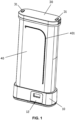
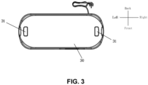
- FIG. 1 and FIG. 3 are schematic diagrams of the clothing care machine in a use state
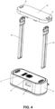
- FIG. 2 is a schematic diagram of the clothing care machine in a storage state, wherein the support column 20 is in a retracted state.
- it can also be a fixed structure without retracting.
- the retractable structure of the support column 20 may be as follows: the support column 20 includes an upper sleeve 21 and a lower sleeve 22 that are telescopically sleeved, the lower end of the lower sleeve 22 may be connected to the machine base 10, and the upper end of the upper sleeve 21 may be connected to the top seat 30.
- a fixing assembly for fixing the relative positions of the upper sleeve 21 and the lower sleeve 22 may be provided between the upper sleeve 21 and the lower sleeve 22. During use, the upper sleeve 21 and the lower sleeve 22 may be fixed by the fixing assembly to obtain stable support.
- retractable structure of the support column 20 can be retracted by releasing the fixing of the fixing assembly.
- the use of the sleeve structure of the sleeve can reduce the weight very well.
- the retractable structure of the support column 20 is not limited to this.
- the fixing assembly may include a pin fixing unit 23 and a tension adjusting unit, wherein the pin fixing unit 23 may be fixed on one side, and the tension adjusting unit may be fixed on the other side.
- the pin fixing unit 23 may include: a fixing block 234, an elastic pin 231 and a connecting rod 232.
- the fixing block 234 may be fixed in the lower opening of the upper sleeve 21, and the elastic pin 231 may be provided on the fixing block 234.
- the lower sleeve 22 may be provided with a pin hole 221 corresponding to the elastic pin 231, and under the action of no external force, the pin 2313 of the elastic pin 231 protrudes and is inserted into the corresponding pin hole 221 to make the relative positions of the upper sleeve 21 and the lower sleeve 22 fixed, such that the support column 20 can be fixedly supported.
- the connecting rod 232 may be provided in the upper sleeve 21, and the lower end of the connecting rod 232 forms an oblique guide fit with the elastic pin 231.
- the upper end of the connecting rod 232 extends to the top seat 30.
- the connecting rod 232 can be driven to be pressed down to drive the elastic pin 231 to retract. That is, when it is necessary to release the fixation of the pin fixing unit 23, the connecting rod 232 is pressed down, and the downward movement of the connecting rod 232 drives the elastic pin 231 to retract through the inclined guide fit structure, such that the pin 2313 of the elastic pin 231 is separated from the pin hole 221, such that the fixing of the pin fixing unit 23 is released.
- the lower end of the connecting rod 232 may be connected with a fitting piece 233 and forms an oblique guide fit with the elastic pin 231 through the fitting piece 233, which is convenient for connecting and fitting.
- the fitting piece 233 may be provided with a guide hole (not shown), and the fixing block 234 may be provided with a guide post 2341.
- the guide post 2341 penetrates into the guide hole to realize the guide fit, such that the fit is more precise and smoother, not easy to shift or clamp.
- the elastic pin 231 may include a spring 2312 and a pin body 2311, and a blind hole 2342 may be formed on the fixing block 234.
- the spring 2312 and the pin body 2311 may be inserted into the blind hole 2342, and the spring 2312 applies an outward elastic force to the pin body 2311.
- the outer end of the pin body 2311 protrudes with the pin 2313 mated with the pin hole 221.
- the structure is simple and easy to implement. More specifically, the fitting piece 233 forms an oblique guide fit with the pin body 2311.
- the top seat 30 may be provided with a button 31, and the upper end of the connecting rod 232 abuts the button 31.
- the connecting rod 232 is driven to be pressed down, which is convenient for operation.
- the button 31 may be a rocker button, one end of the button 31 is provided with a hinge.
- the upper end of the connecting rod 232 may be in contact with the middle position of the button 31, and the other end of the button 31 may be lifted up as a pressing end.
- the elastic adjusting unit may include a movable abutting block 26 and a cam 25.
- a receiving opening 222 may be formed on the lower sleeve 22, and the movable abutting block 26 may be provided in the receiving opening 222.
- the cam 25 may be hinged and located outside the movable abutting block 26, such that the movable abutting block 26 is located between the cam 25 and the upper sleeve 21.
- the cam 25 When it needs to be pressed, the cam 25 is rotated to make the convex portion of the cam 25 abut the movable abutting block 26, and then the movable abutting block 26 is driven to abut the upper sleeve 21, thereby compressing the upper sleeve 21 to have a further fixed effect.
- the cam 25 When it is necessary to release the pressing and tightening (i.e., when loosening), the cam 25 is rotated such that the convex portion of the cam 25 is separated from the movable abutting block 26. The operation is easy.
- the lower sleeve 22 may be also sleeved with a fixing sleeve 24 on the outer periphery, and the cam 25 may be hinged on the fixing sleeve 24, such that the cam 25 can be assembled.
- the process of fixing between the upper sleeve 21 and the lower sleeve 22 may be as follows.
- the operator holds the top seat 30 and lifts the top seat 30 up.
- the upper sleeve 21 and the lower sleeve 22 are stretched.
- the pin 2313 of the elastic pin 231 corresponds to the pin hole 221 of the lower sleeve 22 and pops out, such that the pin 2313 fits in the pin hole 221 for a fixing.
- the operator rotates the cam 25 again, such that the convex portion of the cam 25 abuts the movable abutting block 26, and then drives the movable abutting block 26 to abut the upper sleeve 21, thereby pressing the upper sleeve 21.
- the cam 25 is firstly rotated, such that the convex portion of the cam 25 is separated from the movable abutting block 26, and the fixing of the elastic adjusting unit is released.
- the button 31 on the top seat 30 is pressed down to drive the connecting rod 232 to press down, thereby releasing the fixing of the pin fixing unit 23, such that the retractable storage can be performed.
- the structure is simple and easy to operate.
- the structure of the fixing assembly is not limited to this and may be fixed by the structure of the pin fixing unit 23 alone, adopted by the other fixing components that can be fixed, etc.
- the number of the support columns 20 may be two, and the two support columns 20 may be located on the left and right sides, which play a role of uniform support and have better support stability.
- the number of the support columns 20 is not limited to this.
- the cloth cover 40 may be provided with a zipper 401, and the cloth cover 40 which may be opened and closed through the zipper 401 for taking and placing clothes into the enclosed cavity.
- the bottom of the top seat 30 may be provided with a support frame 34 provided with two support rods 341 that are oppositely provided.
- Each of the support rods 341 may be provided with slidable clamping pieces 342.
- the clamping pieces 342 of the two support rods 341 respectively clamp the two sides of the trousers, so as to realize the smooth unfolding of the clothes.
- the position adjustment of the clothes can be realized by the sliding of the clamping piece 342.
- the two side surfaces of the support rod 341 may be concave surfaces.
- the clamping piece 342 may include a clamping body 3421 and a hanging lug 3422 extending from the clamping body 3421.
- the hanging lug 3422 and the clamping body 3421 are enclosed to form a through hole 3423, and the support rod 341 may be inserted into the through hole 3423 to realize the connection between the support rod 341 and the clamping piece 342.
- One side wall of the hanging lug 3422 may be recessed inward to mate with the concave surface of one side of the support rod 341. In this way, the mating is more stable and not easy to shake.
- both ends of the support rod 341 may be respectively connected with end covers 343 and may be detachably assembled on the top seat 30 through the end covers 343.
- the support rod 341 may be detachably connected with at least one of the end covers 343. In this way, when it is necessary to increase or decrease the clamping piece 342, one of the end covers 343 may be removed, and then the clamping piece 342 is inserted into or removed from the clamping piece 342, such that the operation is easy.
- the structure of the support frame 34 is not limited to this.
- the machine base 10 may be provided with a water tank 12, a heating and vaporizing boiler 13, a condensed water collector 14 and a switch valve 16.
- the water outlet of the water tank 12 may be in communication with the water inlet of the heating and vaporizing boiler 13 to inject water into the heating and vaporizing boiler 13, and the outlet of the heating and vaporizing boiler 13 may be communicated to the steam opening 11.
- the heating and vaporizing boiler 13 heats the water inside to generate steam, and the steam is sprayed from the steam opening 11 for clothing care.
- a water pump 17 may be provided between the water tank 12 and the heating and vaporizing boiler 13, and the water in the water tank 12 may be pumped to the heating and vaporizing boiler 13 through the water pump 17, such that it is convenient for controlling the water volume and does not limit the positional relationship of the water tank 12 and the heating and vaporizing boiler 13.
- the condensed water collector 14 may be formed on the machine base 10 for collecting condensed water.
- the water outlet of the condensed water collector 14 may be connected to the water inlet 122 of the water tank 12 through a recovery channel 15.
- the switch valve 16 may be provided in the recovery channel 15, the water tank 12 may be detachably disposed on the machine base 10, and the switch valve 16 may be triggered to open when the water tank 12 is assembled. In this way, the recovery and utilization of the condensed water can be realized.
- the switch valve 16 loses the trigger of the water tank 12 and is closed to prevent the leakage of the recovered water.
- a water tank receiving cavity 101 may be recessed on the outer side of the machine base 10, and the trigger end 161 of the switch valve 16 extends into the water tank receiving cavity 101 through the top of the water tank receiving cavity 101.
- the trigger end 161 of the switch valve 16 is touched to trigger the switch valve 16 to open.
- the upper end of the water tank 12 has an inclined abutting surface 121.
- the inclined abutting surface 121 abuts the trigger end 161 of the switch valve 16 and proceeds to trigger the switch valve 16.
- the inclined abutting surface 121 has a guiding function and is not easily stuck during the contact process with the trigger end 161 of the switch valve 16, such that the action is smoother.
- the trigger end 161 of the switch valve 16 has an arc-shaped end surface for contacting the inclined abutting surface 121, which further reduces the contact resistance.
- the arrangement is not limited to this in other embodiments.
- the water outlet of the water tank 12 may be a normally closed water outlet, and the bottom of the water tank receiving cavity 101 may be provided with a butt joint 18.
- the butt joint 18 may be mated with the water outlet of the water tank 12 to open the water outlet of the water tank 12, so as to realize the water flow.
- a clothing care machine provided in the present embodiment has a substantially same structure as Embodiment 1 or Embodiment 2 or Embodiment 3 or Embodiment 4. The difference is that in the present embodiment, the upper part is directly a clothes hanger structure without a cloth cover structure. At the same time, the machine base is only provided with a steam opening in the form of a steam outlet.
- the structure of a clothing care machine provided in the present embodiment is substantially the same as that of the Embodiment 1, except that in the present embodiment, the machine base is only provided with a hot air opening in the form of a hot air outlet.
Landscapes
- Engineering & Computer Science (AREA)
- Textile Engineering (AREA)
- Professional, Industrial, Or Sporting Protective Garments (AREA)
- Accessory Of Washing/Drying Machine, Commercial Washing/Drying Machine, Other Washing/Drying Machine (AREA)
Claims (12)
- Kleidungspflegemaschine, die eine Maschinenbasis (10), eine Tragsäule (20), eine Stoffabdeckung (40) und einen oberen Teil aufweist, wobei ein Boden der Tragsäule (20) mit der Maschinenbasis (10) verbunden ist, der obere Teil mit einer Oberseite der Tragsäule (20) verbunden ist, die Stoffabdeckung (40) zwischen der Maschinenbasis (10) und einem oberen Sitz (30) zur Bildung eines eingeschlossenen Hohlraums vorgesehen ist und die Maschinenbasis (10) mit mindestens einer einer Dampföffnung (11) und einer Heißluftöffnung (19) versehen ist,wobei die Tragsäule (20) eine obere Hülse (21) und eine untere Hülse (22) aufweist, die teleskopisch ummantelt sind, ein unteres Ende der unteren Hülse (22) mit der Maschinenbasis (10) verbunden ist, ein oberes Ende der oberen Hülse (21) mit dem oberen Teil verbunden ist und eine Fixieranordnung zum Fixieren von relativen Positionen der oberen Hülse (21) und der unteren Hülse (22) zwischen der oberen Hülse (21) und der unteren Hülse (22) vorgesehen ist, und dadurch gekennzeichnet,dass die Fixieranordnung eine Stiftfixiereinheit (23) aufweist und die Stiftfixiereinheit (23) einen Fixierblock (234), einen elastischen Stift (231) und eine Verbindungsstange (232) aufweist, der Fixierblock (234) in einer unteren Öffnung der oberen Hülse (21) fixiert ist, der elastische Stift (231) auf dem Fixierblock (234) vorgesehen ist, die untere Hülse (22) mit einem Stiftloch (221) versehen ist, das dem elastischen Stift (231) entspricht, ein Stift (2313) des elastischen Stifts (231) unter Einwirkung keiner externen Kraft herausragt und in das entsprechende Stiftloch (221) eingesetzt ist, so dass die relativen Positionen der oberen Hülse (21) und der unteren Hülse (22) fixiert sind, die Verbindungsstange (232) in der oberen Hülse (21) vorgesehen ist, ein unteres Ende der Verbindungsstange (232) eine schräge Führungspassung mit dem elastischen Stift (231) bildet, ein oberes Ende der Verbindungsstange (232) sich zum oberen Sitz (30) erstreckt und der elastische Stift (231) angetrieben ist, um sich durch das obere Ende der Verbindungsstange (232) zurückzuziehen, indem die Verbindungsstange (232) nach unten gedrückt wird.
- Kleidungspflegemaschine gemäß Anspruch 1, wobei das untere Ende der Verbindungsstange (232) mit einem mit einem Führungsloch versehenen Passstück (233) verbunden ist, der Fixierblock (234) mit einem in das Führungsloch eindringenden Führungsstift (2341) versehen ist und der Fixierblock (234) mit dem elastischen Stift (231) durch das Passstück (233) hindurch einen schrägen Führungssitz bildet.
- Kleidungspflegemaschine gemäß Anspruch 2, wobei der elastische Stift (231) eine Feder (2312) und einen Stiftkörper (2311) aufweist, der Fixierblock (234) mit einem Sackloch (2342) versehen ist, die Feder (2312) und der Stiftkörper (2311) in das Sackloch (2342) eingesetzt sind und, wenn die Feder (2312) eine nach außen gerichtete elastische Kraft auf den Stiftkörper (2311) ausübt, ein äußeres Ende des Stiftkörpers (2311) mit dem Stift (2313), der mit dem Stiftloch (221) zusammenpasst, hervorsteht.
- Kleidungspflegemaschine gemäß Anspruch 1, wobei der obere Teil mit einem Knopf (31) versehen ist, das obere Ende der Verbindungsstange (232) am Knopf (31) anliegt und die Verbindungsstange (232) durch Drücken des Knopfes (31) nach unten gedrückt ist.
- Kleidungspflegemaschine gemäß Anspruch 1, wobei die Fixieranordnung des Weiteren eine elastische Einstelleinheit aufweist, die einen beweglichen Anlageblock (26) und einen Nocken (25) aufweist, die untere Hülse (22) mit einer Aufnahmeöffnung (222) versehen ist, der bewegliche Anlageblock (26) in der Aufnahmeöffnung (222) vorgesehen ist und der Nocken (25) mit einem Scharnier versehen und außerhalb des beweglichen Anlageblocks (26) angeordnet ist, so dass der bewegliche Anlageblock (26) zwischen dem Nocken (25) und der oberen Hülse (21) angeordnet ist.
- Kleidungspflegemaschine gemäß Anspruch 1, wobei der obere Teil mit einem Stützrahmen (34) versehen ist, der mit einer Stützstange (341) versehen ist, und die Stützstange (341) mit einem Klemmstück (342) versehen ist.
- Kleidungspflegemaschine gemäß Anspruch 6, wobei zwei Seitenflächen der Stützstange (341) konkave Flächen sind, das Klemmstück (342) einen Klemmkörper (3421) und eine sich vom Klemmkörper (3421) erstreckende Aufhängeöse (3422) aufweist, die Aufhängeöse (3422) und der Klemmkörper (3421) zur Bildung eines Durchgangslochs (3423) eingeschlossen sind, die Stützstange (341) in das Durchgangsloch (3423) eindringt, um eine Verbindung zwischen der Stützstange (341) und dem Klemmstück (342) herzustellen, und eine Seitenwand der Aufhängeöse (3422) nach innen vertieft ist und mit einer konkaven Seitenfläche der Stützstange (341) zusammenpasst.
- Kleidungspflegemaschine gemäß Anspruch 7, wobei zwei Enden der Stützstange (341) jeweils mit Endabdeckungen (343) verbunden sind und durch die Endabdeckungen (343) abnehmbar auf dem oberen Sitz (30) angebracht sind und die Stützstange (341) abnehmbar mit mindestens einer der Endabdeckungen (343) verbunden ist.
- Kleidungspflegemaschine gemäß Anspruch 1, wobei die Maschinenbasis (10) mit einem Wassertank (12), einem Heiz- und Verdampfungskessel (13), einem Kondenswassersammler (14) und einem Schaltventil (16) versehen ist, ein Wasserauslass des Wassertanks (12) mit einem Wassereinlass (122) des Heiz- und Verdampfungskessels (13) verbunden ist, ein Auslass des Heiz- und Verdampfungskessels (13) mit der Dampföffnung (11) verbunden ist, der Kondenswassersammler (14) auf der Maschinenbasis (10) zum Sammeln von Kondenswasser angeordnet ist, ein Wasserauslass des Kondenswassersammlers (14) über einen Rückgewinnungskanal (15) mit einem Wassereinlass (122) des Wassertanks (12) in Verbindung steht, das Schaltventil (16) im Rückgewinnungskanal (15) vorgesehen ist, der Wassertank (12) abnehmbar auf der Maschinenbasis (10) vorgesehen ist und das Schaltventil (16) ausgelöst wird, um zu öffnen, wenn der Wassertank (12) montiert ist.
- Kleidungspflegemaschine gemäß Anspruch 9, wobei ein oberes Ende des Wassertanks (12) eine geneigte Anlagefläche (121) aufweist, eine Außenseite der Maschinenbasis (10) mit einem Wassertankaufnahmehohlraum (101) vertieft ist, ein Auslöseende (161) des Schaltventils (16) sich in den Wassertankaufnahmehohlraum (101) durch eine Oberseite des Wassertankaufnahmehohlraums (101) erstreckt und, wenn der Wassertank (12) in den Wassertankaufnahmehohlraum (101) eingebaut ist, die geneigte Anlagefläche (121) am Auslöseende (161) des Schaltventils (16) anliegt und das Schaltventil (16) ausgelöst wird, um aktiviert zu werden.
- Kleidungspflegemaschine gemäß Anspruch 9, wobei der Wasserauslass des Wassertanks (12) ein normalerweise geschlossener Wasserauslass ist, der Wassertankaufnahmehohlraum (101) mit einer Stoßverbindung (18) an einem Boden des Wassertankaufnahmehohlraums (101) versehen ist und, wenn der Wassertank (12) in den Wassertankaufnahmehohlraum (101) eingebaut ist, die Stoßverbindung (18) mit dem Wasserauslass des Wassertanks (12) zusammenwirkt, um den Wasserauslass des Wassertanks (12) zu öffnen.
- Kleidungspflegemaschine gemäß Anspruch 9, wobei eine Wasserpumpe (17) zwischen dem Wassertank (12) und dem Heiz- und Verdampfungskessel (13) vorgesehen ist und Wasser im Wassertank (12) durch die Wasserpumpe (17) in den Heiz- und Verdampfungskessel (13) gepumpt wird.
Applications Claiming Priority (1)
| Application Number | Priority Date | Filing Date | Title |
|---|---|---|---|
| CN202110932429.4A CN115704180B (zh) | 2021-08-13 | 2021-08-13 | 一种衣物护理机 |
Publications (2)
| Publication Number | Publication Date |
|---|---|
| EP4134483A1 EP4134483A1 (de) | 2023-02-15 |
| EP4134483B1 true EP4134483B1 (de) | 2025-05-21 |
Family
ID=82156587
Family Applications (1)
| Application Number | Title | Priority Date | Filing Date |
|---|---|---|---|
| EP22180010.5A Active EP4134483B1 (de) | 2021-08-13 | 2022-06-20 | Kleidungspflegemaschine |
Country Status (3)
| Country | Link |
|---|---|
| US (1) | US12522976B2 (de) |
| EP (1) | EP4134483B1 (de) |
| CN (1) | CN115704180B (de) |
Families Citing this family (4)
| Publication number | Priority date | Publication date | Assignee | Title |
|---|---|---|---|---|
| USD1036036S1 (en) * | 2021-10-19 | 2024-07-16 | Lg Electronics Inc. | Clothing care machine for vehicles |
| US20250066985A1 (en) * | 2023-08-25 | 2025-02-27 | Samsung Electronics Co., Ltd. | Clothes care apparatus |
| USD1118058S1 (en) * | 2024-10-17 | 2026-03-10 | Nvision Electrical Appliance Co., Ltd. | Handheld garment steamer |
| USD1119129S1 (en) * | 2024-10-17 | 2026-03-17 | Nvision Electrical Appliance Co., Ltd. | Handheld garment steamer |
Family Cites Families (28)
| Publication number | Priority date | Publication date | Assignee | Title |
|---|---|---|---|---|
| US3409996A (en) * | 1965-04-05 | 1968-11-12 | Konstandt Francisco Goldberger | Heating, drying and ventilating apparatus |
| HU200088B (en) * | 1988-03-25 | 1990-04-28 | Rubik Erno | Gripping device particularly pincers |
| US5528912A (en) * | 1995-08-18 | 1996-06-25 | Weber; Barry J. | Automatic and travel steamer |
| JP3397204B2 (ja) * | 2001-04-25 | 2003-04-14 | 松下電器産業株式会社 | 洗濯装置 |
| US6581737B2 (en) * | 2001-09-06 | 2003-06-24 | Chien-Shan Wang | Anchoring apparatus for multi-section pulling bar of trunks |
| US20030126691A1 (en) * | 2001-12-20 | 2003-07-10 | Gerlach Christian Gerhard Friedrich | Fabric article treating method and apparatus |
| US20080256989A1 (en) * | 2005-02-08 | 2008-10-23 | Lg Electronics Inc. | Refresher and Machine for Washing or Drying with the Same |
| US7266863B2 (en) * | 2005-03-22 | 2007-09-11 | Theprem Success Co., Ltd | Retractable handle assembly for luggage |
| CN100554566C (zh) * | 2006-08-04 | 2009-10-28 | 胡杰波 | 一种柜式干衣机 |
| US20080078053A1 (en) * | 2006-10-02 | 2008-04-03 | Theprem Success Co., Ltd. | Retractable pull handle for luggage |
| US20080222909A1 (en) * | 2007-03-12 | 2008-09-18 | Augusto Picozza | Drying apparatus |
| JP5086724B2 (ja) * | 2007-06-14 | 2012-11-28 | 富士機工株式会社 | ステアリングコラム装置 |
| EP3460120B1 (de) * | 2009-05-11 | 2023-07-12 | Electrolux Home Products Corporation N.V. | Waschmaschine |
| CN104520491B (zh) * | 2012-02-16 | 2016-12-21 | Lg电子株式会社 | 衣物处理设备 |
| WO2014030087A1 (en) * | 2012-08-21 | 2014-02-27 | Koninklijke Philips N.V. | Enclosure for a steamer |
| US8746267B2 (en) * | 2012-10-01 | 2014-06-10 | Bravo Sports | Height-adjustable canopy leg |
| US20140137370A1 (en) * | 2012-11-16 | 2014-05-22 | Cx Technology Corporation | Positioning mechanism for travel bag retractable handle |
| US20140158851A1 (en) * | 2012-12-06 | 2014-06-12 | Monkey Armz, Llc | Clamp |
| US20140241789A1 (en) * | 2013-02-28 | 2014-08-28 | E Dan Industrial Co., Ltd | Locking device for an extendible tube assembly |
| KR102369584B1 (ko) * | 2014-12-19 | 2022-03-03 | 엘지전자 주식회사 | 의류처리장치 |
| KR102493966B1 (ko) * | 2016-02-16 | 2023-02-01 | 주식회사 위니아전자 | 세탁기 |
| WO2018064620A1 (en) * | 2016-09-29 | 2018-04-05 | Mqhg, Llc | Object-securable article-carrier apparatus and kit |
| TWI623282B (zh) * | 2017-05-31 | 2018-05-11 | 賴偉浤 | 旅行箱手把結構 |
| KR20190038980A (ko) * | 2017-10-02 | 2019-04-10 | 김영찬 | 다기능 빨래건조장치 |
| KR102132154B1 (ko) * | 2018-11-14 | 2020-07-09 | (주)동양이지텍 | 방수천 커버의 교환과 세탁이 용이한 의류 관리기 |
| US11384477B2 (en) * | 2020-08-14 | 2022-07-12 | Conair Llc | Garment steamer system with multi-function air and steam chamber |
| CN215628862U (zh) * | 2021-03-19 | 2022-01-25 | 广州视源电子科技股份有限公司 | 衣物护理机 |
| FR3123665B1 (fr) * | 2021-06-02 | 2024-08-09 | Seb Sa | Enceinte de défroissage pliable comprenant un rideau avec une paroi textile et une armature |
-
2021
- 2021-08-13 CN CN202110932429.4A patent/CN115704180B/zh active Active
-
2022
- 2022-06-15 US US17/840,976 patent/US12522976B2/en active Active
- 2022-06-20 EP EP22180010.5A patent/EP4134483B1/de active Active
Also Published As
| Publication number | Publication date |
|---|---|
| CN115704180A (zh) | 2023-02-17 |
| CN115704180B (zh) | 2026-03-20 |
| EP4134483A1 (de) | 2023-02-15 |
| US20230046720A1 (en) | 2023-02-16 |
| US12522976B2 (en) | 2026-01-13 |
Similar Documents
| Publication | Publication Date | Title |
|---|---|---|
| EP4134483A1 (de) | Kleidungspflegemaschine | |
| CN219556895U (zh) | 一种适用于窄领的快速衣架 | |
| CN110344228A (zh) | 一种具有锁定装置的熨烫设备 | |
| CN217298383U (zh) | 蒸汽熨烫装置 | |
| US20060191299A1 (en) | Garment steamer | |
| CN110382769A (zh) | 系统熨斗 | |
| CN116268915A (zh) | 一种适用于窄领的快速衣架 | |
| CN106222952A (zh) | 洗衣机的底座、洗衣机和用于洗衣机的挂烫装置 | |
| CN205617100U (zh) | 波轮洗衣机 | |
| CN106480689B (zh) | 熨烫装置及设备 | |
| KR100668772B1 (ko) | 집게, 행거 및 이를 채택한 스팀 다리미 | |
| CN214882467U (zh) | 一种具有可熨烫装置的衣物护理柜 | |
| CN114672975B (zh) | 一种多功能衣架 | |
| CN112281434B (zh) | 一种具有多角度定位熨烫板的挂烫机 | |
| CN206538605U (zh) | 翻转烫板挂烫机 | |
| CN222064973U (zh) | 可夹衣整形的手持熨烫装置 | |
| CN110382770A (zh) | 系统熨斗 | |
| CN222313602U (zh) | 一种手持挂烫机的旋转把手结构及其挂烫机 | |
| CN201620290U (zh) | 折叠式挂烫机用衣架 | |
| CN110366620A (zh) | 系统熨斗 | |
| CN223316957U (zh) | 干衣机 | |
| KR200275643Y1 (ko) | 케이스가 구비되는 우산 | |
| KR200499727Y1 (ko) | 접이식 옷걸이 | |
| CN219752780U (zh) | 一种熨衣板转动结构 | |
| CN223343017U (zh) | 一种晾晒装置及晾衣机 |
Legal Events
| Date | Code | Title | Description |
|---|---|---|---|
| PUAI | Public reference made under article 153(3) epc to a published international application that has entered the european phase |
Free format text: ORIGINAL CODE: 0009012 |
|
| STAA | Information on the status of an ep patent application or granted ep patent |
Free format text: STATUS: THE APPLICATION HAS BEEN PUBLISHED |
|
| AK | Designated contracting states |
Kind code of ref document: A1 Designated state(s): AL AT BE BG CH CY CZ DE DK EE ES FI FR GB GR HR HU IE IS IT LI LT LU LV MC MK MT NL NO PL PT RO RS SE SI SK SM TR |
|
| STAA | Information on the status of an ep patent application or granted ep patent |
Free format text: STATUS: REQUEST FOR EXAMINATION WAS MADE |
|
| 17P | Request for examination filed |
Effective date: 20230816 |
|
| RBV | Designated contracting states (corrected) |
Designated state(s): AL AT BE BG CH CY CZ DE DK EE ES FI FR GB GR HR HU IE IS IT LI LT LU LV MC MK MT NL NO PL PT RO RS SE SI SK SM TR |
|
| GRAP | Despatch of communication of intention to grant a patent |
Free format text: ORIGINAL CODE: EPIDOSNIGR1 |
|
| STAA | Information on the status of an ep patent application or granted ep patent |
Free format text: STATUS: GRANT OF PATENT IS INTENDED |
|
| RIC1 | Information provided on ipc code assigned before grant |
Ipc: D06F 58/14 20060101ALI20241106BHEP Ipc: D06F 73/02 20060101AFI20241106BHEP |
|
| INTG | Intention to grant announced |
Effective date: 20241211 |
|
| GRAS | Grant fee paid |
Free format text: ORIGINAL CODE: EPIDOSNIGR3 |
|
| GRAA | (expected) grant |
Free format text: ORIGINAL CODE: 0009210 |
|
| STAA | Information on the status of an ep patent application or granted ep patent |
Free format text: STATUS: THE PATENT HAS BEEN GRANTED |
|
| AK | Designated contracting states |
Kind code of ref document: B1 Designated state(s): AL AT BE BG CH CY CZ DE DK EE ES FI FR GB GR HR HU IE IS IT LI LT LU LV MC MK MT NL NO PL PT RO RS SE SI SK SM TR |
|
| REG | Reference to a national code |
Ref country code: GB Ref legal event code: FG4D |
|
| REG | Reference to a national code |
Ref country code: CH Ref legal event code: EP |
|
| REG | Reference to a national code |
Ref country code: DE Ref legal event code: R096 Ref document number: 602022014851 Country of ref document: DE |
|
| REG | Reference to a national code |
Ref country code: IE Ref legal event code: FG4D |
|
| PGFP | Annual fee paid to national office [announced via postgrant information from national office to epo] |
Ref country code: FR Payment date: 20250630 Year of fee payment: 4 |
|
| PGFP | Annual fee paid to national office [announced via postgrant information from national office to epo] |
Ref country code: AT Payment date: 20250721 Year of fee payment: 4 |
|
| REG | Reference to a national code |
Ref country code: NL Ref legal event code: MP Effective date: 20250521 |
|
| PG25 | Lapsed in a contracting state [announced via postgrant information from national office to epo] |
Ref country code: PT Free format text: LAPSE BECAUSE OF FAILURE TO SUBMIT A TRANSLATION OF THE DESCRIPTION OR TO PAY THE FEE WITHIN THE PRESCRIBED TIME-LIMIT Effective date: 20250922 Ref country code: ES Free format text: LAPSE BECAUSE OF FAILURE TO SUBMIT A TRANSLATION OF THE DESCRIPTION OR TO PAY THE FEE WITHIN THE PRESCRIBED TIME-LIMIT Effective date: 20250521 Ref country code: FI Free format text: LAPSE BECAUSE OF FAILURE TO SUBMIT A TRANSLATION OF THE DESCRIPTION OR TO PAY THE FEE WITHIN THE PRESCRIBED TIME-LIMIT Effective date: 20250521 |
|
| REG | Reference to a national code |
Ref country code: LT Ref legal event code: MG9D |
|
| PG25 | Lapsed in a contracting state [announced via postgrant information from national office to epo] |
Ref country code: NO Free format text: LAPSE BECAUSE OF FAILURE TO SUBMIT A TRANSLATION OF THE DESCRIPTION OR TO PAY THE FEE WITHIN THE PRESCRIBED TIME-LIMIT Effective date: 20250821 Ref country code: GR Free format text: LAPSE BECAUSE OF FAILURE TO SUBMIT A TRANSLATION OF THE DESCRIPTION OR TO PAY THE FEE WITHIN THE PRESCRIBED TIME-LIMIT Effective date: 20250822 |
|
| PG25 | Lapsed in a contracting state [announced via postgrant information from national office to epo] |
Ref country code: NL Free format text: LAPSE BECAUSE OF FAILURE TO SUBMIT A TRANSLATION OF THE DESCRIPTION OR TO PAY THE FEE WITHIN THE PRESCRIBED TIME-LIMIT Effective date: 20250521 Ref country code: PL Free format text: LAPSE BECAUSE OF FAILURE TO SUBMIT A TRANSLATION OF THE DESCRIPTION OR TO PAY THE FEE WITHIN THE PRESCRIBED TIME-LIMIT Effective date: 20250521 |
|
| PG25 | Lapsed in a contracting state [announced via postgrant information from national office to epo] |
Ref country code: BG Free format text: LAPSE BECAUSE OF FAILURE TO SUBMIT A TRANSLATION OF THE DESCRIPTION OR TO PAY THE FEE WITHIN THE PRESCRIBED TIME-LIMIT Effective date: 20250521 |
|
| PG25 | Lapsed in a contracting state [announced via postgrant information from national office to epo] |
Ref country code: HR Free format text: LAPSE BECAUSE OF FAILURE TO SUBMIT A TRANSLATION OF THE DESCRIPTION OR TO PAY THE FEE WITHIN THE PRESCRIBED TIME-LIMIT Effective date: 20250521 |
|
| PG25 | Lapsed in a contracting state [announced via postgrant information from national office to epo] |
Ref country code: RS Free format text: LAPSE BECAUSE OF FAILURE TO SUBMIT A TRANSLATION OF THE DESCRIPTION OR TO PAY THE FEE WITHIN THE PRESCRIBED TIME-LIMIT Effective date: 20250821 |
|
| PG25 | Lapsed in a contracting state [announced via postgrant information from national office to epo] |
Ref country code: IS Free format text: LAPSE BECAUSE OF FAILURE TO SUBMIT A TRANSLATION OF THE DESCRIPTION OR TO PAY THE FEE WITHIN THE PRESCRIBED TIME-LIMIT Effective date: 20250921 |
|
| PG25 | Lapsed in a contracting state [announced via postgrant information from national office to epo] |
Ref country code: LV Free format text: LAPSE BECAUSE OF FAILURE TO SUBMIT A TRANSLATION OF THE DESCRIPTION OR TO PAY THE FEE WITHIN THE PRESCRIBED TIME-LIMIT Effective date: 20250521 |
|
| REG | Reference to a national code |
Ref country code: AT Ref legal event code: MK05 Ref document number: 1796835 Country of ref document: AT Kind code of ref document: T Effective date: 20250521 |
|
| PG25 | Lapsed in a contracting state [announced via postgrant information from national office to epo] |
Ref country code: AT Free format text: LAPSE BECAUSE OF FAILURE TO SUBMIT A TRANSLATION OF THE DESCRIPTION OR TO PAY THE FEE WITHIN THE PRESCRIBED TIME-LIMIT Effective date: 20250521 Ref country code: DK Free format text: LAPSE BECAUSE OF FAILURE TO SUBMIT A TRANSLATION OF THE DESCRIPTION OR TO PAY THE FEE WITHIN THE PRESCRIBED TIME-LIMIT Effective date: 20250521 Ref country code: SM Free format text: LAPSE BECAUSE OF FAILURE TO SUBMIT A TRANSLATION OF THE DESCRIPTION OR TO PAY THE FEE WITHIN THE PRESCRIBED TIME-LIMIT Effective date: 20250521 |
|
| PG25 | Lapsed in a contracting state [announced via postgrant information from national office to epo] |
Ref country code: CZ Free format text: LAPSE BECAUSE OF FAILURE TO SUBMIT A TRANSLATION OF THE DESCRIPTION OR TO PAY THE FEE WITHIN THE PRESCRIBED TIME-LIMIT Effective date: 20250521 |
|
| PG25 | Lapsed in a contracting state [announced via postgrant information from national office to epo] |
Ref country code: EE Free format text: LAPSE BECAUSE OF FAILURE TO SUBMIT A TRANSLATION OF THE DESCRIPTION OR TO PAY THE FEE WITHIN THE PRESCRIBED TIME-LIMIT Effective date: 20250521 |
|
| PG25 | Lapsed in a contracting state [announced via postgrant information from national office to epo] |
Ref country code: SK Free format text: LAPSE BECAUSE OF FAILURE TO SUBMIT A TRANSLATION OF THE DESCRIPTION OR TO PAY THE FEE WITHIN THE PRESCRIBED TIME-LIMIT Effective date: 20250521 |
|
| REG | Reference to a national code |
Ref country code: CH Ref legal event code: H13 Free format text: ST27 STATUS EVENT CODE: U-0-0-H10-H13 (AS PROVIDED BY THE NATIONAL OFFICE) Effective date: 20260127 Ref country code: DE Ref legal event code: R082 Ref document number: 602022014851 Country of ref document: DE |
|
| PG25 | Lapsed in a contracting state [announced via postgrant information from national office to epo] |
Ref country code: IT Free format text: LAPSE BECAUSE OF FAILURE TO SUBMIT A TRANSLATION OF THE DESCRIPTION OR TO PAY THE FEE WITHIN THE PRESCRIBED TIME-LIMIT Effective date: 20250521 |
|
| PG25 | Lapsed in a contracting state [announced via postgrant information from national office to epo] |
Ref country code: RO Free format text: LAPSE BECAUSE OF FAILURE TO SUBMIT A TRANSLATION OF THE DESCRIPTION OR TO PAY THE FEE WITHIN THE PRESCRIBED TIME-LIMIT Effective date: 20250521 |
|
| PG25 | Lapsed in a contracting state [announced via postgrant information from national office to epo] |
Ref country code: LU Free format text: LAPSE BECAUSE OF NON-PAYMENT OF DUE FEES Effective date: 20250620 |
|
| PG25 | Lapsed in a contracting state [announced via postgrant information from national office to epo] |
Ref country code: MC Free format text: LAPSE BECAUSE OF FAILURE TO SUBMIT A TRANSLATION OF THE DESCRIPTION OR TO PAY THE FEE WITHIN THE PRESCRIBED TIME-LIMIT Effective date: 20250521 |
|
| REG | Reference to a national code |
Ref country code: DE Ref legal event code: R097 Ref document number: 602022014851 Country of ref document: DE |
|
| REG | Reference to a national code |
Ref country code: BE Ref legal event code: MM Effective date: 20250630 |
|
| PLBE | No opposition filed within time limit |
Free format text: ORIGINAL CODE: 0009261 |
|
| STAA | Information on the status of an ep patent application or granted ep patent |
Free format text: STATUS: NO OPPOSITION FILED WITHIN TIME LIMIT |
|
| REG | Reference to a national code |
Ref country code: CH Ref legal event code: L10 Free format text: ST27 STATUS EVENT CODE: U-0-0-L10-L00 (AS PROVIDED BY THE NATIONAL OFFICE) Effective date: 20260402 |
|
| PG25 | Lapsed in a contracting state [announced via postgrant information from national office to epo] |
Ref country code: IE Free format text: LAPSE BECAUSE OF NON-PAYMENT OF DUE FEES Effective date: 20250620 |
|
| PG25 | Lapsed in a contracting state [announced via postgrant information from national office to epo] |
Ref country code: BE Free format text: LAPSE BECAUSE OF NON-PAYMENT OF DUE FEES Effective date: 20250630 |
|
| PG25 | Lapsed in a contracting state [announced via postgrant information from national office to epo] |
Ref country code: CH Free format text: LAPSE BECAUSE OF NON-PAYMENT OF DUE FEES Effective date: 20250630 |
|
| 26N | No opposition filed |
Effective date: 20260224 |
|
| PG25 | Lapsed in a contracting state [announced via postgrant information from national office to epo] |
Ref country code: LT Free format text: LAPSE BECAUSE OF FAILURE TO SUBMIT A TRANSLATION OF THE DESCRIPTION OR TO PAY THE FEE WITHIN THE PRESCRIBED TIME-LIMIT Effective date: 20250521 |
|
| PGFP | Annual fee paid to national office [announced via postgrant information from national office to epo] |
Ref country code: DE Payment date: 20260622 Year of fee payment: 5 |
|
| PG25 | Lapsed in a contracting state [announced via postgrant information from national office to epo] |
Ref country code: SE Free format text: LAPSE BECAUSE OF FAILURE TO SUBMIT A TRANSLATION OF THE DESCRIPTION OR TO PAY THE FEE WITHIN THE PRESCRIBED TIME-LIMIT Effective date: 20250521 Ref country code: CY Free format text: LAPSE BECAUSE OF FAILURE TO SUBMIT A TRANSLATION OF THE DESCRIPTION OR TO PAY THE FEE WITHIN THE PRESCRIBED TIME-LIMIT Effective date: 20250521 |