EP4134183A1 - Procédé pour l'identification d'allongement limite de constriction de plaque métallique - Google Patents
Procédé pour l'identification d'allongement limite de constriction de plaque métallique Download PDFInfo
- Publication number
- EP4134183A1 EP4134183A1 EP20930236.3A EP20930236A EP4134183A1 EP 4134183 A1 EP4134183 A1 EP 4134183A1 EP 20930236 A EP20930236 A EP 20930236A EP 4134183 A1 EP4134183 A1 EP 4134183A1
- Authority
- EP
- European Patent Office
- Prior art keywords
- strain
- necking
- tensile
- sheet
- gradient
- Prior art date
- Legal status (The legal status is an assumption and is not a legal conclusion. Google has not performed a legal analysis and makes no representation as to the accuracy of the status listed.)
- Pending
Links
Images


Classifications
-
- B—PERFORMING OPERATIONS; TRANSPORTING
- B21—MECHANICAL METAL-WORKING WITHOUT ESSENTIALLY REMOVING MATERIAL; PUNCHING METAL
- B21D—WORKING OR PROCESSING OF SHEET METAL OR METAL TUBES, RODS OR PROFILES WITHOUT ESSENTIALLY REMOVING MATERIAL; PUNCHING METAL
- B21D22/00—Shaping without cutting, by stamping, spinning, or deep-drawing
- B21D22/20—Deep-drawing
- B21D22/30—Deep-drawing to finish articles formed by deep-drawing
-
- G—PHYSICS
- G01—MEASURING; TESTING
- G01N—INVESTIGATING OR ANALYSING MATERIALS BY DETERMINING THEIR CHEMICAL OR PHYSICAL PROPERTIES
- G01N3/00—Investigating strength properties of solid materials by application of mechanical stress
- G01N3/08—Investigating strength properties of solid materials by application of mechanical stress by applying steady tensile or compressive forces
-
- B—PERFORMING OPERATIONS; TRANSPORTING
- B21—MECHANICAL METAL-WORKING WITHOUT ESSENTIALLY REMOVING MATERIAL; PUNCHING METAL
- B21C—MANUFACTURE OF METAL SHEETS, WIRE, RODS, TUBES OR PROFILES, OTHERWISE THAN BY ROLLING; AUXILIARY OPERATIONS USED IN CONNECTION WITH METAL-WORKING WITHOUT ESSENTIALLY REMOVING MATERIAL
- B21C51/00—Measuring, gauging, indicating, counting, or marking devices specially adapted for use in the production or manipulation of material in accordance with subclasses B21B - B21F
-
- B—PERFORMING OPERATIONS; TRANSPORTING
- B21—MECHANICAL METAL-WORKING WITHOUT ESSENTIALLY REMOVING MATERIAL; PUNCHING METAL
- B21D—WORKING OR PROCESSING OF SHEET METAL OR METAL TUBES, RODS OR PROFILES WITHOUT ESSENTIALLY REMOVING MATERIAL; PUNCHING METAL
- B21D24/00—Special deep-drawing arrangements in, or in connection with, presses
- B21D24/005—Multi-stage presses
-
- B—PERFORMING OPERATIONS; TRANSPORTING
- B21—MECHANICAL METAL-WORKING WITHOUT ESSENTIALLY REMOVING MATERIAL; PUNCHING METAL
- B21D—WORKING OR PROCESSING OF SHEET METAL OR METAL TUBES, RODS OR PROFILES WITHOUT ESSENTIALLY REMOVING MATERIAL; PUNCHING METAL
- B21D53/00—Making other particular articles
- B21D53/88—Making other particular articles other parts for vehicles, e.g. cowlings, mudguards
-
- G—PHYSICS
- G01—MEASURING; TESTING
- G01N—INVESTIGATING OR ANALYSING MATERIALS BY DETERMINING THEIR CHEMICAL OR PHYSICAL PROPERTIES
- G01N2203/00—Investigating strength properties of solid materials by application of mechanical stress
- G01N2203/0014—Type of force applied
- G01N2203/0016—Tensile or compressive
- G01N2203/0017—Tensile
-
- G—PHYSICS
- G01—MEASURING; TESTING
- G01N—INVESTIGATING OR ANALYSING MATERIALS BY DETERMINING THEIR CHEMICAL OR PHYSICAL PROPERTIES
- G01N2203/00—Investigating strength properties of solid materials by application of mechanical stress
- G01N2203/0058—Kind of property studied
- G01N2203/006—Crack, flaws, fracture or rupture
- G01N2203/0062—Crack or flaws
- G01N2203/0064—Initiation of crack
-
- G—PHYSICS
- G01—MEASURING; TESTING
- G01N—INVESTIGATING OR ANALYSING MATERIALS BY DETERMINING THEIR CHEMICAL OR PHYSICAL PROPERTIES
- G01N2203/00—Investigating strength properties of solid materials by application of mechanical stress
- G01N2203/02—Details not specific for a particular testing method
- G01N2203/026—Specifications of the specimen
- G01N2203/0262—Shape of the specimen
- G01N2203/027—Specimens with holes or notches
-
- G—PHYSICS
- G01—MEASURING; TESTING
- G01N—INVESTIGATING OR ANALYSING MATERIALS BY DETERMINING THEIR CHEMICAL OR PHYSICAL PROPERTIES
- G01N2203/00—Investigating strength properties of solid materials by application of mechanical stress
- G01N2203/02—Details not specific for a particular testing method
- G01N2203/026—Specifications of the specimen
- G01N2203/0262—Shape of the specimen
- G01N2203/0278—Thin specimens
- G01N2203/0282—Two dimensional, e.g. tapes, webs, sheets, strips, disks or membranes
Definitions
- the present invention relates to a method for identifying a necking limit strain of a metal sheet, and in particular, a method for identifying a necking limit strain of a metal sheet that identifies the relation between the necking limit strain, which is the strain at the time of occurrence of necking by imparting tensile deformation to the sheet edge of the metal sheet, and the strain gradient.
- Press forming products for example, automotive parts and automotive body components
- press forming using tools of press forming.
- the stretch flanging of a blank is often accompanied.
- the sheet edges of the blank may reach a fracture limit during the press forming and may fracture, which causes a problem.
- the stretch flanging will reach the fracture limit during the press forming before the fracture occurs.
- Patent Literature 1 and Patent Literature 2 have been disclosed, for example.
- the method disclosed in Patent Literature 1 performs a hole expansion test in which stretch flanging limit strain at the sheared edge of a metal material is obtained by changing an initial hole diameter and the shape of a hole expanding puncher and the FEM analysis in which the fracture limit strain of the hole edge (stretch flanging limit strain) and the strain gradients in the radial direction of the hole edge and thickness direction are calculated .
- the method disclosed in Patent Literature 1 identifies the stretch flanging limit strain from the relation between the stretch flanging limit strain obtained from the hole expansion test and the strain gradients calculated by the FEM analysis and uses this as an index of the fracture limit.
- Patent Literature 2 performs a side bending test on sheet specimens on which an arcuate shape of a different curvature is formed at the sheet end portion, and from the relation among the fracture strain at the fracture portion, the strain gradients in the arcuate radial direction and tangential direction, and the strain concentration, and identifies the fracture strain that occurs at the flange portion when stretch flanging is performed.
- the present invention has been made in view of the above-described problems, and an object of the present invention is to provide a method for identifying a necking limit strain of a metal sheet that is capable of identifying the necking limit strain easily and accurately when the necking occurs at the sheet edge of the metal sheet in press forming accompanied with stretch flanging and capable of predicting the occurrence of fracture in advance in mass production.
- a method for identifying a necking limit strain of a metal sheet identifies a relation between a necking limit strain, at which necking occurs at a sheet edge of a metal sheet by imparting tensile deformation, and a strain gradient, and includes: a strain distribution measurement step of measuring, for two or more types of sheet specimens having a notch geometry for which a portion of a sheet edge is notched inward and having a different strain gradient in a tensile orthogonal direction that is orthogonal to a tensile direction when tensile deformation is imparted to a notch root of the notch geometry, distribution of strain of the notch root in the tensile orthogonal direction in a tensile deformation process; a strain increment ratio/strain gradient acquisition step of obtaining, for each of the sheet specimens, a strain increment ratio of the notch root in the tensile deformation process and a strain gradient in the tensile orthogonal direction, from the distribution of the strain
- the strain distribution measurement step may impart tensile deformation to the notch root by applying a tensile load in a uniaxial direction to the sheet specimen.
- the strain distribution measurement step may measure the distribution of the strain in the tensile orthogonal direction by an image correlation method.
- the present invention it is possible to identify the necking limit strain easily and accurately when necking occurred at the sheet edge of a metal sheet in press forming accompanied with stretch flanging. Moreover, according to the present invention, by the press forming simulation, it is possible to accurately predict the occurrence of necking before leading to the fracture in the press forming process of press forming products accompanied with stretch flanging and to prevent the fracture of the press forming products caused by disturbances in the mass production stage.
- a method for identifying a necking limit strain of a metal sheet according to an embodiment of the present invention is a method that identifies the necking limit strain at which necking occurs at a notch root 5a of a sheet specimen 1 of the metal sheet by imparting tensile deformation as illustrated in FIG. 2 as an example.
- the method for identifying a necking limit strain of a metal sheet according to the embodiment of the present invention includes a strain distribution measurement step S1, a strain increment ratio/strain gradient acquisition step S3, a necking limit strain acquisition step S5, and a necking limit strain identification step S7.
- the strain distribution measurement step S1 is a step of measuring, on each of two or more types of sheet specimens 1 having a notch geometry 5 for which a portion of a sheet edge 3 is notched inward as illustrated in FIG. 2 and having a different strain gradient of a notch root 5a in the tensile orthogonal direction (x-direction in FIG. 2 ) that is orthogonal to the tensile direction (y-direction in FIG. 2 ) when tensile deformation is imparted, the distribution of strain in the tensile orthogonal direction in a tensile deformation process in which necking is caused in the notch root 5a by imparting the tensile deformation.
- two or more types of sheet specimens 1 having the notch geometry 5 in which a portion of the sheet edge 3 is notched inward in a semicircular shape and in which a notch radius R of the notch geometry 5 and/or the distance from the notch root 5a to the sheet edge 3 on the opposite side (ligament length L) is different so that the strain gradient of the notch root 5a illustrated in FIG. 2 is different are used.
- the notch radius R and the ligament length L of the notch geometry 5 are factors that affect the strain gradient produced at the notch root 5a by imparting tensile deformation.
- the strain gradient when tensile deformation is imparted to the notch root 5a can be made different. Specifically, as the notch radius R is smaller or the ligament length L is shorter, the strain gradient is larger.
- the suitable dimensions of the notch geometry 5 formed in the sheet specimen 1 are a notch radius R of greater than or equal to 0 mm but less than or equal to 500 mm and a ligament length L of greater than or equal to 1 mm but less than or equal to 500 mm (below the maximum width of the sheet specimen 1). If the notch geometry 5 exceeds the upper limits of these dimensions, a huge tensile testing machine is needed to impart tensile deformation to the notch root 5a in order to cause necking, which is not practical and therefore undesirable. It is further preferable that the notch radius R be greater than or equal to 1 mm but less than or equal to 450 mm and the ligament length L be greater than or equal to 1 mm but less than or equal to 450 mm.
- the tensile deformation is imparted to the notch root 5a by a tensile testing machine that applies a tensile load in a uniaxial direction in the plane of the sheet specimen 1.
- the strains to be obtained at the strain distribution measurement step S1 are a maximum principal strain ⁇ 1 which is the strain in the tensile direction (y-direction in FIG. 3 , longitudinal direction), and a minimum principal strain ⁇ 2 which is the strain in the tensile orthogonal direction (x-direction in FIG. 3 , width direction).
- DIC image correlation
- the sheet specimen 1 for which lines or dots are printed on the surface at predetermined intervals or the sheet specimen 1 for which fine irregularities are formed on the surface at predetermined intervals only needs to be used.
- a camera is placed to capture images of the surface of the sheet specimen 1 including the notch geometry 5, the deformation of the notch geometry 5 during the process of imparting tensile deformation to the notch root 5a is captured, and image analysis is performed, thereby obtaining the respective distributions of the maximum principal strain ⁇ 1 and the minimum principal strain ⁇ 2 .
- the strain distribution measurement step S1 is not limited to measuring the strain distribution by the image correlation method and may also measure the strain distribution in the tensile orthogonal direction from the notch root 5a in predetermined time steps by attaching a strain gauge to the surface of the sheet specimen 1 along the tensile orthogonal direction.
- the strain rate of tensile deformation that is imparted to the notch root 5a be set to be in the range of 0.01/sec to 1/sec.
- the strain increment ratio/strain gradient acquisition step S3 is a step of obtaining, for each of the two or more types of sheet specimens 1, the strain increment ratio of the notch root 5a and the strain gradient in the tensile orthogonal direction during the tensile deformation process from the strain distribution measured at the strain distribution measurement step S1.
- r edge ⁇ d ⁇ 2 d ⁇ 1 + d ⁇ 2
- d ⁇ 1 and d ⁇ 2 indicate the unit time increments of the maximum principal strain ⁇ 1 (logarithmic strain in the longitudinal direction (tensile direction) of the sheet specimen 1) and the minimum principal strain ⁇ 2 (logarithmic strain in the width direction (tensile orthogonal direction) of the sheet specimen 1), respectively, at the strain concentration portion (notch root 5a) in the notch geometry 5 of the sheet edge 3.
- the strain gradient d ⁇ /dx is defined as the slope in the tensile orthogonal direction of the maximum principal strain ⁇ 1 at the notch root 5a and is obtained from the distribution of the strain in the tensile orthogonal direction measured at the strain distribution measurement step S1.
- the strain gradient only needs to be obtained, for example, by dividing the difference between the strain at the notch root 5a and the strain at a predetermined distance (1 to 100 mm) in the tensile orthogonal direction from the notch root 5a by the relevant predetermined distance.
- the necking limit strain acquisition step S5 is a step of obtaining, for each of the two or more types of sheet specimens 1, the strain at the time of occurrence of necking in the notch root 5a as the necking limit strain based on the strain increment ratio r edge obtained at the strain increment ratio/strain gradient acquisition step S3.
- the reason for obtaining the necking limit strain based on the strain increment ratio r edge is as follows.
- a tensile load in the in-plane uniaxial direction (y-direction in FIG. 2 ) is imparted to the sheet specimen 1
- the deformation of the sheet edge 3 is in a uniaxial tensile condition as there is no constraint in the width direction (x-direction in FIG. 2 ). Therefore, the strain increment ratio r edge coincides with the r-value in the tensile direction before the occurrence of necking in the sheet edge 3.
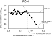
- such a characteristic of the strain increment ratio is utilized to assume that the necking has occurred in the notch root 5a at the point where the strain increment ratio r edge deviates from the r-value in the tensile direction during the tensile deformation process, and the strain at the point of relevant deviation is obtained as the necking limit strain.
- the relation between the strain increment ratio r edge and the maximum principal strain after the occurrence of necking is linearly approximated, and the maximum principal strain at the intersection between the relevant approximation straight line and the r-value in the tensile direction is taken as the necking limit strain.
- the present invention is not limited to the above-described method, and the method may use a certain index that identifies the deviation between the strain increment ratio r edge and the r-value.
- a certain index that identifies the deviation between the strain increment ratio r edge and the r-value.
- the ratio of the strain increment ratio r edge to the r-value is used as an index, the maximum principal strain at the time when the relevant index becomes a predetermined value or less, for example, below 1, only needs to be taken as the necking limit strain.
- the necking limit strain identification step S7 is a step of identifying the necking limit strain as a function of strain gradient from the relation between the necking limit strain obtained for the two or more types of sheet specimens 1 and the strain gradient at the time of the necking limit strain in the tensile deformation process.
- FIG. 5 illustrates a graph for which the necking limit strain obtained for five types of sheet specimens 1 (type A through type E) illustrated in FIG. 6 and the strain gradient at the time when the notch root 5a in each sheet specimen 1 is at the necking limit strain during the tensile deformation process are plotted.
- the sheet specimens 1 illustrated in FIG. 6 all have the semicircular notch geometry 5 in the sheet edge 3, and the notch radius R and/or the ligament length L of the notch geometry 5 is changed so that the strain gradient in the tensile orthogonal direction from the notch root 5a inward is different.
- the range below the necking limit strain [Y] identified as the function of the strain gradient [X] indicates a press formable range in which press forming can be performed without causing necking.
- a press forming simulation of a press forming product accompanied with stretch flanging is performed by a finite element method, and by applying the strain ⁇ FEM and the strain gradient d ⁇ /dx FEM calculated by FEM analysis to the graph of the necking limit strain and the strain gradient in FIG. 5 , it is possible to make a judgement whether press forming is feasible without causing necking.
- the strain ⁇ FEM obtained by the FEM analysis is compared with the value f(d ⁇ /dx FEM ) obtained by substituting the strain gradient d ⁇ /dx FEM at the position where the relevant strain was obtained into the evaluation function f(X) of the necking limit strain [X]. Then, it can be judged that forming is feasible as necking does not occur if ⁇ FEM ⁇ f(d ⁇ /dx FEM ), and that forming is not feasible as the necking occurs if ⁇ FEM > f(d ⁇ /dx FEM ).
- the necking limit strain that causes necking due to tensile deformation imparted to the sheet edge of the metal sheet can be identified easily and accurately, without the need of a plurality of dedicated tools and test devices.
- the method for identifying a necking limit strain of a metal sheet in the present embodiment based on the analysis result of the press forming simulation of the press forming product accompanied with stretch flanging, it is possible to predict the presence of occurrence of necking at a site subjected to stretch flanging and to deal with before leading to the fracture. It is also possible to prevent the fracture due to variations and the like in disturbances during the mass production stage of the relevant press forming product.
- the notch geometry 5 formed in the sheet specimen 1 has been semicircular as illustrated in FIG. 2 .
- it is not limited to the notch geometry 5, and it may be a horizontally long semi-elliptical shape in which the short axis side is notched inward as illustrated in FIG. 7(a) , a vertically long semi-elliptical shape in which the long axis side is notched inward as illustrated in FIG. 7(b) , or a substantially triangular shape in which one apex located inside is rounded with a predetermined notch radius R as illustrated in FIG. 7(c) , for example.
- It may be any shape as long as it can cause necking by imparting tensile deformation to the notch root 5a and can change the strain gradient in the notch root 5a.
- tensile deformation has been imparted to the notch root 5a by applying a tensile load in the in-plane uniaxial direction of the sheet specimen 1 using a uniaxial tensile testing machine, but the method of imparting the tensile deformation is not limited thereto. It may be a method in which the sheet edge on the side having the notch root 5a is supported by two or more points across the notch root 5a, the sheet edge on the opposite side of the notch root 5a is pressed, and a load that results in bending deformation in the plane of the sheet specimen 1 is applied, thereby imparting local tensile deformation to the notch root 5a.
- the sheet specimen only needs to be a metal sheet, and specific examples thereof include a steel sheet, aluminum alloy sheet, magnesium alloy sheet, titanium alloy sheet, and the like. There are no restrictions on the material strength of the sheet specimen 1.
- the occurrence of necking when tensile deformation is imparted to the sheet edge of a sheet specimen, at the notch root 5a, is affected by the end face properties of the metal sheet due to differences in processing at the time of producing the sheet specimens such as piercing or shearing. Therefore, in the present invention, it is preferable to use a sheet specimen that has been fabricated so that the end face properties of the notch root 5a are the same by processing such as piercing or shearing in the same manner as blanks provided for press forming of actual press forming products.
- the present invention may also target identifying the necking limit strain of the necking that occurs at the hole edge formed in a burring process.
- Table 1 indicates the results of the strain gradient and the necking limit strain obtained for each of the five types of sheet specimens 1 fabricated from the steel grade ⁇ .
- Table 2 indicates the results of the strain gradient and the necking limit strain obtained for each of the three types of sheet specimens 1 fabricated from the steel grade ⁇ .
- Table 1 and Table 2 The strain gradients indicated in Table 1 and Table 2 were calculated by dividing the difference between the strain at the notch root 5a of the notch geometry 5 and the strain at a distance of 5 mm inward from the notch root 5a in the tensile orthogonal direction by the distance thereof.
- Table 2 Sheet specimen [steel grade ⁇ ] ( Fig. 6 ) Strain gradient Necking limit strain Type B 0.0205 0.158 Type D 0.0163 0.113 Type E 0.0390 0.230
- FIG. 8 and FIG. 9 indicate the results for which the relation between the necking limit strain and the strain gradient obtained for each of the steel grade ⁇ and the steel grade ⁇ was plotted and the evaluation function f(X) in which the parameters a and b obtained from the relation between the necking limit strain and the strain gradient were given was stated.
- the necking limit strain on a stretch flanging portion of a press forming product 11 illustrated in FIG. 10 was identified by the present invention, and based on the relevant identified necking limit strain, the press forming feasibility was judged. Note that in the actual press forming, a fracture occurred in the site P, while the site Q was formed normally.
- FIG. 11 indicates the evaluation function (solid line in FIG. 11 ) of the necking limit strain identified on the steel grade ⁇ described as an inventive example in the foregoing, the strain gradient obtained in the same manner as those in Table 1 and Table 2 from the strain distribution in the in-plane direction extending from the sheet edge portion toward the bottom portion of the stretch flanging dent in the site P and the site Q obtained by the FEM analysis of the press forming product 11, and the maximum principal strain ( ⁇ marks in FIG. 11 ) corresponding thereto.
- the strain gradients were calculated by dividing the difference between the strain at the notch root 5a and the strain at a distance of 5 mm inward from the notch root 5a in the tensile orthogonal direction by the distance thereof.
- Table 3 collectively indicates the maximum principal strain ⁇ FEM at the site P and the site Q, the strain gradient d ⁇ /dx FEM calculated using the difference between the strain at the notch root 5a and the strain at the position 5 mm inward in the tensile direction from the notch root 5a, the necking limit strain f(d ⁇ /dx FEM ) calculated by giving the strain gradient d ⁇ /dx FEM , and the results for which the press forming feasibility was judged by the relevant obtained necking limit strain.
- the present invention can, on press forming products having a site subjected to stretch flanging, based on the necking limit strain identified using strain gradient, make a judgement of press forming feasibility.
- the present invention it is possible to provide a method for identifying a necking limit strain of a metal sheet that is capable of identifying necking limit strain at the time when necking occurred at the sheet edge of the metal sheet in press forming accompanied with stretch flanging easily and accurately, and capable of predicting the occurrence of fracture in advance during the mass production.
Landscapes
- Engineering & Computer Science (AREA)
- Mechanical Engineering (AREA)
- General Health & Medical Sciences (AREA)
- Chemical & Material Sciences (AREA)
- Analytical Chemistry (AREA)
- Biochemistry (AREA)
- Physics & Mathematics (AREA)
- General Physics & Mathematics (AREA)
- Immunology (AREA)
- Pathology (AREA)
- Life Sciences & Earth Sciences (AREA)
- Health & Medical Sciences (AREA)
- Shaping Metal By Deep-Drawing, Or The Like (AREA)
- Investigating Strength Of Materials By Application Of Mechanical Stress (AREA)
Applications Claiming Priority (2)
| Application Number | Priority Date | Filing Date | Title |
|---|---|---|---|
| JP2020068751A JP6919742B1 (ja) | 2020-04-07 | 2020-04-07 | 金属板のくびれ限界ひずみ特定方法 |
| PCT/JP2020/044709 WO2021205693A1 (fr) | 2020-04-07 | 2020-12-01 | Procédé pour l'identification d'allongement limite de constriction de plaque métallique |
Publications (2)
| Publication Number | Publication Date |
|---|---|
| EP4134183A1 true EP4134183A1 (fr) | 2023-02-15 |
| EP4134183A4 EP4134183A4 (fr) | 2023-09-27 |
Family
ID=77269464
Family Applications (1)
| Application Number | Title | Priority Date | Filing Date |
|---|---|---|---|
| EP20930236.3A Pending EP4134183A4 (fr) | 2020-04-07 | 2020-12-01 | Procédé pour l'identification d'allongement limite de constriction de plaque métallique |
Country Status (7)
| Country | Link |
|---|---|
| US (1) | US20230152195A1 (fr) |
| EP (1) | EP4134183A4 (fr) |
| JP (1) | JP6919742B1 (fr) |
| KR (1) | KR20220146642A (fr) |
| CN (1) | CN115427166A (fr) |
| MX (1) | MX2022012446A (fr) |
| WO (1) | WO2021205693A1 (fr) |
Family Cites Families (5)
| Publication number | Priority date | Publication date | Assignee | Title |
|---|---|---|---|---|
| US8990028B2 (en) * | 2006-02-01 | 2015-03-24 | Nippon Steel & Sumitomo Metal Corporation | Fracture prediction method, device, a program arrangement and computer-accessible medium therefor |
| JP5435352B2 (ja) | 2010-01-08 | 2014-03-05 | 新日鐵住金株式会社 | 板状材料の破断ひずみ特定方法 |
| JP5472518B1 (ja) | 2012-11-19 | 2014-04-16 | Jfeスチール株式会社 | 伸びフランジの限界ひずみ特定方法およびプレス成形可否判定方法 |
| JP7110976B2 (ja) * | 2017-12-27 | 2022-08-02 | 日本製鉄株式会社 | 成形性評価方法、プログラム及び記録媒体 |
| JP6958521B2 (ja) * | 2018-09-14 | 2021-11-02 | Jfeスチール株式会社 | 応力−ひずみ関係推定方法 |
-
2020
- 2020-04-07 JP JP2020068751A patent/JP6919742B1/ja active Active
- 2020-12-01 US US17/916,698 patent/US20230152195A1/en active Pending
- 2020-12-01 WO PCT/JP2020/044709 patent/WO2021205693A1/fr unknown
- 2020-12-01 EP EP20930236.3A patent/EP4134183A4/fr active Pending
- 2020-12-01 KR KR1020227034495A patent/KR20220146642A/ko unknown
- 2020-12-01 MX MX2022012446A patent/MX2022012446A/es unknown
- 2020-12-01 CN CN202080099468.4A patent/CN115427166A/zh active Pending
Also Published As
| Publication number | Publication date |
|---|---|
| MX2022012446A (es) | 2022-10-27 |
| JP2021164933A (ja) | 2021-10-14 |
| JP6919742B1 (ja) | 2021-08-18 |
| EP4134183A4 (fr) | 2023-09-27 |
| WO2021205693A1 (fr) | 2021-10-14 |
| CN115427166A (zh) | 2022-12-02 |
| US20230152195A1 (en) | 2023-05-18 |
| KR20220146642A (ko) | 2022-11-01 |
Similar Documents
| Publication | Publication Date | Title |
|---|---|---|
| Keeler | Circular grid system—a valuable aid for evaluating sheet metal formability | |
| Wang et al. | Measuring forming limit strains with digital image correlation analysis | |
| EP2921841B1 (fr) | Procédé de détermination de la contrainte limite d'emboutissage par étirage et procédé d'évaluation de la faisabilité d'un formage à la presse | |
| Kishor et al. | Optimization of initial blank shape to minimize earing in deep drawing using finite element method | |
| Traphöner et al. | Influence of manufacturing processes on material characterization with the grooved in-plane torsion test | |
| Frącz et al. | Aspects of verification and optimization of sheet metal numerical simulations process using the photogrammetric system | |
| EP4134183A1 (fr) | Procédé pour l'identification d'allongement limite de constriction de plaque métallique | |
| RU2324918C1 (ru) | Способ оценки предельной деформации при локальной листовой штамповке | |
| Pepelnjak et al. | Computer-assisted engineering determination of the formability limit for thin sheet metals by a modified Marciniak method | |
| Ramzi et al. | Numerical prediction of the forming limit diagrams of thin sheet metal using SPIF tests | |
| Luo et al. | Numerical Analysis of AHSS Fracture in a Stretch‐bending Test | |
| US6564646B1 (en) | Measuring method for determining the biaxial shaping behavior of metallic materials, more particularly sheet metal | |
| An et al. | Failure orientation in stretch forming and its correlation with a polycrystal plasticity-based material model for a collection of highly formable sheet steels | |
| Green et al. | A visual technique to determine the forming limit for sheet materials | |
| Sriram et al. | Comparison of forming limit curves for advanced high strength steels using different techniques | |
| Kim et al. | Development of an index model for oil canning of steel sheet metal forming products | |
| Frohn-Sörensen et al. | A Critical Evaluation of Forming Limit Curves Regarding Layout of Bending Processes | |
| JP6773255B1 (ja) | 曲げ割れ評価方法、曲げ割れ評価システム、及びプレス成形部品の製造方法 | |
| Lumelskyj et al. | Comparison of two methods for detection of strain localization in sheet forming | |
| Date et al. | Determining a threshold Strain Nonuniformity Index (SNI) to predict failure in sheet metal components | |
| Lopes et al. | Sheet Metal forming simulation and experimental validation using defined benchmarks | |
| Miles | Formability testing of sheet metals | |
| Saravanan et al. | REVIEW–METHODS AND MEASUREMENTS OF SPRINGBACK EVALUATION | |
| Kesvarakul et al. | Applying 2k Factorial Design to Study on Parameters Affecting Springback of Forming of Advanced High Strength Steel Sheets (AHSS) | |
| Schaeffler | Analysis of Sheet Forming Failures |
Legal Events
| Date | Code | Title | Description |
|---|---|---|---|
| STAA | Information on the status of an ep patent application or granted ep patent |
Free format text: STATUS: THE INTERNATIONAL PUBLICATION HAS BEEN MADE |
|
| PUAI | Public reference made under article 153(3) epc to a published international application that has entered the european phase |
Free format text: ORIGINAL CODE: 0009012 |
|
| STAA | Information on the status of an ep patent application or granted ep patent |
Free format text: STATUS: REQUEST FOR EXAMINATION WAS MADE |
|
| 17P | Request for examination filed |
Effective date: 20221004 |
|
| AK | Designated contracting states |
Kind code of ref document: A1 Designated state(s): AL AT BE BG CH CY CZ DE DK EE ES FI FR GB GR HR HU IE IS IT LI LT LU LV MC MK MT NL NO PL PT RO RS SE SI SK SM TR |
|
| DAV | Request for validation of the european patent (deleted) | ||
| DAX | Request for extension of the european patent (deleted) | ||
| A4 | Supplementary search report drawn up and despatched |
Effective date: 20230824 |
|
| RIC1 | Information provided on ipc code assigned before grant |
Ipc: G01N 3/08 20060101ALI20230818BHEP Ipc: G01N 3/00 20060101ALI20230818BHEP Ipc: B21D 22/00 20060101AFI20230818BHEP |