EP4134058B1 - Exoskelettgelenkselbstsperrmechanismus, kniegelenk und bionischer rehabilitationsroboter - Google Patents
Exoskelettgelenkselbstsperrmechanismus, kniegelenk und bionischer rehabilitationsroboter Download PDFInfo
- Publication number
- EP4134058B1 EP4134058B1 EP21873821.9A EP21873821A EP4134058B1 EP 4134058 B1 EP4134058 B1 EP 4134058B1 EP 21873821 A EP21873821 A EP 21873821A EP 4134058 B1 EP4134058 B1 EP 4134058B1
- Authority
- EP
- European Patent Office
- Prior art keywords
- locking
- rotating frame
- exoskeleton
- base
- rotating
- Prior art date
- Legal status (The legal status is an assumption and is not a legal conclusion. Google has not performed a legal analysis and makes no representation as to the accuracy of the status listed.)
- Active
Links
Images


Classifications
-
- A—HUMAN NECESSITIES
- A61—MEDICAL OR VETERINARY SCIENCE; HYGIENE
- A61H—PHYSICAL THERAPY APPARATUS, e.g. DEVICES FOR LOCATING OR STIMULATING REFLEX POINTS IN THE BODY; ARTIFICIAL RESPIRATION; MASSAGE; BATHING DEVICES FOR SPECIAL THERAPEUTIC OR HYGIENIC PURPOSES OR SPECIFIC PARTS OF THE BODY
- A61H1/00—Apparatus for passive exercising; Vibrating apparatus; Chiropractic devices, e.g. body impacting devices, external devices for briefly extending or aligning unbroken bones
- A61H1/02—Stretching or bending or torsioning apparatus for exercising
- A61H1/0237—Stretching or bending or torsioning apparatus for exercising for the lower limbs
- A61H1/0255—Both knee and hip of a patient, e.g. in supine or sitting position, the feet being moved together in a plane substantially parallel to the body-symmetrical plane
- A61H1/0262—Walking movement; Appliances for aiding disabled persons to walk
-
- A—HUMAN NECESSITIES
- A61—MEDICAL OR VETERINARY SCIENCE; HYGIENE
- A61F—FILTERS IMPLANTABLE INTO BLOOD VESSELS; PROSTHESES; DEVICES PROVIDING PATENCY TO, OR PREVENTING COLLAPSING OF, TUBULAR STRUCTURES OF THE BODY, e.g. STENTS; ORTHOPAEDIC, NURSING OR CONTRACEPTIVE DEVICES; FOMENTATION; TREATMENT OR PROTECTION OF EYES OR EARS; BANDAGES, DRESSINGS OR ABSORBENT PADS; FIRST-AID KITS
- A61F5/00—Orthopaedic methods or devices for non-surgical treatment of bones or joints; Nursing devices ; Anti-rape devices
-
- A—HUMAN NECESSITIES
- A61—MEDICAL OR VETERINARY SCIENCE; HYGIENE
- A61H—PHYSICAL THERAPY APPARATUS, e.g. DEVICES FOR LOCATING OR STIMULATING REFLEX POINTS IN THE BODY; ARTIFICIAL RESPIRATION; MASSAGE; BATHING DEVICES FOR SPECIAL THERAPEUTIC OR HYGIENIC PURPOSES OR SPECIFIC PARTS OF THE BODY
- A61H1/00—Apparatus for passive exercising; Vibrating apparatus; Chiropractic devices, e.g. body impacting devices, external devices for briefly extending or aligning unbroken bones
- A61H1/02—Stretching or bending or torsioning apparatus for exercising
- A61H1/0237—Stretching or bending or torsioning apparatus for exercising for the lower limbs
- A61H1/024—Knee
-
- A—HUMAN NECESSITIES
- A61—MEDICAL OR VETERINARY SCIENCE; HYGIENE
- A61H—PHYSICAL THERAPY APPARATUS, e.g. DEVICES FOR LOCATING OR STIMULATING REFLEX POINTS IN THE BODY; ARTIFICIAL RESPIRATION; MASSAGE; BATHING DEVICES FOR SPECIAL THERAPEUTIC OR HYGIENIC PURPOSES OR SPECIFIC PARTS OF THE BODY
- A61H1/00—Apparatus for passive exercising; Vibrating apparatus; Chiropractic devices, e.g. body impacting devices, external devices for briefly extending or aligning unbroken bones
- A61H1/02—Stretching or bending or torsioning apparatus for exercising
- A61H1/0237—Stretching or bending or torsioning apparatus for exercising for the lower limbs
- A61H1/0266—Foot
-
- A—HUMAN NECESSITIES
- A61—MEDICAL OR VETERINARY SCIENCE; HYGIENE
- A61H—PHYSICAL THERAPY APPARATUS, e.g. DEVICES FOR LOCATING OR STIMULATING REFLEX POINTS IN THE BODY; ARTIFICIAL RESPIRATION; MASSAGE; BATHING DEVICES FOR SPECIAL THERAPEUTIC OR HYGIENIC PURPOSES OR SPECIFIC PARTS OF THE BODY
- A61H3/00—Appliances for aiding patients or disabled persons to walk about
-
- B—PERFORMING OPERATIONS; TRANSPORTING
- B25—HAND TOOLS; PORTABLE POWER-DRIVEN TOOLS; MANIPULATORS
- B25J—MANIPULATORS; CHAMBERS PROVIDED WITH MANIPULATION DEVICES
- B25J17/00—Joints
-
- B—PERFORMING OPERATIONS; TRANSPORTING
- B25—HAND TOOLS; PORTABLE POWER-DRIVEN TOOLS; MANIPULATORS
- B25J—MANIPULATORS; CHAMBERS PROVIDED WITH MANIPULATION DEVICES
- B25J17/00—Joints
- B25J17/02—Wrist joints
-
- B—PERFORMING OPERATIONS; TRANSPORTING
- B25—HAND TOOLS; PORTABLE POWER-DRIVEN TOOLS; MANIPULATORS
- B25J—MANIPULATORS; CHAMBERS PROVIDED WITH MANIPULATION DEVICES
- B25J19/00—Accessories fitted to manipulators, e.g. for monitoring, for viewing; Safety devices combined with or specially adapted for use in connection with manipulators
- B25J19/0004—Braking devices
-
- B—PERFORMING OPERATIONS; TRANSPORTING
- B25—HAND TOOLS; PORTABLE POWER-DRIVEN TOOLS; MANIPULATORS
- B25J—MANIPULATORS; CHAMBERS PROVIDED WITH MANIPULATION DEVICES
- B25J9/00—Programme-controlled manipulators
- B25J9/0006—Exoskeletons, i.e. resembling a human figure
-
- F—MECHANICAL ENGINEERING; LIGHTING; HEATING; WEAPONS; BLASTING
- F16—ENGINEERING ELEMENTS AND UNITS; GENERAL MEASURES FOR PRODUCING AND MAINTAINING EFFECTIVE FUNCTIONING OF MACHINES OR INSTALLATIONS; THERMAL INSULATION IN GENERAL
- F16D—COUPLINGS FOR TRANSMITTING ROTATION; CLUTCHES; BRAKES
- F16D51/00—Brakes with outwardly-movable braking members co-operating with the inner surface of a drum or the like
- F16D51/16—Brakes with outwardly-movable braking members co-operating with the inner surface of a drum or the like shaped as brake-shoes pivoted on a fixed or nearly-fixed axis
- F16D51/18—Brakes with outwardly-movable braking members co-operating with the inner surface of a drum or the like shaped as brake-shoes pivoted on a fixed or nearly-fixed axis with two brake-shoes
- F16D51/20—Brakes with outwardly-movable braking members co-operating with the inner surface of a drum or the like shaped as brake-shoes pivoted on a fixed or nearly-fixed axis with two brake-shoes extending in opposite directions from their pivots
-
- A—HUMAN NECESSITIES
- A61—MEDICAL OR VETERINARY SCIENCE; HYGIENE
- A61H—PHYSICAL THERAPY APPARATUS, e.g. DEVICES FOR LOCATING OR STIMULATING REFLEX POINTS IN THE BODY; ARTIFICIAL RESPIRATION; MASSAGE; BATHING DEVICES FOR SPECIAL THERAPEUTIC OR HYGIENIC PURPOSES OR SPECIFIC PARTS OF THE BODY
- A61H3/00—Appliances for aiding patients or disabled persons to walk about
- A61H2003/005—Appliances for aiding patients or disabled persons to walk about with knee, leg or stump rests
-
- A—HUMAN NECESSITIES
- A61—MEDICAL OR VETERINARY SCIENCE; HYGIENE
- A61H—PHYSICAL THERAPY APPARATUS, e.g. DEVICES FOR LOCATING OR STIMULATING REFLEX POINTS IN THE BODY; ARTIFICIAL RESPIRATION; MASSAGE; BATHING DEVICES FOR SPECIAL THERAPEUTIC OR HYGIENIC PURPOSES OR SPECIFIC PARTS OF THE BODY
- A61H3/00—Appliances for aiding patients or disabled persons to walk about
- A61H2003/007—Appliances for aiding patients or disabled persons to walk about secured to the patient, e.g. with belts
-
- A—HUMAN NECESSITIES
- A61—MEDICAL OR VETERINARY SCIENCE; HYGIENE
- A61H—PHYSICAL THERAPY APPARATUS, e.g. DEVICES FOR LOCATING OR STIMULATING REFLEX POINTS IN THE BODY; ARTIFICIAL RESPIRATION; MASSAGE; BATHING DEVICES FOR SPECIAL THERAPEUTIC OR HYGIENIC PURPOSES OR SPECIFIC PARTS OF THE BODY
- A61H2201/00—Characteristics of apparatus not provided for in the preceding codes
- A61H2201/01—Constructive details
- A61H2201/0192—Specific means for adjusting dimensions
-
- A—HUMAN NECESSITIES
- A61—MEDICAL OR VETERINARY SCIENCE; HYGIENE
- A61H—PHYSICAL THERAPY APPARATUS, e.g. DEVICES FOR LOCATING OR STIMULATING REFLEX POINTS IN THE BODY; ARTIFICIAL RESPIRATION; MASSAGE; BATHING DEVICES FOR SPECIAL THERAPEUTIC OR HYGIENIC PURPOSES OR SPECIFIC PARTS OF THE BODY
- A61H2201/00—Characteristics of apparatus not provided for in the preceding codes
- A61H2201/12—Driving means
- A61H2201/1207—Driving means with electric or magnetic drive
- A61H2201/1215—Rotary drive
-
- A—HUMAN NECESSITIES
- A61—MEDICAL OR VETERINARY SCIENCE; HYGIENE
- A61H—PHYSICAL THERAPY APPARATUS, e.g. DEVICES FOR LOCATING OR STIMULATING REFLEX POINTS IN THE BODY; ARTIFICIAL RESPIRATION; MASSAGE; BATHING DEVICES FOR SPECIAL THERAPEUTIC OR HYGIENIC PURPOSES OR SPECIFIC PARTS OF THE BODY
- A61H2201/00—Characteristics of apparatus not provided for in the preceding codes
- A61H2201/14—Special force transmission means, i.e. between the driving means and the interface with the user
- A61H2201/1454—Special bearing arrangements
-
- A—HUMAN NECESSITIES
- A61—MEDICAL OR VETERINARY SCIENCE; HYGIENE
- A61H—PHYSICAL THERAPY APPARATUS, e.g. DEVICES FOR LOCATING OR STIMULATING REFLEX POINTS IN THE BODY; ARTIFICIAL RESPIRATION; MASSAGE; BATHING DEVICES FOR SPECIAL THERAPEUTIC OR HYGIENIC PURPOSES OR SPECIFIC PARTS OF THE BODY
- A61H2201/00—Characteristics of apparatus not provided for in the preceding codes
- A61H2201/14—Special force transmission means, i.e. between the driving means and the interface with the user
- A61H2201/1463—Special speed variation means, i.e. speed reducer
- A61H2201/1472—Planetary gearing
-
- A—HUMAN NECESSITIES
- A61—MEDICAL OR VETERINARY SCIENCE; HYGIENE
- A61H—PHYSICAL THERAPY APPARATUS, e.g. DEVICES FOR LOCATING OR STIMULATING REFLEX POINTS IN THE BODY; ARTIFICIAL RESPIRATION; MASSAGE; BATHING DEVICES FOR SPECIAL THERAPEUTIC OR HYGIENIC PURPOSES OR SPECIFIC PARTS OF THE BODY
- A61H2201/00—Characteristics of apparatus not provided for in the preceding codes
- A61H2201/16—Physical interface with patient
- A61H2201/1602—Physical interface with patient kind of interface, e.g. head rest, knee support or lumbar support
- A61H2201/164—Feet or leg, e.g. pedal
- A61H2201/1642—Holding means therefor
-
- A—HUMAN NECESSITIES
- A61—MEDICAL OR VETERINARY SCIENCE; HYGIENE
- A61H—PHYSICAL THERAPY APPARATUS, e.g. DEVICES FOR LOCATING OR STIMULATING REFLEX POINTS IN THE BODY; ARTIFICIAL RESPIRATION; MASSAGE; BATHING DEVICES FOR SPECIAL THERAPEUTIC OR HYGIENIC PURPOSES OR SPECIFIC PARTS OF THE BODY
- A61H2201/00—Characteristics of apparatus not provided for in the preceding codes
- A61H2201/16—Physical interface with patient
- A61H2201/1602—Physical interface with patient kind of interface, e.g. head rest, knee support or lumbar support
- A61H2201/165—Wearable interfaces
-
- A—HUMAN NECESSITIES
- A61—MEDICAL OR VETERINARY SCIENCE; HYGIENE
- A61H—PHYSICAL THERAPY APPARATUS, e.g. DEVICES FOR LOCATING OR STIMULATING REFLEX POINTS IN THE BODY; ARTIFICIAL RESPIRATION; MASSAGE; BATHING DEVICES FOR SPECIAL THERAPEUTIC OR HYGIENIC PURPOSES OR SPECIFIC PARTS OF THE BODY
- A61H2201/00—Characteristics of apparatus not provided for in the preceding codes
- A61H2201/16—Physical interface with patient
- A61H2201/1657—Movement of interface, i.e. force application means
- A61H2201/1659—Free spatial automatic movement of interface within a working area, e.g. Robot
-
- A—HUMAN NECESSITIES
- A61—MEDICAL OR VETERINARY SCIENCE; HYGIENE
- A61H—PHYSICAL THERAPY APPARATUS, e.g. DEVICES FOR LOCATING OR STIMULATING REFLEX POINTS IN THE BODY; ARTIFICIAL RESPIRATION; MASSAGE; BATHING DEVICES FOR SPECIAL THERAPEUTIC OR HYGIENIC PURPOSES OR SPECIFIC PARTS OF THE BODY
- A61H2201/00—Characteristics of apparatus not provided for in the preceding codes
- A61H2201/16—Physical interface with patient
- A61H2201/1657—Movement of interface, i.e. force application means
- A61H2201/1664—Movement of interface, i.e. force application means linear
-
- A—HUMAN NECESSITIES
- A61—MEDICAL OR VETERINARY SCIENCE; HYGIENE
- A61H—PHYSICAL THERAPY APPARATUS, e.g. DEVICES FOR LOCATING OR STIMULATING REFLEX POINTS IN THE BODY; ARTIFICIAL RESPIRATION; MASSAGE; BATHING DEVICES FOR SPECIAL THERAPEUTIC OR HYGIENIC PURPOSES OR SPECIFIC PARTS OF THE BODY
- A61H2201/00—Characteristics of apparatus not provided for in the preceding codes
- A61H2201/16—Physical interface with patient
- A61H2201/1657—Movement of interface, i.e. force application means
- A61H2201/1671—Movement of interface, i.e. force application means rotational
-
- A—HUMAN NECESSITIES
- A61—MEDICAL OR VETERINARY SCIENCE; HYGIENE
- A61H—PHYSICAL THERAPY APPARATUS, e.g. DEVICES FOR LOCATING OR STIMULATING REFLEX POINTS IN THE BODY; ARTIFICIAL RESPIRATION; MASSAGE; BATHING DEVICES FOR SPECIAL THERAPEUTIC OR HYGIENIC PURPOSES OR SPECIFIC PARTS OF THE BODY
- A61H2201/00—Characteristics of apparatus not provided for in the preceding codes
- A61H2201/16—Physical interface with patient
- A61H2201/1657—Movement of interface, i.e. force application means
- A61H2201/1676—Pivoting
-
- A—HUMAN NECESSITIES
- A61—MEDICAL OR VETERINARY SCIENCE; HYGIENE
- A61H—PHYSICAL THERAPY APPARATUS, e.g. DEVICES FOR LOCATING OR STIMULATING REFLEX POINTS IN THE BODY; ARTIFICIAL RESPIRATION; MASSAGE; BATHING DEVICES FOR SPECIAL THERAPEUTIC OR HYGIENIC PURPOSES OR SPECIFIC PARTS OF THE BODY
- A61H2201/00—Characteristics of apparatus not provided for in the preceding codes
- A61H2201/50—Control means thereof
- A61H2201/5007—Control means thereof computer controlled
-
- A—HUMAN NECESSITIES
- A61—MEDICAL OR VETERINARY SCIENCE; HYGIENE
- A61H—PHYSICAL THERAPY APPARATUS, e.g. DEVICES FOR LOCATING OR STIMULATING REFLEX POINTS IN THE BODY; ARTIFICIAL RESPIRATION; MASSAGE; BATHING DEVICES FOR SPECIAL THERAPEUTIC OR HYGIENIC PURPOSES OR SPECIFIC PARTS OF THE BODY
- A61H2201/00—Characteristics of apparatus not provided for in the preceding codes
- A61H2201/50—Control means thereof
- A61H2201/5058—Sensors or detectors
- A61H2201/5092—Optical sensor
-
- A—HUMAN NECESSITIES
- A61—MEDICAL OR VETERINARY SCIENCE; HYGIENE
- A61H—PHYSICAL THERAPY APPARATUS, e.g. DEVICES FOR LOCATING OR STIMULATING REFLEX POINTS IN THE BODY; ARTIFICIAL RESPIRATION; MASSAGE; BATHING DEVICES FOR SPECIAL THERAPEUTIC OR HYGIENIC PURPOSES OR SPECIFIC PARTS OF THE BODY
- A61H2205/00—Devices for specific parts of the body
- A61H2205/10—Leg
- A61H2205/102—Knee
-
- F—MECHANICAL ENGINEERING; LIGHTING; HEATING; WEAPONS; BLASTING
- F16—ENGINEERING ELEMENTS AND UNITS; GENERAL MEASURES FOR PRODUCING AND MAINTAINING EFFECTIVE FUNCTIONING OF MACHINES OR INSTALLATIONS; THERMAL INSULATION IN GENERAL
- F16D—COUPLINGS FOR TRANSMITTING ROTATION; CLUTCHES; BRAKES
- F16D66/00—Arrangements for monitoring working conditions, e.g. wear, temperature
- F16D2066/003—Position, angle or speed
-
- F—MECHANICAL ENGINEERING; LIGHTING; HEATING; WEAPONS; BLASTING
- F16—ENGINEERING ELEMENTS AND UNITS; GENERAL MEASURES FOR PRODUCING AND MAINTAINING EFFECTIVE FUNCTIONING OF MACHINES OR INSTALLATIONS; THERMAL INSULATION IN GENERAL
- F16D—COUPLINGS FOR TRANSMITTING ROTATION; CLUTCHES; BRAKES
- F16D2121/00—Type of actuator operation force
- F16D2121/18—Electric or magnetic
- F16D2121/24—Electric or magnetic using motors
-
- F—MECHANICAL ENGINEERING; LIGHTING; HEATING; WEAPONS; BLASTING
- F16—ENGINEERING ELEMENTS AND UNITS; GENERAL MEASURES FOR PRODUCING AND MAINTAINING EFFECTIVE FUNCTIONING OF MACHINES OR INSTALLATIONS; THERMAL INSULATION IN GENERAL
- F16D—COUPLINGS FOR TRANSMITTING ROTATION; CLUTCHES; BRAKES
- F16D2125/00—Components of actuators
- F16D2125/18—Mechanical mechanisms
- F16D2125/20—Mechanical mechanisms converting rotation to linear movement or vice versa
- F16D2125/34—Mechanical mechanisms converting rotation to linear movement or vice versa acting in the direction of the axis of rotation
- F16D2125/40—Screw-and-nut
-
- F—MECHANICAL ENGINEERING; LIGHTING; HEATING; WEAPONS; BLASTING
- F16—ENGINEERING ELEMENTS AND UNITS; GENERAL MEASURES FOR PRODUCING AND MAINTAINING EFFECTIVE FUNCTIONING OF MACHINES OR INSTALLATIONS; THERMAL INSULATION IN GENERAL
- F16D—COUPLINGS FOR TRANSMITTING ROTATION; CLUTCHES; BRAKES
- F16D2125/00—Components of actuators
- F16D2125/18—Mechanical mechanisms
- F16D2125/58—Mechanical mechanisms transmitting linear movement
- F16D2125/66—Wedges
Definitions
- the present invention relates to the technical field of medical rehabilitation devices, in particular to an exoskeleton joint self-locking mechanism, a knee joint and a bionic rehabilitation robot.
- rehabilitation therapy has become a new therapeutic discipline to promote the rehabilitation of physical and mental functions of patients and disabled people, and it is also a new technical specialty. Its purpose is to enable people to resume their daily life, study, work and labor, as well as social life as possible, integrate into society and improve their quality of life.
- the wearer presses the switch located elsewhere, and the main control device will send a signal to the node box, and the node box controls an end round bar of the driver to push out upward, after the end round bar is pushed out upwards, the locking pin can be pushed out; at this time, the spring is compressed, and the end of the locking pin is inserted into the locking hole.
- the driver can be powered off. Due to the internal screw structure, the round bar at the end of the driver can realize linear self-locking, that is, the locking pin cannot be retracted.
- the wearer can manually pull the handle to drive the cable steel rope to pull the top post at the lower end of the steel rope to push out the locking pin to realize locking.
- This knee joint structure can only be locked and unlocked by manual or remote control.
- the locking and unlocking of the joint of a patient during walking require frequent human control intervention, without automatic and intelligent control.
- the complicated operation can easily lead to manipulation errors, which can't protect the safety of the wearer.
- the user experience is poor, and it is impossible to realize the high bionics of the human walking state.
- the brake is controlled by an angle sensor, which determines the working state of the brake by sensing the swing amplitude of the wearer's thigh and controls the unlocking and locking of the knee joint.
- This patent belongs to the field of automotive brakes, and particularly discloses an aluminum-alloy wedge-type brake assembly.
- the assembly has a friction piece fixed on inner and outer surfaces of a brake shoe.
- the brake shoe is fixed with a brake drum that is provided with a left brake shoe and a right brake shoe.
- the left brake shoe and the right brake shoe are hinged with a brake soleplate by a pin shaft.
- the left brake shoe and the right brake shoe are provided with a return elastic piece.
- An expander is provided with a wedge-shaped guide block.
- a wedge-shaped rod drives the wedge-shaped rod and a pneumatic mechanism and fixed with the guide block.
- the present invention provides an exoskeleton joint self-locking mechanism according to appended claim 1.
- the present invention has the following technical effects: According to the present invention, the first base and the second base are rotatably installed, and then the first base and the second base are fixed on the limb of the joint, thereby realizing flexible rotation at the joint; then, a mutual friction surface is formed between the rotating outward expanding locking member on the first base and the inner wall of the second base.
- the first rotating frame, the second rotating frame and the first base do not contact or generate self-locking friction force; when turning to a self-locking state, the locking driving member drives the rotating outward expanding locking member to expand outward, so that the friction surface is in contact and self-locked; the driving is progressive, so a magnitude of the friction force is also progressive; the knee joint is locked and unlocked by controlling the friction force so that the unlocking and locking of the knee joint are not completed instantaneously, and it is gradually locked and unlocked with the increase and decrease of friction force, which is more in line with the activity habits of the joint and safer.
- the free ends of the first rotating frame and/or the second rotating frame are provided with a stress slope surface
- the locking driving member is provided with a telescopic locking portion, which has a force applying slope surface
- the force applying slope surface applies force to the stress slope surface along with the telescopic locking portion.
- the free ends of the first rotating frame and the second rotating frame are connected by an elastic return member.
- the present invention also discloses an exoskeleton joint according to claim 6.
- the self-locking mechanism is disposed at the knee joint, which can start the locking driving member to complete the self-locking to assist standing when standing, and can unlock when walking to complete the activities at the knee joint.
- the present invention also discloses an exoskeleton bionic rehabilitation robot according to claim 7.
- the locking driving member can be started to complete self-locking to assist standing when standing, and the activities at the knee joint can be unlocked when walking.
- the exoskeleton bionic rehabilitation robot also includes a control unit, which comprises:
- the distance between the foot and the walking surface is measured to determine whether the leg walks or stands.
- the distance between the ranging sensor and the walking surface is the smallest, then self-locking is performed to assist standing; and when the distance between the ranging sensor and the walking surface becomes larger, it is in the state of walking or preparing to walk, and activities of the knee joint are completely by the progressive unlocking.
- the ranging sensor includes an infrared ranging sensor, a laser ranging sensor, an ultrasonic ranging sensor, and a radar ranging sensor.
- the range sensor is designed to measure the distance between the ankle-foot component and the walking surface to determine whether the leg is standing or lifting from the ground to prepare for walking.
- the measuring turntable by synchronizing the driving shaft with the synchronous shaft, the measuring turntable also rotates, the number of times that the signal transmitter and signal receiver go through the signal marked area and the signal unmasked area till realizing the self-locking state is counted, so that an angle at which the measuring turntable has turned can be read and recorded, which can prevent the excessive rotation of the driving motor from damaging other parts, and can also control the time to reach this angle, so that the speed of self-locking can be controlled, and the bionic real knee joint movement can be improved for comfort and safety.
- the measuring turntable is a raster encoder.
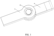
- the first base 1 and the second base 2 are rotatably installed, and then the first base 1 and the second base 2 are fixed on the limb of the joint, thereby realizing flexible rotation at the joint; then, mutual friction surfaces are formed between the rotating outward expanding locking member on the first base 1 and the inner wall of the second base 2.
- the first rotating frame 31, the second rotating frame 32 and the first base do not contact or generate self-locking friction force; when turning to a self-locking state, the locking driving member drives the rotating outward expanding locking member to expand outward, so that the friction surfaces are in contact and self-locked; the driving is progressive, so a magnitude of the friction force is also progressive; the knee joint is locked and unlocked by controlling the friction force, so the unlocking and locking of the knee joint are not completed instantaneously, but gradually locked and unlocked with the increase and decrease of friction force, which is more in line with the activity habits of the joint and safer.
- the design at the joint should favor the space utilization, make the overall component space layout reasonable and compact, and reduce the overall size so that the force applied by the locking driving member is divided and decomposed by two acting surfaces.
- the free ends of the first rotating frame 31 and/or the second rotating frame 32 are provided with a stress slope surface
- the locking driving member is provided with a telescopic locking portion
- the telescopic locking portion has a force applying slope surface 621
- the force applying slope surface 621 applies force to the stress slope surface along with the telescopic locking portion.
- the force applying slope surface 621 applies a force to the stress slope surface to separate the first rotating frame 31 from the second rotating frame 32, so that the overall structure is flattened, which is more suitable for wearing and mounting at the joint.
- the third method works best when implemented in concrete terms - the force applied during self-locking is uniform, and the first rotating frame 31 and the second rotating frame 32 are symmetrically and stably extended, but it does not mean that the first and second methods can't achieve the self-locking effect; although not accompanied by specific illustrations, but those skilled in the art should be able to draw the structure without a doubt.
- the first base 1 is also provided with a chute which is used to cooperate with the telescopic locking portion to achieve telescoping in the sense of mechanical structure.
- the locking driving member is the power of the self-locking mechanism.
- the locking driving member includes a driving motor 61, and the telescopic locking portion is a locking slider 62 disposed in the chute; the driving end of the driving motor 61 is provided with a threaded segment 614, the locking slider 62 is provided with a threaded groove, and the threaded segment 614 is inserted into the threaded groove.
- the locking slider 62 cannot rotate axially along with the threaded segment 614 in the chute, so the threaded segment 614 acts as a lead screw here, and drives the locking slider 62 to reciprocate in the chute by the direction of self-rotation.
- the driving motor 61 is enabled to accurately adjust the rotation of the threaded segment 614 through a reduction gearbox 612, thereby accurately adjusting the advance and retreat of the locking slider 62, so that the whole self-locking process is accurate, smooth and natural.
- the second base 2 is mounted on the first base 1 by a mounting mechanism
- the mounting mechanism comprises a mounting groove, a bearing 52 and a rotating shaft 51.
- the mounting groove is provided on the second base 2, the outer ring of the bearing 52 is fixedly mounted in the mounting groove; the rotating shaft 51 is disposed in the first compartment of the first base 1, and the inner ring of the bearing 52 is fixedly mounted on the rotating shaft 51.
- the mounting groove may also be provided as a through groove described in FIG. 2 , and then the clamp spring 53 is used for further fixed mounting.
- the structure facilitates the relative rotation of the first base 1 and the second base 2 without axial translocation, and the rotation is smooth and stable.
- the free ends of the first rotating frame 31 and the second rotating frame 32 are connected by an elastic return member 34, which helps the first rotating frame and the second rotating frame to quickly disengage from the first base.
- the elastic return member 34 is preferably an extension spring, or an elastic resin or rubber can be selected.
- the purpose of the elastic return member is to reset and stretch the first rotating frame 31 and the second rotating frame 32, and everything that can achieve this purpose should be included in the selection range of the elastic return member.
- the driving motor 61 specifically comprises a miniature DC motor 611, a reduction gearbox 612, and a mounting bearing 613.
- the reduction gearbox 612 is mounted on the miniature DC motor 611, the position of the driving shaft is limited by the mounting bearing 613, and the entire driving motor 61 is mounted in the first base 1 in the form of mounting groove.
- the first base 1 is provided with groove whose shape and position are adapted to the driving motor 61 to fit the mounting limit.
- the driving motor is clamped in the form of groove in the prior art, so a redundant description is not made.
- the present invention also includes an outer cover plate 4, which is mounted on the first base 1 and used to cover the driving motor 61 and other components.
- the outer cover plate 4 is disposed in a "post and slot" manner.
- the first base 1 is provided with a slot, and then the outer cover plate 4 is provided with a post, which is inserted into the slot for limiting, and then a bolt through hole connection or screw punch hole connection is made.
- the present invention has the following technical effects:
- the present invention also provides an exoskeleton knee joint, which comprises a shank connecting rod 8, a thigh connecting rod and the above exoskeleton joint self-locking mechanism.
- the shank connecting rod 8 is connected to the first base 1, and the thigh connecting rod is connected to the second base 2.
- the self-locking mechanism is disposed at the knee joint, which can start the locking driving member to complete the self-locking to assist standing when standing, and can unlock when walking to complete the activities at the knee joint.
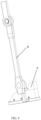
- the present invention also provides an exoskeleton bionic rehabilitation robot, which includes the above exoskeleton knee joint and an ankle-foot component 9, and the ankle-foot component 9 is connected to the shank connecting rod 8 of the exoskeleton knee joint.
- the locking driving member can be started to complete self-locking to assist standing when standing, and the activities at the knee joint can be unlocked when walking.
- the present invention also includes a control unit, which comprises a control motherboard 73 and a ranging sensor 91, wherein the control motherboard 73 is in control connection to the locking driving member; the ranging sensor 91 is provided on the ankle-foot component 9 to measure a distance between the ankle-foot component 9 and the walking surface, and the ranging sensor 91 is in signal connection to the control motherboard 73. The distance between the foot and the walking surface (ground) is measured to determine whether the leg walks or stands.
- the distance between the ranging sensor 91 and the walking surface is the smallest, then self-locking is realized to assist standing; and when the distance between the ranging sensor 91 and the walking surface becomes larger, it is in the state of walking or preparing to walk, and activities of the knee joint are completely by the progressive unlocking.
- the ankle-foot component 9 and the shank connecting rod 8 are also rotationally connected, and the connection mode is similar to that of the first base 1 and the second base 2 in structure.
- a third base 93 is disposed on the shank connecting rod 8
- a fourth base 94 is disposed on the ankle-foot component 9
- an ankle-foot rotating shaft 95 is disposed on the third base 93
- an ankle-foot bearing 96 is disposed on the fourth base 94
- the fourth base 94 is mounted on the third base 93 through the ankle-foot component 9.
- the ranging sensor 91 is mounted at one end of the third base 93 facing the walking surface, and is mounted inside the third base 93, and then fixed with a ranging sensor bracket 92, which does not block the ranging sensing of the ranging sensor 91.
- the present invention also includes a remote control, which is provided with a basic function control module to communicate with the control motherboard 73.
- a remote control which is provided with a basic function control module to communicate with the control motherboard 73.
- the ranging sensor 91 when switching to a "sitting" mode, the ranging sensor 91 is turned off instantly, then the driving motor 61 is automatically reset and the locking slider 62 is retreated to the bottom end, under the action of the elastic return member 34 (extension spring), the first rotating frame 31 and the second rotating frame 32 are rotationally attached along a pivot shaft; at the same time, two brake pads 33 on the first rotating frame 31 and the second rotating frame 32 are driven to rotate and form a clearance fit with the inner wall of the second base 2 of the thigh connecting rod. At this time, the first base 1 and the second base 2 can be unlocked and rotated freely. But the first base 1 and the second base 2 are provided with rotation angle mechanical limits.
- the ranging sensor 91 When the patient is lifted, it switches to a "standing" mode, the ranging sensor 91 is still not turned on, the driving motor 61 works rapidly to push the locking slider 62 to the maximum displacement of the top end, the first rotating frame 31 and the second rotating frame 32 are pushed by the locking slider 62 and quickly open, and at the same time, the two brake pads 33 squeeze and rub the inner wall of the second base 2 and lock the second base 2 and the rotating outward expanding locking member, thereby realizing the locking of the second base 2 and the first base 1, locking the rotational freedom and realizing the patient's assisted standing.
- the ranging sensor 91 When switching to a "walking" mode, the ranging sensor 91 is activated for operation. Before standing and walking, the left and right knee joint self-locking mechanisms are locked and prohibited from rotating to support human body weight. At the beginning of walking, when the center of gravity of the human body moves to the right leg, the left thigh rotates and rises, which drives the shank and ankle joint to rise. The ranging sensor 91 detects a change of an initial distance value, feeds back and starts the driving motor 61 to work in time, and the locking slider 62 returns to drive the brake pad 33 to reset, thus unlocking the left knee joint to complete knee bending. Then, the patient slowly shifts the center of gravity forward to the left leg.
- the left leg's support and the right leg's walking share the same principle of action, so the cycle is repeated to complete the walking action and help the rehabilitation of the patient's lower limbs.
- the ranging sensor 91 includes but is not limited to an infrared ranging sensor 91, a laser ranging sensor 91, an ultrasonic ranging sensor 91 and a radar ranging sensor 91.
- the range sensor 91 is designed to measure the distance between the ankle-foot component and the walking surface to determine whether the leg is standing or lifting from the ground to prepare for walking.
- the measuring turntable By synchronizing the driving shaft with the synchronous shaft 74, the measuring turntable also rotates, the number of times that the signal transmitter and signal receiver go through the signal marked area and a signal unmasked area till realizing the self-locking state is counted, so that an angle at which the measuring turntable has turned can be read and recorded, which can prevent the excessive rotation of the driving motor 61 from damaging other parts, and can also control the time to reach this angle, so that the speed of self-locking can be controlled, and the bionic real knee joint movement can be improved for comfort and safety.
- the signal transmitter and the signal receiver are a set of infrared transceiver photodiode pairs 72.
- the measuring turntable is a raster encoder 71.
- the raster encoder 71 and the infrared transceiver photodiode pairs 72 are introduced for counting, which can give electrical signals when the contact is disconnected or connected through infrared communication.
- the driving motor 61 drives the raster encoder 71 to rotate from the initial position, the infrared communication between the pairs and the raster encoder is blocked every certain rotation angle.
- the rotation angle of the synchronous shaft can be calculated.
- the rotation angle of the synchronous shaft needed to realize complete unlocking and locking of the knee joint can be obtained by calculation or test.
- the unlocking-locking of the knee joint is controlled by the friction force between the brake pad 33 and the inner wall of the second base 2, it is possible to control the magnitude and change rate of this friction force by controlling the feed speed and the feed stroke of the locking slider 62, and to realize the switching between the unlocking, partial locking and locking states of the knee joint.
- a buffer state of partial locking is added between locking and unlocking states; in this state, the friction force is partially retained, the joint rotation rate is limited, the danger caused by sudden state change is eliminated, and the bionic real knee joint movement can be improved for comfort and safety.
- the driving motor 61 is a coaxial motor, and the synchronous shaft 74 and the driving shaft of the driving motor 61 are disposed to be coaxial but at different ends.
- the present invention has the following technical effects:
Landscapes
- Health & Medical Sciences (AREA)
- Engineering & Computer Science (AREA)
- Life Sciences & Earth Sciences (AREA)
- Veterinary Medicine (AREA)
- Public Health (AREA)
- General Health & Medical Sciences (AREA)
- Animal Behavior & Ethology (AREA)
- Pain & Pain Management (AREA)
- Rehabilitation Therapy (AREA)
- Physical Education & Sports Medicine (AREA)
- Epidemiology (AREA)
- Mechanical Engineering (AREA)
- Robotics (AREA)
- Orthopedic Medicine & Surgery (AREA)
- General Engineering & Computer Science (AREA)
- Nursing (AREA)
- Biomedical Technology (AREA)
- Heart & Thoracic Surgery (AREA)
- Vascular Medicine (AREA)
- Rehabilitation Tools (AREA)
Claims (12)
- Selbstsperrender Mechanismus für ein Exoskelettgelenk, umfassend:eine erste Basis (1) mit einer ersten Kammer;ein rotierendes, sich nach außen ausdehnendes Verriegelungselement, das in der ersten Kammer angeordnet ist, wobei das rotierende, sich nach außen ausdehnende Verriegelungselement einen ersten rotierenden Rahmen (31) und einen zweiten rotierenden Rahmen (32) umfasst und die Außenseiten des ersten rotierenden Rahmens (31) und des zweiten rotierenden Rahmens (32) eine erste Reibungsfläche aufweisen; und wobei ein Ende des ersten rotierenden Rahmens (31) mit einem Ende des zweiten rotierenden Rahmens (32) gelenkig verbunden ist und die anderen Enden des ersten rotierenden Rahmens (31) und des zweiten rotierenden Rahmens (32) relativ freie Enden sind;eine zweite Basis (2) mit einer zweiten Kammer, wobei die zweite Basis (2) drehbar an der ersten Basis (1) angebracht ist und eine Innenwand der zweiten Kammer das rotierendes, sich nach außen ausdehnende Verriegelungselement umschließt und eine zweite Reibungsfläche bildet, die mit der ersten Reibungsfläche abgestimmt;ein Verriegelungsantriebselement, das eine Kraft aufbringen/aufheben kann, die von einem freien Ende des ersten rotierenden Rahmens (31) und einem freien Ende des zweiten rotierenden Rahmens (32) wegdrückt, um die erste Reibungsfläche in engen Kontakt zu bringen, um die zweite Reibungsfläche zu verriegeln/entriegeln; wobei ferner das freie Ende des ersten rotierenden Rahmens (31) und/oder das freie Ende des zweiten rotierenden Rahmens (32) mit einer Spannungsschrägfläche (311) versehen ist, wobei das Verriegelungsantriebselement mit einem teleskopischen Verriegelungsabschnitt versehen ist, wobei der teleskopische Verriegelungsabschnitt eine kraftaufbringende Schrägfläche (621) aufweist, und die kraftaufbringende Schrägfläche (621) zusammen mit dem teleskopischen Verriegelungsabschnitt eine Kraft auf die Spannungsschrägfläche (311) ausübt, wobei die erste Basis (1) eine Rutsche umfasst, das Verriegelungsantriebselement einen Antriebsmotor (61) umfasst und der teleskopische Verriegelungsabschnitt ein Verriegelungsschieber (62) ist, der in der Rutsche angeordnet ist; undeinen Verriegelungsmessmechanismus, umfassend:eine Synchronwelle (74), die sich synchron mit einer Antriebswelle des Antriebsmotors (61) dreht;einen Signalsender und einem Signalempfänger, die einander in Abständen gegenüberliegen;einen Messdrehteller, wobei ein Drehpunkt des Messdrehtellers mit der Synchronwelle (74) verbunden ist und ein Kanten des Messdrehtellers beabstandet zyklisch mit einem signalmarkierten Bereich (711) und einem signalunmarkierten Bereich (712) versehen ist; Wobei der Messdrehtisch sich mit der Synchronwelle (74) dreht, um eine Signalverbindung zwischen dem Signalsender und dem Signalempfänger kreisförmig zu blockieren/umzuschalten.
- Selbstsperrender Mechanismus für ein Exoskelettgelenk nach Anspruch 1, dadurch gekennzeichnet, dass ein umgekehrter trapezförmiger Raum zwischen den Spannungsschrägflächen (311) des ersten rotierenden Rahmens (31) und des zweiten rotierenden Rahmens (32) gebildet wird, und dass eine Form des teleskopischen Verriegelungsabschnitts mit dem umgekehrten trapezförmigen Raum übereinstimmt.
- Selbstsperrender Mechanismus für ein Exoskelettgelenk nach Anspruch 1, dadurch gekennzeichnet, dass ein Antriebsende des Antriebsmotors (61) mit einem Gewindesegment (614) versehen ist, der Verriegelungsschieber (62) mit einer Gewindenut versehen ist und das Gewindesegment (614) in die Gewindenut eingesetzt ist.
- Selbstsperrender Mechanismus für ein Exoskelettgelenk nach Anspruch 1, dadurch gekennzeichnet, dass die zweite Basis (2) an der ersten Basis (1) durch einen Befestigungsmechanismus befestigt ist, und der Befestigungsmechanismus umfasst:eine Montagenut, die an der zweiten Basis (2) vorgesehen ist;ein Lager (52), wobei ein Außenring des Lagers (52) fest in der Montagenut montiert ist; undeine Drehwelle (51), die in der ersten Kammer der ersten Basis (1) angeordnet ist und ein Innenring des Lagers (52) fest auf der Drehwelle (51) montiert ist.
- Selbstsperrender Mechanismus für ein Exoskelettgelenk nach Anspruch 1, dadurch gekennzeichnet, dass das freie Ende des ersten rotierenden Rahmens (31) und das freie Ende des zweiten rotierenden Rahmens (32) durch ein elastisches Rückstellelement (34) verbunden sind.
- Exoskelett-Kniegelenk, dadurch gekennzeichnet, dass es eine Unterschenkel-Verbindungsstange (8), eine Oberschenkel-Verbindungsstange und den Selbstsperrender Mechanismus für ein Exoskelettgelenk nach Anspruch 3 umfasst; und die Unterschenkel-Verbindungsstange (8) mit der ersten Basis (1) verbunden ist und die Oberschenkel-Verbindungsstange mit der zweiten Basis (2) verbunden ist.
- Bionischer Exoskelett-Rehabilitationsroboter, dadurch gekennzeichnet, dass er das Exoskelett-Kniegelenk nach Anspruch 6 und eine Knöchel-Fuß-Komponente (9) umfasst, die mit der Unterschenkel-Verbindungsstange (8) des Exoskelett-Kniegelenks verbunden ist.
- Bionischer Exoskelett-Rehabilitationsroboter nach Anspruch 7, dadurch gekennzeichnet, dass der bionische Exoskelett-Rehabilitationsroboter außerdem eine Steuereinheit umfasst, wobei die Steuereinheit umfasst:eine Steuerplatine (73), die in Steuerverbindung mit dem Verriegelungsantriebselement steht; undeinen Entfernungssensor (91), der an der Knöchel-Fuß-Komponente (9) angeordnet ist, um einen Abstand zwischen der Knöchel-Fuß-Komponente (9) und einer Gehoberfläche zu messen, und wobei der Entfernungssensor (91) in Signalverbindung mit der Steuerplatine (73) steht.
- Bionischer Exoskelett-Rehabilitationsroboter nach Anspruch 8, dadurch gekennzeichnet, dass der Entfernungssensor (91) einen Infrarot-Entfernungssensor, einen Laser-Entfernungssensor, einen Ultraschall-Entfernungssensor und einen Radar-Entfernungssensor umfasst.
- Bionischer Exoskelett-Rehabilitationsroboter nach Anspruch 8, dadurch gekennzeichnet, dass der Signalsender und der Signalempfänger ein Satz von Infrarot-Transceiver-Photodiodenpaaren (72) sind.
- Bionischer Exoskelett-Rehabilitationsroboter nach Anspruch 10, dadurch gekennzeichnet, dass der Messdrehtisch ein Raster-Encoder (71) ist.
- Bionischer Exoskelett-Rehabilitationsroboter nach Anspruch 8, dadurch gekennzeichnet, dass der Antriebsmotor (61) ein Koaxialmotor ist und die Synchronwelle (74) und die Antriebswelle des Antriebsmotors (61) koaxial, aber an unterschiedlichen Enden angeordnet sind.
Applications Claiming Priority (2)
| Application Number | Priority Date | Filing Date | Title |
|---|---|---|---|
| CN202011046110.3A CN111920651B (zh) | 2020-09-29 | 2020-09-29 | 一种外骨骼关节自锁机构、膝关节和仿生康复机器人 |
| PCT/CN2021/081710 WO2022068154A1 (zh) | 2020-09-29 | 2021-03-19 | 一种外骨骼关节自锁机构、膝关节和仿生康复机器人 |
Publications (3)
| Publication Number | Publication Date |
|---|---|
| EP4134058A1 EP4134058A1 (de) | 2023-02-15 |
| EP4134058A4 EP4134058A4 (de) | 2024-04-10 |
| EP4134058B1 true EP4134058B1 (de) | 2025-01-22 |
Family
ID=73334758
Family Applications (1)
| Application Number | Title | Priority Date | Filing Date |
|---|---|---|---|
| EP21873821.9A Active EP4134058B1 (de) | 2020-09-29 | 2021-03-19 | Exoskelettgelenkselbstsperrmechanismus, kniegelenk und bionischer rehabilitationsroboter |
Country Status (4)
| Country | Link |
|---|---|
| US (1) | US20230218464A1 (de) |
| EP (1) | EP4134058B1 (de) |
| CN (1) | CN111920651B (de) |
| WO (1) | WO2022068154A1 (de) |
Families Citing this family (16)
| Publication number | Priority date | Publication date | Assignee | Title |
|---|---|---|---|---|
| CN111920651B (zh) * | 2020-09-29 | 2021-02-05 | 上海傅利叶智能科技有限公司 | 一种外骨骼关节自锁机构、膝关节和仿生康复机器人 |
| CN114404043A (zh) * | 2022-01-19 | 2022-04-29 | 北京罗森博特科技有限公司 | 并联机器人系统 |
| CN114888775B (zh) * | 2022-04-24 | 2024-03-05 | 河北工业大学 | 一种适于快速拆卸的外骨骼 |
| CN114770589B (zh) * | 2022-05-26 | 2023-07-07 | 安徽工业大学 | 一种自锁可控柔顺膝关节外骨骼装置 |
| CN114952812B (zh) * | 2022-05-26 | 2025-01-28 | 北京化工大学 | 离合型蜗轮蜗杆式关节驱动机构 |
| EP4543393A1 (de) * | 2022-06-23 | 2025-04-30 | Nanyang Technological University | Gleichgewichtsunterstützende vorrichtung und system |
| US20240075612A1 (en) | 2022-09-02 | 2024-03-07 | Motion Augmented LLC | Modular motor units and methods for making the same for active-passive robotic exoskeleton systems |
| CN115783759A (zh) * | 2022-12-12 | 2023-03-14 | 广东恒鑫智能装备股份有限公司 | 电芯自锁式夹紧机构 |
| CN115844691B (zh) * | 2023-01-20 | 2025-09-05 | 杭州极智医疗科技有限公司 | 关节训练设备 |
| CN115887182B (zh) * | 2023-01-20 | 2025-09-09 | 杭州极智医疗科技有限公司 | 关节训练设备 |
| CN116292539B (zh) * | 2023-03-24 | 2025-08-01 | 安杰莱科技(杭州)有限公司 | 一种快速拆装锁定机构和下肢康复机器人 |
| CN116750464B (zh) * | 2023-08-16 | 2023-11-07 | 江苏人民机具有限公司 | 一种履带板自动翻转装置 |
| CN117565024B (zh) * | 2023-12-27 | 2024-04-16 | 浙江通势达电动技术有限公司 | 一种用于外骨骼机器人的集成式关节驱动装置及方法 |
| CN118161326B (zh) * | 2024-03-20 | 2024-08-20 | 昆山市第一人民医院 | 一种多功能防护用足踝固定支具 |
| CN118288266B (zh) * | 2024-06-06 | 2024-08-20 | 陕西三航科技有限公司 | 人体膝关节助力外骨骼装置 |
| CN119098935B (zh) * | 2024-08-28 | 2025-11-28 | 浙江工业大学 | 一种自适应调整关节旋转中心的髋关节辅助外骨骼机器人 |
Family Cites Families (22)
| Publication number | Priority date | Publication date | Assignee | Title |
|---|---|---|---|---|
| US5282460A (en) * | 1992-01-06 | 1994-02-01 | Joyce Ann Boldt | Three axis mechanical joint for a power assist device |
| JPH06214651A (ja) * | 1993-01-19 | 1994-08-05 | Matsushita Electric Ind Co Ltd | 光学式ロータリエンコーダ |
| CN2203726Y (zh) * | 1994-08-24 | 1995-07-19 | 于学善 | 浮动可调式制动器 |
| CA2252221C (en) * | 1996-04-15 | 2007-07-24 | Giancarlo Pellis | Adjustable rotation radius articulated joint for gym machines and knee tutors |
| CN1286187A (zh) * | 1999-08-31 | 2001-03-07 | 高自强 | 鼓式四蹄八片无切点制动器 |
| CN101083423B (zh) * | 2006-05-29 | 2010-07-14 | 深圳市大族精密机电有限公司 | 振镜电机 |
| ES2547856T3 (es) * | 2007-09-27 | 2015-10-09 | University Of Tsukuba | Aparato y método de regulación de giro para controlar un aparato giratorio |
| WO2009082249A2 (en) * | 2007-12-26 | 2009-07-02 | Richard Little | Mobility aid |
| US20100125229A1 (en) * | 2008-07-11 | 2010-05-20 | University Of Delaware | Controllable Joint Brace |
| CN103260576B (zh) * | 2010-12-16 | 2015-04-22 | 丰田自动车株式会社 | 行走辅助装置 |
| JP6535283B2 (ja) | 2012-09-07 | 2019-06-26 | ザ リージェンツ オブ ザ ユニバーシティ オブ カリフォルニア | 制御可能な非能動性人口膝 |
| JP6149254B2 (ja) * | 2013-06-20 | 2017-06-21 | パナソニックIpマネジメント株式会社 | モータ位置検出器 |
| CN106236517B (zh) * | 2016-08-31 | 2018-09-07 | 中国科学院深圳先进技术研究院 | 外骨骼机器人腿部运动系统 |
| CN106321690B (zh) * | 2016-08-31 | 2019-01-11 | 重庆中帝机械制造股份有限公司 | 铝合金楔式制动器总成 |
| WO2018236225A1 (en) * | 2017-06-20 | 2018-12-27 | Opum Technologies Limited | ORTHESIS OR EXOSQUELET SYSTEM WITH MODULAR ELEMENTS |
| CN206630847U (zh) * | 2017-08-24 | 2017-11-14 | 苏州致康医疗机器人科技有限公司 | 一种外骨骼模块化锁定‑放松关节 |
| CN107928995A (zh) * | 2017-11-22 | 2018-04-20 | 上海理工大学 | 一种基于扭簧离合器的下肢外骨骼膝关节 |
| CN210872826U (zh) | 2019-09-10 | 2020-06-30 | 河北工业大学 | 一种仿人体膝关节运动曲线的穿戴式下肢助行外骨骼 |
| CN210889836U (zh) * | 2019-10-16 | 2020-06-30 | 宁波国达科技有限公司 | 高速悬挂式甩干机制动器 |
| CN111409060A (zh) | 2020-04-07 | 2020-07-14 | 迈宝智能科技(苏州)有限公司 | 能够站立态快速自锁的下肢负重助力外骨骼 |
| US12330293B1 (en) * | 2020-06-29 | 2025-06-17 | Amazon Technologies, Inc. | Braking assembly for applying a controllable braking force to a rotatable joint |
| CN111920651B (zh) * | 2020-09-29 | 2021-02-05 | 上海傅利叶智能科技有限公司 | 一种外骨骼关节自锁机构、膝关节和仿生康复机器人 |
-
2020
- 2020-09-29 CN CN202011046110.3A patent/CN111920651B/zh active Active
-
2021
- 2021-03-19 EP EP21873821.9A patent/EP4134058B1/de active Active
- 2021-03-19 WO PCT/CN2021/081710 patent/WO2022068154A1/zh not_active Ceased
- 2021-03-19 US US17/923,020 patent/US20230218464A1/en active Pending
Also Published As
| Publication number | Publication date |
|---|---|
| CN111920651B (zh) | 2021-02-05 |
| CN111920651A (zh) | 2020-11-13 |
| US20230218464A1 (en) | 2023-07-13 |
| EP4134058A1 (de) | 2023-02-15 |
| WO2022068154A1 (zh) | 2022-04-07 |
| EP4134058A4 (de) | 2024-04-10 |
Similar Documents
| Publication | Publication Date | Title |
|---|---|---|
| EP4134058B1 (de) | Exoskelettgelenkselbstsperrmechanismus, kniegelenk und bionischer rehabilitationsroboter | |
| US9788985B2 (en) | Friction-based orthotic impedence modulation device | |
| CN109172289B (zh) | 基于多功能驱动器的髋关节康复外骨骼及其运动控制方法 | |
| Shamaei et al. | Design and functional evaluation of a quasi-passive compliant stance control knee–ankle–foot orthosis | |
| CN109773755B (zh) | 一种无驱动的穿戴式膝关节助力外骨骼机器人 | |
| CN107811805B (zh) | 穿戴式下肢外骨骼康复机器人 | |
| EP3229687B1 (de) | Angetriebene und passive hilfsvorrichtung und zugehörige verfahren | |
| CN111168648B (zh) | 一种基于柔性驱动的四自由度髋关节外骨骼助行机器人 | |
| CN110974633B (zh) | 一种智能助行康复训练机器人 | |
| CN108095976B (zh) | 一种具有被动回弹功能的仿生膝关节康复训练装置 | |
| CN110292507B (zh) | 一种踝关节助力外骨骼 | |
| CN107252210A (zh) | 一种自动控制的可穿戴座椅及使用方法 | |
| CN103735386A (zh) | 穿戴式下肢外骨骼康复机器人 | |
| TW201639534A (zh) | 外骨骼踝關節機器裝置 | |
| US20230398003A1 (en) | Powered prosthesis with torque dense, low ratio actuation | |
| CN112972209A (zh) | 一种髋膝耦合的被动型储能助力外骨骼 | |
| CN115245446A (zh) | 一种具有刚度调节与能量回收功能的膝关节外骨骼及其训练方法 | |
| CN112515824B (zh) | 一种主被动结合的下肢假肢膝关节 | |
| Chen et al. | Design of a lower extremity exoskeleton for motion assistance in paralyzed individuals | |
| Kang et al. | Design and validation of a torque controllable hip exoskeleton for walking assistance | |
| CN107361999B (zh) | 一种行走式肩关节康复训练机构 | |
| Han et al. | Research on a multimodal actuator-oriented power-assisted knee exoskeleton | |
| CN117045470A (zh) | 一种穿戴式下肢助行外骨骼机器人 | |
| Ma et al. | The development and preliminary test of a powered alternately walking exoskeleton with the wheeled foot for paraplegic patients | |
| Kubasad et al. | A review on designs of various ankle foot orthosis (AFO) used to treat drop foot disease |
Legal Events
| Date | Code | Title | Description |
|---|---|---|---|
| STAA | Information on the status of an ep patent application or granted ep patent |
Free format text: STATUS: THE INTERNATIONAL PUBLICATION HAS BEEN MADE |
|
| PUAI | Public reference made under article 153(3) epc to a published international application that has entered the european phase |
Free format text: ORIGINAL CODE: 0009012 |
|
| STAA | Information on the status of an ep patent application or granted ep patent |
Free format text: STATUS: REQUEST FOR EXAMINATION WAS MADE |
|
| 17P | Request for examination filed |
Effective date: 20221108 |
|
| AK | Designated contracting states |
Kind code of ref document: A1 Designated state(s): AL AT BE BG CH CY CZ DE DK EE ES FI FR GB GR HR HU IE IS IT LI LT LU LV MC MK MT NL NO PL PT RO RS SE SI SK SM TR |
|
| DAV | Request for validation of the european patent (deleted) | ||
| DAX | Request for extension of the european patent (deleted) | ||
| A4 | Supplementary search report drawn up and despatched |
Effective date: 20240314 |
|
| RIC1 | Information provided on ipc code assigned before grant |
Ipc: F16D 51/20 20060101ALI20240307BHEP Ipc: A61F 5/00 20060101ALI20240307BHEP Ipc: B25J 9/00 20060101ALI20240307BHEP Ipc: A61H 1/02 20060101AFI20240307BHEP |
|
| GRAP | Despatch of communication of intention to grant a patent |
Free format text: ORIGINAL CODE: EPIDOSNIGR1 |
|
| STAA | Information on the status of an ep patent application or granted ep patent |
Free format text: STATUS: GRANT OF PATENT IS INTENDED |
|
| INTG | Intention to grant announced |
Effective date: 20240909 |
|
| GRAS | Grant fee paid |
Free format text: ORIGINAL CODE: EPIDOSNIGR3 |
|
| GRAA | (expected) grant |
Free format text: ORIGINAL CODE: 0009210 |
|
| STAA | Information on the status of an ep patent application or granted ep patent |
Free format text: STATUS: THE PATENT HAS BEEN GRANTED |
|
| P01 | Opt-out of the competence of the unified patent court (upc) registered |
Free format text: CASE NUMBER: APP_64474/2024 Effective date: 20241205 |
|
| AK | Designated contracting states |
Kind code of ref document: B1 Designated state(s): AL AT BE BG CH CY CZ DE DK EE ES FI FR GB GR HR HU IE IS IT LI LT LU LV MC MK MT NL NO PL PT RO RS SE SI SK SM TR |
|
| REG | Reference to a national code |
Ref country code: GB Ref legal event code: FG4D |
|
| REG | Reference to a national code |
Ref country code: CH Ref legal event code: EP |
|
| REG | Reference to a national code |
Ref country code: IE Ref legal event code: FG4D |
|
| REG | Reference to a national code |
Ref country code: DE Ref legal event code: R096 Ref document number: 602021025242 Country of ref document: DE |
|
| PGFP | Annual fee paid to national office [announced via postgrant information from national office to epo] |
Ref country code: DE Payment date: 20250328 Year of fee payment: 5 |
|
| PGFP | Annual fee paid to national office [announced via postgrant information from national office to epo] |
Ref country code: AT Payment date: 20250417 Year of fee payment: 5 |
|
| PGFP | Annual fee paid to national office [announced via postgrant information from national office to epo] |
Ref country code: FR Payment date: 20250328 Year of fee payment: 5 |
|
| PGFP | Annual fee paid to national office [announced via postgrant information from national office to epo] |
Ref country code: GB Payment date: 20250328 Year of fee payment: 5 |
|
| REG | Reference to a national code |
Ref country code: NL Ref legal event code: MP Effective date: 20250122 |
|
| PG25 | Lapsed in a contracting state [announced via postgrant information from national office to epo] |
Ref country code: NL Free format text: LAPSE BECAUSE OF FAILURE TO SUBMIT A TRANSLATION OF THE DESCRIPTION OR TO PAY THE FEE WITHIN THE PRESCRIBED TIME-LIMIT Effective date: 20250122 |
|
| PG25 | Lapsed in a contracting state [announced via postgrant information from national office to epo] |
Ref country code: RS Free format text: LAPSE BECAUSE OF FAILURE TO SUBMIT A TRANSLATION OF THE DESCRIPTION OR TO PAY THE FEE WITHIN THE PRESCRIBED TIME-LIMIT Effective date: 20250422 |
|
| PG25 | Lapsed in a contracting state [announced via postgrant information from national office to epo] |
Ref country code: FI Free format text: LAPSE BECAUSE OF FAILURE TO SUBMIT A TRANSLATION OF THE DESCRIPTION OR TO PAY THE FEE WITHIN THE PRESCRIBED TIME-LIMIT Effective date: 20250122 |
|
| PG25 | Lapsed in a contracting state [announced via postgrant information from national office to epo] |
Ref country code: PL Free format text: LAPSE BECAUSE OF FAILURE TO SUBMIT A TRANSLATION OF THE DESCRIPTION OR TO PAY THE FEE WITHIN THE PRESCRIBED TIME-LIMIT Effective date: 20250122 |
|
| PG25 | Lapsed in a contracting state [announced via postgrant information from national office to epo] |
Ref country code: ES Free format text: LAPSE BECAUSE OF FAILURE TO SUBMIT A TRANSLATION OF THE DESCRIPTION OR TO PAY THE FEE WITHIN THE PRESCRIBED TIME-LIMIT Effective date: 20250122 |
|
| REG | Reference to a national code |
Ref country code: LT Ref legal event code: MG9D |
|
| PG25 | Lapsed in a contracting state [announced via postgrant information from national office to epo] |
Ref country code: NO Free format text: LAPSE BECAUSE OF FAILURE TO SUBMIT A TRANSLATION OF THE DESCRIPTION OR TO PAY THE FEE WITHIN THE PRESCRIBED TIME-LIMIT Effective date: 20250422 Ref country code: IS Free format text: LAPSE BECAUSE OF FAILURE TO SUBMIT A TRANSLATION OF THE DESCRIPTION OR TO PAY THE FEE WITHIN THE PRESCRIBED TIME-LIMIT Effective date: 20250522 |
|
| REG | Reference to a national code |
Ref country code: AT Ref legal event code: MK05 Ref document number: 1760942 Country of ref document: AT Kind code of ref document: T Effective date: 20250122 |
|
| PG25 | Lapsed in a contracting state [announced via postgrant information from national office to epo] |
Ref country code: HR Free format text: LAPSE BECAUSE OF FAILURE TO SUBMIT A TRANSLATION OF THE DESCRIPTION OR TO PAY THE FEE WITHIN THE PRESCRIBED TIME-LIMIT Effective date: 20250122 |
|
| PG25 | Lapsed in a contracting state [announced via postgrant information from national office to epo] |
Ref country code: LV Free format text: LAPSE BECAUSE OF FAILURE TO SUBMIT A TRANSLATION OF THE DESCRIPTION OR TO PAY THE FEE WITHIN THE PRESCRIBED TIME-LIMIT Effective date: 20250122 Ref country code: PT Free format text: LAPSE BECAUSE OF FAILURE TO SUBMIT A TRANSLATION OF THE DESCRIPTION OR TO PAY THE FEE WITHIN THE PRESCRIBED TIME-LIMIT Effective date: 20250522 |
|
| PG25 | Lapsed in a contracting state [announced via postgrant information from national office to epo] |
Ref country code: BG Free format text: LAPSE BECAUSE OF FAILURE TO SUBMIT A TRANSLATION OF THE DESCRIPTION OR TO PAY THE FEE WITHIN THE PRESCRIBED TIME-LIMIT Effective date: 20250122 Ref country code: GR Free format text: LAPSE BECAUSE OF FAILURE TO SUBMIT A TRANSLATION OF THE DESCRIPTION OR TO PAY THE FEE WITHIN THE PRESCRIBED TIME-LIMIT Effective date: 20250423 |
|
| PG25 | Lapsed in a contracting state [announced via postgrant information from national office to epo] |
Ref country code: AT Free format text: LAPSE BECAUSE OF FAILURE TO SUBMIT A TRANSLATION OF THE DESCRIPTION OR TO PAY THE FEE WITHIN THE PRESCRIBED TIME-LIMIT Effective date: 20250122 |
|
| PG25 | Lapsed in a contracting state [announced via postgrant information from national office to epo] |
Ref country code: SE Free format text: LAPSE BECAUSE OF FAILURE TO SUBMIT A TRANSLATION OF THE DESCRIPTION OR TO PAY THE FEE WITHIN THE PRESCRIBED TIME-LIMIT Effective date: 20250122 |
|
| PG25 | Lapsed in a contracting state [announced via postgrant information from national office to epo] |
Ref country code: SM Free format text: LAPSE BECAUSE OF FAILURE TO SUBMIT A TRANSLATION OF THE DESCRIPTION OR TO PAY THE FEE WITHIN THE PRESCRIBED TIME-LIMIT Effective date: 20250122 |
|
| PG25 | Lapsed in a contracting state [announced via postgrant information from national office to epo] |
Ref country code: DK Free format text: LAPSE BECAUSE OF FAILURE TO SUBMIT A TRANSLATION OF THE DESCRIPTION OR TO PAY THE FEE WITHIN THE PRESCRIBED TIME-LIMIT Effective date: 20250122 |
|
| PG25 | Lapsed in a contracting state [announced via postgrant information from national office to epo] |
Ref country code: MC Free format text: LAPSE BECAUSE OF FAILURE TO SUBMIT A TRANSLATION OF THE DESCRIPTION OR TO PAY THE FEE WITHIN THE PRESCRIBED TIME-LIMIT Effective date: 20250122 |
|
| PG25 | Lapsed in a contracting state [announced via postgrant information from national office to epo] |
Ref country code: IT Free format text: LAPSE BECAUSE OF FAILURE TO SUBMIT A TRANSLATION OF THE DESCRIPTION OR TO PAY THE FEE WITHIN THE PRESCRIBED TIME-LIMIT Effective date: 20250122 |
|
| PG25 | Lapsed in a contracting state [announced via postgrant information from national office to epo] |
Ref country code: CZ Free format text: LAPSE BECAUSE OF FAILURE TO SUBMIT A TRANSLATION OF THE DESCRIPTION OR TO PAY THE FEE WITHIN THE PRESCRIBED TIME-LIMIT Effective date: 20250122 Ref country code: EE Free format text: LAPSE BECAUSE OF FAILURE TO SUBMIT A TRANSLATION OF THE DESCRIPTION OR TO PAY THE FEE WITHIN THE PRESCRIBED TIME-LIMIT Effective date: 20250122 |
|
| REG | Reference to a national code |
Ref country code: CH Ref legal event code: H13 Free format text: ST27 STATUS EVENT CODE: U-0-0-H10-H13 (AS PROVIDED BY THE NATIONAL OFFICE) Effective date: 20251023 Ref country code: DE Ref legal event code: R097 Ref document number: 602021025242 Country of ref document: DE |
|
| PG25 | Lapsed in a contracting state [announced via postgrant information from national office to epo] |
Ref country code: RO Free format text: LAPSE BECAUSE OF FAILURE TO SUBMIT A TRANSLATION OF THE DESCRIPTION OR TO PAY THE FEE WITHIN THE PRESCRIBED TIME-LIMIT Effective date: 20250122 |
|
| PG25 | Lapsed in a contracting state [announced via postgrant information from national office to epo] |
Ref country code: SK Free format text: LAPSE BECAUSE OF FAILURE TO SUBMIT A TRANSLATION OF THE DESCRIPTION OR TO PAY THE FEE WITHIN THE PRESCRIBED TIME-LIMIT Effective date: 20250122 |
|
| PG25 | Lapsed in a contracting state [announced via postgrant information from national office to epo] |
Ref country code: LU Free format text: LAPSE BECAUSE OF NON-PAYMENT OF DUE FEES Effective date: 20250319 |
|
| PLBE | No opposition filed within time limit |
Free format text: ORIGINAL CODE: 0009261 |
|
| STAA | Information on the status of an ep patent application or granted ep patent |
Free format text: STATUS: NO OPPOSITION FILED WITHIN TIME LIMIT |
|
| REG | Reference to a national code |
Ref country code: BE Ref legal event code: MM Effective date: 20250331 |
|
| 26N | No opposition filed |
Effective date: 20251023 |
|
| PG25 | Lapsed in a contracting state [announced via postgrant information from national office to epo] |
Ref country code: BE Free format text: LAPSE BECAUSE OF NON-PAYMENT OF DUE FEES Effective date: 20250331 |
|
| PG25 | Lapsed in a contracting state [announced via postgrant information from national office to epo] |
Ref country code: CH Free format text: LAPSE BECAUSE OF NON-PAYMENT OF DUE FEES Effective date: 20250331 |
|
| PG25 | Lapsed in a contracting state [announced via postgrant information from national office to epo] |
Ref country code: IE Free format text: LAPSE BECAUSE OF NON-PAYMENT OF DUE FEES Effective date: 20250319 |