EP4133985B1 - Dispensing device and control method for dispensing device - Google Patents
Dispensing device and control method for dispensing device Download PDFInfo
- Publication number
- EP4133985B1 EP4133985B1 EP21764185.1A EP21764185A EP4133985B1 EP 4133985 B1 EP4133985 B1 EP 4133985B1 EP 21764185 A EP21764185 A EP 21764185A EP 4133985 B1 EP4133985 B1 EP 4133985B1
- Authority
- EP
- European Patent Office
- Prior art keywords
- movable block
- push rod
- feeding channel
- move
- channel
- Prior art date
- Legal status (The legal status is an assumption and is not a legal conclusion. Google has not performed a legal analysis and makes no representation as to the accuracy of the status listed.)
- Active
Links
Images









Classifications
-
- A—HUMAN NECESSITIES
- A47—FURNITURE; DOMESTIC ARTICLES OR APPLIANCES; COFFEE MILLS; SPICE MILLS; SUCTION CLEANERS IN GENERAL
- A47L—DOMESTIC WASHING OR CLEANING; SUCTION CLEANERS IN GENERAL
- A47L15/00—Washing or rinsing machines for crockery or tableware
-
- A—HUMAN NECESSITIES
- A47—FURNITURE; DOMESTIC ARTICLES OR APPLIANCES; COFFEE MILLS; SPICE MILLS; SUCTION CLEANERS IN GENERAL
- A47L—DOMESTIC WASHING OR CLEANING; SUCTION CLEANERS IN GENERAL
- A47L15/00—Washing or rinsing machines for crockery or tableware
- A47L15/0018—Controlling processes, i.e. processes to control the operation of the machine characterised by the purpose or target of the control
- A47L15/0055—Metering or indication of used products, e.g. type or quantity of detergent, rinse aid or salt; for measuring or controlling the product concentration
-
- A—HUMAN NECESSITIES
- A47—FURNITURE; DOMESTIC ARTICLES OR APPLIANCES; COFFEE MILLS; SPICE MILLS; SUCTION CLEANERS IN GENERAL
- A47L—DOMESTIC WASHING OR CLEANING; SUCTION CLEANERS IN GENERAL
- A47L15/00—Washing or rinsing machines for crockery or tableware
- A47L15/42—Details
-
- A—HUMAN NECESSITIES
- A47—FURNITURE; DOMESTIC ARTICLES OR APPLIANCES; COFFEE MILLS; SPICE MILLS; SUCTION CLEANERS IN GENERAL
- A47L—DOMESTIC WASHING OR CLEANING; SUCTION CLEANERS IN GENERAL
- A47L15/00—Washing or rinsing machines for crockery or tableware
- A47L15/42—Details
- A47L15/44—Devices for adding cleaning agents; Devices for dispensing cleaning agents, rinsing aids or deodorants
-
- A—HUMAN NECESSITIES
- A47—FURNITURE; DOMESTIC ARTICLES OR APPLIANCES; COFFEE MILLS; SPICE MILLS; SUCTION CLEANERS IN GENERAL
- A47L—DOMESTIC WASHING OR CLEANING; SUCTION CLEANERS IN GENERAL
- A47L15/00—Washing or rinsing machines for crockery or tableware
- A47L15/42—Details
- A47L15/44—Devices for adding cleaning agents; Devices for dispensing cleaning agents, rinsing aids or deodorants
- A47L15/4409—Devices for adding cleaning agents; Devices for dispensing cleaning agents, rinsing aids or deodorants by tipping containers or opening their lids, e.g. with the help of a programmer
-
- A—HUMAN NECESSITIES
- A47—FURNITURE; DOMESTIC ARTICLES OR APPLIANCES; COFFEE MILLS; SPICE MILLS; SUCTION CLEANERS IN GENERAL
- A47L—DOMESTIC WASHING OR CLEANING; SUCTION CLEANERS IN GENERAL
- A47L15/00—Washing or rinsing machines for crockery or tableware
- A47L15/42—Details
- A47L15/44—Devices for adding cleaning agents; Devices for dispensing cleaning agents, rinsing aids or deodorants
- A47L15/449—Metering controlling devices
-
- D—TEXTILES; PAPER
- D06—TREATMENT OF TEXTILES OR THE LIKE; LAUNDERING; FLEXIBLE MATERIALS NOT OTHERWISE PROVIDED FOR
- D06F—LAUNDERING, DRYING, IRONING, PRESSING OR FOLDING TEXTILE ARTICLES
- D06F39/00—Details of washing machines not specific to a single type of machines covered by groups D06F9/00 - D06F27/00
- D06F39/02—Devices for adding soap or other washing agents
- D06F39/026—Devices for adding soap or other washing agents the powder or tablets being added directly, e.g. without the need of a flushing liquid
-
- A—HUMAN NECESSITIES
- A47—FURNITURE; DOMESTIC ARTICLES OR APPLIANCES; COFFEE MILLS; SPICE MILLS; SUCTION CLEANERS IN GENERAL
- A47L—DOMESTIC WASHING OR CLEANING; SUCTION CLEANERS IN GENERAL
- A47L15/00—Washing or rinsing machines for crockery or tableware
- A47L15/42—Details
- A47L15/4251—Details of the casing
- A47L15/4257—Details of the loading door
-
- A—HUMAN NECESSITIES
- A47—FURNITURE; DOMESTIC ARTICLES OR APPLIANCES; COFFEE MILLS; SPICE MILLS; SUCTION CLEANERS IN GENERAL
- A47L—DOMESTIC WASHING OR CLEANING; SUCTION CLEANERS IN GENERAL
- A47L15/00—Washing or rinsing machines for crockery or tableware
- A47L15/42—Details
- A47L15/44—Devices for adding cleaning agents; Devices for dispensing cleaning agents, rinsing aids or deodorants
- A47L15/4463—Multi-dose dispensing arrangements
-
- A—HUMAN NECESSITIES
- A47—FURNITURE; DOMESTIC ARTICLES OR APPLIANCES; COFFEE MILLS; SPICE MILLS; SUCTION CLEANERS IN GENERAL
- A47L—DOMESTIC WASHING OR CLEANING; SUCTION CLEANERS IN GENERAL
- A47L2401/00—Automatic detection in controlling methods of washing or rinsing machines for crockery or tableware, e.g. information provided by sensors entered into controlling devices
- A47L2401/02—Consumable products information, e.g. information on detergent, rinsing aid or salt; Dispensing device information, e.g. information on the type, e.g. detachable, or status of the device
- A47L2401/023—Quantity or concentration of the consumable product
-
- A—HUMAN NECESSITIES
- A47—FURNITURE; DOMESTIC ARTICLES OR APPLIANCES; COFFEE MILLS; SPICE MILLS; SUCTION CLEANERS IN GENERAL
- A47L—DOMESTIC WASHING OR CLEANING; SUCTION CLEANERS IN GENERAL
- A47L2501/00—Output in controlling method of washing or rinsing machines for crockery or tableware, i.e. quantities or components controlled, or actions performed by the controlling device executing the controlling method
- A47L2501/07—Consumable products, e.g. detergent, rinse aids or salt
-
- Y—GENERAL TAGGING OF NEW TECHNOLOGICAL DEVELOPMENTS; GENERAL TAGGING OF CROSS-SECTIONAL TECHNOLOGIES SPANNING OVER SEVERAL SECTIONS OF THE IPC; TECHNICAL SUBJECTS COVERED BY FORMER USPC CROSS-REFERENCE ART COLLECTIONS [XRACs] AND DIGESTS
- Y02—TECHNOLOGIES OR APPLICATIONS FOR MITIGATION OR ADAPTATION AGAINST CLIMATE CHANGE
- Y02A—TECHNOLOGIES FOR ADAPTATION TO CLIMATE CHANGE
- Y02A40/00—Adaptation technologies in agriculture, forestry, livestock or agroalimentary production
- Y02A40/80—Adaptation technologies in agriculture, forestry, livestock or agroalimentary production in fisheries management
- Y02A40/81—Aquaculture, e.g. of fish
Definitions
- the present invention relates to a control method, a dispensing device, a household appliance.
- a household appliance such as a dishwasher usually uses a device with an automatic dispensing function to dispense a cleaning consumable.
- a device with an automatic dispensing function in the related art, in a process of dispensing the cleaning consumable, steam from the household appliance may easily enter an inside of the device with the automatic dispensing function. Therefore, quality of cleaning consumable in the device with the automatic dispensing function may be easily influenced, which does not facilitate an operation of the household appliance.
- DE19540958A1 relates generally to a dosing device for cleaning agents in tablet.
- CN101744597A relates generally to a dishwashing machine that sprays cleaning water on items to be cleaned.
- WO2005100675A2 relates generally to a device being structured in such a way as to prevent any deterioration and/or anomalous behaviors of elements or substances contained therein and/or of parts of the device itself.
- Household appliance 1000 cavity 1001, accommodation space 1002, door body assembly 100, door body 101, dispensing device 10, storage tube 11, storage channel 111, feeding inlet 112, discharging outlet 113, cover plate 114, pushing portion 12, through opening 121, transmission assembly 13, first drive motor 131, first transmission component 132, second push rod 133, first tooth portion 1331, feeding channel 14, feed opening 141, movable assembly 15, first movable block 16, second movable block 17, drive assembly 18, second drive motor 181, second transmission component 182, first driving wheel 1821, first driven wheel 1822, second driven wheel 1823, third driven wheel 1824, first push rod 183, second tooth portion 1831, third push rod 184, third tooth portion 1841, abutting portion 19, sensor 20, third position detector 21, fourth position detector 22, feeding tube 23, first position detector 24, second position detector 25, and detection assembly 26.
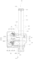
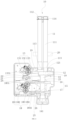
- the dispensing assembly 10 includes a storage tube 11 and a pushing portion 12.
- a storage channel 111 is defined in the storage tube 11, and is configured to store a plurality of detergent tabs therein.
- the pushing portion 12 is movably arranged relative to the storage tube 11, and is movable between a third position and a fourth position.
- the pushing portion 12 is configured to prevent the detergent tabs from falling out of the storage channel 111when in the third position, and to enable at least one detergent tab to fall out of the storage channel 111 when in the fourth position.
- the storage tube 11 is capable of storing the plurality of detergent tabs therein, and the detergent tabs are dispensed through the movement of the pushing portion 12. Therefore, the number of times the detergent tabs are added to the dispensing device 10 by a user can be reduced, which provides convenience for the user. Thus, it is possible for the user to conveniently use the dispensing device 10, and user experience is improved.
- the user may store the plurality of detergent tabs into the storage channel 111 of the storage tube 11, and then controls the pushing portion 12 to move between the third position and the fourth position, to realize the dispensing of the detergent tabs.
- the user uses the dispensing device 10 each time, there is no need for the user to first place the detergent tabs into the dispensing device 10, which can reduce the number of times the detergent tabs are added into the dispensing device 10 by the user, and convenience can be provided for the user.
- the storage tube 11 may be made of a plastic material.
- the plastic material has characteristics such as economical price, easy availability, and easy processing. Thus, manufacturing cost of the storage tube 11 can be reduced, and mass production of the storage tube 11 is facilitated, which in turn facilitates mass production of the dispensing device 10. In addition, in this way, it is possible to reduce an overall weight of the dispensing device 10 to enable the user to conveniently use the dispensing device 10, which improves the user experience.
- the storage tube 11 may also be made of other materials.
- a specific material of the storage tube 11 may be selected as desired.
- the storage tube 11 may also be made of a material such as stainless steel, iron, or the like, and the specific material of the storage tube 11 is not limited herein.
- the detergent tab may be circular, rectangular, polygonal, etc., and a specific shape of the detergent tab may be selected as desired, which is not limited herein.
- the storage tube 11 has a feeding inlet 112 and a discharging outlet 113. Both the feeding inlet 112 and the discharging outlet 113 are in communication with the storage channel 111.
- the pushing portion 12 is located at the discharging outlet 113. In this way, it is possible to control the falling of the detergent tab when the pushing portion 12 moves between the third position and the fourth position, which has a simple structure and is easy to be implemented.
- a cover plate 114 may be hinged at the feeding inlet 112.
- the cover plate 114 is configured to open or close the feeding inlet 112 through rotation. Therefore, the feeding inlet 112 can be opened and closed through rotating the cover plate 114 by the user, which is convenient and quick.
- the feeding inlet 112 may be also opened or closed by the cover plate 114 in other manners.
- the cover plate 114 may be movably arranged at the feeding inlet 112. In this case, the feeding inlet 112 may be opened or closed during the movement of the cover plate 114. Selection may be made as desired, which is not limited herein.
- the cover plate 114 may be provided with a sealing ring (not shown). In this way, when the feeding inlet 112 is closed by the cover plate 114, sealing effect of the storage channel 111 is better. Thus, it is possible to prevent external air from entering the storage channel 111, which may pollute the detergent tabs in the storage channel 111. Thus, storage of the detergent tabs can be facilitated.
- the storage channel 111 has an elongated shape to allow the plurality of detergent tabs to be arranged sequentially.
- the storage channel 111 may allow the plurality of detergent tabs to be sequentially arranged from top to bottom.
- the detergent tabs it is possible for the detergent tabs to be easily arranged sequentially. Therefore, more detergent tabs may be stored in the storage channel 111.
- the storage channel 111 of the elongated shape is also beneficial for the falling of the detergent tab under gravity to prevent the detergent tabs from being blocked in the storage channel 111.
- a plurality of storage channels 111 is provided and arranged in parallel.
- the pushing portion 12 When the pushing portion 12 is located in the fourth position, at least one of the detergent tabs in one corresponding storage channel 111 falls out of the storage channel 111.
- the plurality of storage channels 111 is arranged in parallel. In a further embodiment, the plurality of storage channels 111 is arranged in parallel in a length direction of the dispensing device 10. In this way, the falling of the detergent tab can be easily controlled when the pushing portion 12 moves, and a thickness of the dispensing device 10 can be reduced. Thus, light and thin design of the dispensing device 10 is facilitated.
- one storage tube 11 is provided, and the plurality of storage channels 111 is formed in the storage tube 11.
- a plurality of storage tubes 11 may be provided, and one storage channel 111 is formed in each of the plurality of storage tubes 11.
- the number of storage tubes may be set as desired, which is not limited herein.
- the pushing portion 12 is configured to be movable between the third position and the fourth position to enable the detergent tabs in the plurality of storage channels 111 to alternately fall out of the storage channel 111.
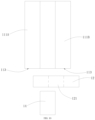
- the storage channel 111 includes a storage channel 111A and a storage channel 111B that are arranged in parallel.
- the pushing portion 12 is controlled to be positioned in a fourth position of the storage channel 111A.
- a detergent tab in the storage channel 111A falls out of the storage channel 111A as illustrated by an arrow in FIG. 7 .
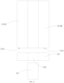
- the pushing portion 12 is controlled to be positioned in a fourth position of the storage channel 111B.
- a detergent tab in the storage channel 111B falls out of the storage channel 111B as illustrated by an arrow in FIG. 8 .
- the pushing portion 12 is controlled again to be positioned in the fourth position of the storage channel 111A.
- the detergent tab in the storage channel 111A falls out of the storage channel 111A.
- the pushing portion 12 is controlled again to be positioned in the fourth position of the storage channel 111B.
- the detergent tab in the storage channel 111B falls out of the storage channel 111B. The above operations are repeated, until the detergent tabs in the storage channel 111A and the storage channel 111B are used up.
- the dispensing device 10 may also perform the dispensing operation in other manners.
- the storage channel 111 includes a storage channel 111A and a storage channel 111B that are arranged in parallel. Three detergent tabs are stored in each of the storage channel 111A and the storage channel 111B.
- the pushing portion 12 in a first dispensing process, the pushing portion 12 is controlled to be positioned in the fourth position of the storage channel 111A. In this case, the detergent tab in the storage channel 111A falls out of the storage channel 111A.
- the pushing portion 12 is controlled again to be positioned in the fourth position of the storage channel 111A.
- the detergent tab in the storage channel 111A falls out of the storage channel 111A.
- the pushing portion 12 is controlled again to be positioned in the fourth position of the storage channel 111A.
- the detergent tab in the storage channel 111A falls out of the storage channel 111A.
- the detergent tabs in the storage channel 111A are used up.
- the pushing portion 12 in a fourth dispensing process, is controlled to be positioned in the fourth position of the storage channel 111B. In this case, the detergent tab in the storage channel 111B falls out of the storage channel 111B.
- the pushing portion 12 in a fifth dispensing process, is controlled again to be positioned in the fourth position of the storage channel 111B. In this case, the detergent tab in the storage channel 111B falls out of the storage channel 111B.
- the pushing portion 12 in a sixth dispensing process, is controlled again to be positioned in the fourth position of the storage channel 111B. In this case, the detergent tab in the storage channel 111B falls out of the storage channel 111B. At this time, the detergent tabs in the storage channel 111B are used up.
- the dispensing device 10 includes a transmission assembly 13 connected to the pushing portion 12.
- the transmission assembly 13 is configured to drive the pushing portion 12 to move between the third position and the fourth position.
- the transmission assembly 13 includes a first drive motor 131, a first transmission component 132, and a second push rod 133.
- the first drive motor 131 is configured to drive the first transmission component 132 to rotate.
- the second push rod 133 is connected to the pushing portion 12.
- the second push rod 133 is driven by the first transmission component 132 to move, to enable the pushing portion 12 to move between the third position and the fourth position.
- the first drive motor 131 is capable of driving the first transmission component 132 to rotate, and with the rotation of the first transmission component 132, the second push rod 133 is driven to move. Since the second push rod 133 is connected to the pushing portion 12, with the movement of the second push rod 133, the pushing portion 12 can be driven to move, to enable the pushing portion 12 to move between the third position and the fourth position, which has the simple structure and is easy to be implemented.
- the transmission assembly 13 may also have other structures.
- the transmission assembly 13 includes a spring and a pulling rope.
- One end of the spring is connected to the pushing portion 12, and another end of the spring is fixed to an inner wall of the dispensing device 10.
- One end of the pulling rope is connected to an end of the pushing portion 12 away from the spring, and another end of the pulling rope is exposed from the dispensing device 10.
- pulling the rope by the user may provide a pulling force in a first direction to pull the pushing portion 12, enabling the pushing portion 12 to move in the first direction.
- the spring is deformed.
- the spring may provide a pulling force in a second direction to pull the pushing portion 12, enabling the pushing portion 12 to move in the second direction.
- the first direction is opposite to the second direction.
- the pushing portion 12 when the pulling force in the first direction provided by the user is greater than the pulling force in the second direction, the pushing portion 12 can move in the first direction, and when the pulling force in the first direction provided by the user is smaller than the pulling force in the second direction, the pushing portion 12 can move in the second direction. That is, the movement of the pushing portion 12 in the first direction or the second direction can be realized through using the rope and the spring by the user, which has the simple structure and is easy to be implemented.
- the transmission assembly 13 may also have a hydraulic structure, an oil-hydraulic structure, or the like, and a specific type of the transmission assembly13 may be selected as desired, which is not limited herein.
- a first tooth portion 1331 is disposed on a side of the second push rod 133 facing towards the first transmission component 132.
- the first tooth portion 1331 is engaged with the first transmission component 132.
- the second push rod 133 can be driven to move, to further realized the movement of the pushing portion 12.
- the first transmission component 132 may include one, two, three or more gears.
- the number of gears may be selected in detail as desired, which is not limited herein. It should be noted that, when the first transmission component 132 includes a plurality of gears, the plurality of gears may be engaged with each other.
- the pushing portion 12 is formed with a through opening 121penetrating the pushing portion 12.
- the through opening 121 is in communication with the storage channel 111. Therefore, the detergent tabs in the storage channel 111 can fall into the through opening 121 and out of the storage channel 111.
- the through opening 121 is in communication with the storage channel 111. That is, only when the pushing portion 12 moves from the third position to the fourth position, the detergent tabs in the storage channel 111 can fall into the through opening 121 and out of the storage channel 111. Therefore, it is possible to avoid incorrect falling of the detergent tabs in the storage channel 111, which further facilitates the operation of the dispensing device 10.
- the through opening 121 may be circular, rectangular, triangular, or other polygons, and a specific shape of the through opening 121 may be set as desired, which is not limited herein.
- the through opening 121 has a greater size than the detergent tab, which facilitates the movement of the detergent tab in the through opening 121.
- the detergent tab it is possible to prevent the detergent tab from being stuck in the through opening 121, which may affect normal operation of the dispensing device 10.
- the dispensing device 10 includes a plurality of abutting portions 19.
- the pushing portion 12 When the pushing portion 12 is located in the fourth position, one side of the through opening 121 facing away from the storage channel 111 is at least partially closed by the abutting portion 19. Therefore, it is possible to prevent the detergent tab in the through opening 121 from directly falling from the through opening 121 when the pushing portion 12 is positioned in the fourth position, which is beneficial to control the dispensing of the detergent tab.
- one, two, three or more through openings 121 may be provided, and the specific number of through openings 121 may be set as desired, which is not limited herein.
- the dispensing device 10 includes a feeding channel 14 When the pushing portion 12 is located in the fifth position, the detergent tab in the storage channel 111 passes through the through opening 121 and falls into the feeding channel 14.
- the arrangement of the feeding channel 14 enables the detergent tabs to fall into a predetermined position, which has the simple structure and is easy to be implemented.
- one feeding channels 14 is provided.
- a plurality of the feeding channels 14 may be provided, and a specific number of the feeding channels 14 may be selected as desired, which is not limited herein.
- the feeding channel 14 has a greater size than the detergent tab, which facilitates a movement of the detergent tab in the feeding channel 14. Therefore, it is possible to prevent the detergent tab from being stuck in the feeding channel 14, which may affect the normal operation of the dispensing device 10.
- the feeding channel 14 is located on a side of the pushing portion 12 facing away from the storage channel 111.
- the feeding channel 14 has a feed opening 141.
- the detergent tab in the feeding channel 14 falls out of the feeding channel 14 through the feed opening 141.
- the storage channel 111 includes the storage channel 111A and the storage channel 111B arranged in parallel.
- the pushing portion 12 includes one through opening 121.
- One feeding channel 14 is provided and positioned in the middle of the storage channel 111A and the storage channel 111B.
- the through opening 121 is staggered with a discharging outlet 113 of the storage channel 111A and a discharging outlet 113 of the storage channel 111B.
- the through opening 121 is also staggered with the feeding channel 14. That is, in this case, the detergent tabs in the storage channel 111A and the storage channel 111B cannot fall into the through opening 121, and the detergent tabs in the through opening 121 cannot fall into the feeding channel 14, either.
- the through opening 121 is in communication with one of the discharging outlet 113 of the storage channel 111A and the discharging outlet 113 of the storage channel 111B. Another side of the through opening 121 is closed by the abutting portion 19. That is, in this case, the detergent tab in the storage channel 111A or the storage channel 111B can fall into the through opening 121, and is abutted against the abutting portion 19. Therefore, the detergent tab in the through opening 121 cannot fall into the feeding channel 14.
- the through opening 121 is staggered with the discharging outlet 113 of the storage channel 111A and the discharging outlet 113 of the storage channel 111B, and the through opening 121 is in communication with and the feeding channel 14. That is, in this case, the detergent tab in the through opening 121 can fall into the feeding channel 14.
- the falling of the detergent tab in the storage channel 111 can be controlled by allowing the pushing portion 12 to move among the third position, the fourth position, and the fifth position, which has the simple structure and is easy to be implemented.
- a movable assembly 15 is disposed in the feeding channel 14.
- the movable assembly 15 is movable to block or unblock the feeding channel 14.
- the movable assembly 15 is configured to enable the detergent tabs in the feeding channel 14 to fall out of the feeding channel 14 when the feeding channel 14 is unblocked.
- the feeding channel 14 is blocked or unblocked through the arrangement of the movable assembly 15. Therefore, the movement of the detergent tab in the feeding channel 14 can be conveniently controlled to prevent a solid detergent falling into the feeding channel 14 through the through opening 121 from directly falling out of the feeding channel 14.
- moisture or other foreign materials outside the feeding channel 14 may be blocked by the movable assembly 15 when entering the feeding channel.
- the movable assembly 15 has advantages such as moisture-proof, dustproof, and movement controlling of the detergent tab.
- the movable assembly 15 is plate-shaped.
- a plurality of sliding channels is formed in the feeding channel 14, and is in communication with the feeding channel 14.
- the movable assembly 15 is configured to move into the feeding channel 14 through the plurality of sliding channels to block the feeding channel 14, or move outwards from the feeding channel 14 through the plurality of sliding channels to unblock the feeding channel 14.
- the arrangement of the plurality of sliding channels may guide the movable assembly 15 to avoid an inaccurate movement of the movable assembly 15, which may cause the feeding channel 14 not to be blocked by the movable assembly 15.
- the movable assembly 15 moves along the sliding channels to block or unblock the feeding channel 14, which has the simple structure and is easy to be implemented.
- the movable assembly 15 includes a first movable block 16 and a second movable block 17.
- the first movable block 16 and the second movable block 17 are disposed in the feeding channel 14 and spaced apart from each other.
- the first movable block 16 is located between the second movable block 17 and the pushing portion 12.
- the second movable block 17 can block or unblock the feeding channel 14.
- the second movable block 17 can block or unblock the feeding channel 14.
- the movement of the detergent tab in the feeding channel 14 can be controlled by the first movable block 16 and the second movable block 17.
- the control effect is better.
- the second movable block 17 can block or unblock the feeding channel 14.
- the first movable block 16 or the second movable block 17 is in operation, one of the first movable block 16 or the second movable block 17 can block the feeding channel 14. Therefore, in a process of dispensing the detergent tab, it is possible to prevent external air from entering the feeding channel 14 into the storage channel 111 through the feeding channel 14. Thus, it is beneficial for protecting the detergent tabs in the storage channel 111.
- the detergent tab is located on the first movable block 16.
- the second movable block 17 can block or unblock the feeding channel 14. In this way, it is possible to prevent the external air from entering the storage channel 111 through the first movable block 16.
- the detergent tab on the first movable block 16 falls onto the second movable block 17. In this case, the second movable block 17 can block the feeding channel 14.
- cooperation between the first movable block 16 and the second movable block 17 can prevent the external air from entering the storage channel 111 to further facilitate the storage of the detergent tab in the storage channel 111.
- the dispensing device 10 includes a drive assembly 18 connected to the first movable block 16 and the second movable block 17.
- the drive assembly 18 is configured to drive the first movable block 16 and the second movable block 17 to move.
- the first movable block 16 and the second movable block 17 is driven to move by one drive assembly 18. Therefore, it is not necessary to provide two drive assemblies 18 to drive the first movable block 16 and the second movable block 17 to move, respectively. Thus, a manufacturing cost of the dispensing device 10 can be reduced, which facilitates mass production of the dispensing device 10.
- two drive assemblies 18 may also be provided to drive the first movable block 16 and the second movable block 17 to move, respectively, which may be designed as desired and is not limited herein.
- the drive assembly 18 includes a second drive motor 181, a second transmission component 182, a first push rod 183, and a third push rod 184.
- the second drive motor 181 is configured to drive the second transmission component 182 to rotate.
- the first push rod 183 is connected to the first movable block 16.
- the third push rod 184 is connected to the second movable block 17.
- the first push rod 183 and the third push rod 184 is driven by the second transmission component 182 to move, to drive the first movable block 16 and the second movable block 17 to move.
- the second drive motor 181 is capable of driving the second transmission component 182 to rotate. With the rotation of the second transmission component 182, the first push rod 183 and the third push rod 184 are driven to move. Since the first push rod 183 is connected to the first movable block 16, and the third push rod 184 is connected to the second movable block 17, with the movements of the first push rod 183 and the third push rod 184, the first movable block 16 and the second movable block 17 can be driven to move, which in turn enables the first movable block 16 and the second movable block 17 to block or unblock the feeding channel 14, which has the simple structure and is easy to be implemented.
- the movements of the first movable block 16 and the second movable block 17 may be implemented by one drive assembly 18. That is, in the embodiments of the present disclosure, the movements of the first movable block 16 and the second movable block 17 are driven in a linkage manner. Of course, in other embodiments, the movements of the first movable block 16 and the second movable block 17 may also be driven in a separate control manner. For example, two transmission assemblies 13 may be provided to respectively drive the movements of the first movable block 16 and the second movable block 17. The specific arrangement may be designed as desired, which is not limited herein.
- a second tooth portion 1831 is disposed on a side of the first push rod 183 facing towards the second transmission component 182.
- a third tooth portion 1841 is provided on a side of the third push rod 184 facing towards the second transmission component 182. The second tooth portion 1831 and the third tooth portion 1841 are engaged with the second transmission component 182.
- the first push rod 183 and the third push rod 184 can be driven to move, to further realize the movements of the first movable block 16 and the second movable block 17.
- the second transmission component 182 may include a first driving wheel 1821, a first driven wheel 1822, a second driven wheel 1823, and a third driven wheel 1824.
- the first driving wheel 1821 is engaged with the second drive motor 181.
- the first driving wheel 1821 is engaged with the first driven wheel 1822.
- the second driven wheel 1823 and the third driven wheel 1824 are engaged with the first driven wheel 1822.
- the second tooth portion 1831 is engaged with the second driven wheel 1823.
- the third tooth portion 1841 is engaged with the third driven wheel 1824.
- the second tooth portion 1831 and the third tooth portion 1841 are opposite to each other.
- the second drive motor 181 can drive the first driving wheel 1821 to rotate.
- the first driving wheel 1821 rotates, the first driving wheel 1821 can drive the first driven wheel 1822 to rotate. Since the second driven wheel 1823 and the third driven wheel 1824 are engaged with the first driven wheel 1822, when the first driven wheel 1822 rotates, the first driven wheel 1822 can drive the second driven wheel 1823 and the third driven wheel 1824 to rotate in opposite directions.
- the first push rod 183 and the third push rod 184 can be driven to move in opposite directions by the second tooth portion 1831 and the third tooth portion 1841, to further allow the first movable block 16 and the second movable block 17 to move in opposite directions. That is, linkage between the first movable block 16 and the second movable block 17 may be implemented by one second transmission component 182, which has the simple structure and is easy to be implemented.
- the second transmission component 182 may also include a plurality of driving wheels or a plurality of driven wheels.
- the second transmission component 182 may include two, three, four, five, or more driving wheels, and may include four, five, six, or more driven wheels.
- the specific number of the driving wheel and the driven wheel may be designed as desired as long as the first push rod 183 and the third push rod 184 are allowed to move in different directions, and the specific number of the driving wheels and the driven wheels is not limited herein.
- the first movable block 16 and the second movable block 17 each are provided with a sealing structure (not shown).
- the sealing structure is configured to seal the feeding channel 14 at ends of the first movable block 16 and the second movable block 17 when the first movable block 16 and the second movable block 17 allows the feeding channel 14 to be blocked or unblocked.
- the feeding channel 14 at the ends of the first movable block 16 and the second movable block 17 can be sealed by the arrangement of the sealing structure, when he first movable block 16 and the second movable block 17 block or unblock the feeding channel 14.
- the sealing structure may be at least one of rubber and an O-shaped ring.
- the sealing structure not only includes the above two structures, and in other embodiments, the sealing structure may also include other structures, and the specific structure may be designed as desired, which is not limited herein.
- inventions of the present disclosure provide a door body assembly 100.
- the door body assembly 100 includes a door body 101 and the dispensing device 10 according to any one of the above embodiments.
- the dispensing device 10 is disposed on the door body 101.
- the storage tube 11 is configured to store the plurality of detergent tabs, and the detergent tabs are then dispensed through the movement of the pushing portion 12. Therefore, the number of times the detergent tabs are added into the dispensing device 10 by the user can be reduced, which provides convenience for the user. Thus, it is possible for the user to conveniently use the dispensing device 10, and user experience is improved.
- the door body 101 may be a door body 101 of a household appliance 1000.
- the door body 101 is configured to open or close a cavity 1001 of the household appliance 1000.
- the dispensing device 10 is configured to dispense the detergent tabs into the cavity 1001 of the household appliance 1000. Therefore, the dispensing device 10 does not need to be additionally mounted, which is convenient and quick.
- the dispensing device 10 is detachably connected to the door body 101. In this way, when the dispensing device 10 is damaged, it is convenient for the user to maintain or replace the dispensing device 10.
- the dispensing device 10 may be screwed onto the door body 101.
- the dispensing device 10 may be connected to the door body 101 in other manners, and the specific connection may be selected as desired, which is not limited herein.
- the household appliance 1000 includes a cavity 1001 and the door body assembly 100 as described above.
- An accommodation space 1002 is formed in the cavity 1001.
- the door body assembly 100 is rotatably connected to the cavity 1001.
- the door body assembly 100 is configured to open or close the accommodation space 1002 with the rotation of the door body assembly 100.
- the dispensing device 10 is located within the accommodation space 1002.
- the storage tube 11 is configured to store the plurality of detergent tabs, and the detergent tabs are then dispensed through the movement of the pushing portion 12. Therefore, the number of times the detergent tabs are added into the dispensing device 10 by the user can be reduced, which provides convenience for the user. Thus, it is possible for the user to conveniently use the dispensing device 10, and user experience is improved.
- the household appliance 1000 may be an electric appliance such as a dishwasher and a washing machine, in which the detergent tabs are used.
- the household appliance 1000 may also be other electrical appliances, and the specific type of the household appliance 1000 may be provided as desired, which is not limited herein.
- the door body assembly 100 is hinged to the household appliance 1000.
- the door body assembly 100 may be connected to the household appliance 1000 in other manners such as a sliding connection or a snapping connection, and the specific connection manner may be selected as desired, which is not limited herein, as long as the cavity 1001 of the household appliance 1000 is openable or closable by the door body assembly 100.
- the present invention provides a control method applied in a dispensing device 10.
- the dispensing device 10 includes a feeding tube 23, a first movable block 16, and a second movable block 17.
- the first movable block 16 and the second movable block 17 are disposed in the feeding tube 23 and spaced apart from each other.
- the feeding tube 23 has a feeding channel 14 defined therein.
- the first movable block 16 and the second movable block 17 are configured to block or unblock the feeding channel 14.
- the control method includes actions at blocks S10 and S20.
- the first movable block 16 is controlled to move to unblock the feeding channel 14, and the second movable block 17 is kept blocking the feeding channel 14, to enable a detergent tab on the first movable block 16 to fall between the first movable block 16 and the second movable block 17.
- the second movable block 17 is controlled to unblock the feeding channel 14, and the first movable block 16 is kept blocking the feeding channel 14, to enable a detergent tab between the first movable block 16 and the second movable block 17 to fall out of the feeding channel 14.
- the second movable block 17 is kept in the state to block the feeding channel 14.
- the second movable block 17 is kept in the state to block the feeding channel 14. That is, one of the first movable block 16 and the second movable block 17 allows the feeding channel 14 to be unblocked, and the other one of the first movable block 16 and the second movable block 17 is to block the feeding channel 14. In this way, the steam cannot enter the feeding channel 14, which in turn prevents the steam from affecting the detergent tabs in the feeding channel 14, to facilitate the operation of the dispensing device 10.
- the arrangement of the feeding channel 14 enables the detergent tab to fall to a predetermined position, which facilitates the control on the falling position of the detergent tab, and it is beneficial for using of the dispensing device 10.
- the decomposed detergent tab may be adhered on the feeding channel 14. In this case, an overall weight of the detergent tab may be reduced, which is not beneficial for using of the detergent tab.
- one of the first movable block 16 and the second movable block 17 allows the feeding channel 14 to be unblocked, and the other one of the first movable block 16 and the second movable block 17 is to block the feeding channel 14. In this way, the steam cannot enter the feeding channel 14, which in turn prevents the steam from affecting the detergent tabs in the feeding channel 14, to facilitate the operation of the dispensing device 10.
- the dispensing device 10 includes a drive assembly 18.
- the drive assembly 18 is connected to the first movable block 16 and the second movable block 17.
- the drive assembly 18 is configured to drive the first movable block 16 and the second movable block to move 17 to move.
- the control method includes actions at blocks S30 and S40.
- the drive assembly 18 is controlled to operate to drive the first movable block 16 to move in a direction to unblock the feeding channel 14 and to drive the second movable block 17 to move to block the feeding channel 14.
- the drive assembly 18 is controlled to operate to drive the first movable block 16 to move in a direction to block the feeding channel 14 and to drive the second movable block 17 to move to keep the feeding channel 14 being unblocked.
- a movement direction of the first movable block 16 is opposite to a movement direction of the second movable block 17.
- the second movable block 17 can move in the direction to block the feeding channel 14; or when the first movable block 16 moves in the direction to block the feeding channel 14, the second movable block 17 can move in the direction to unblock the feeding channel 14. Therefore, one of the first movable block 16 and the second movable block 17 allows the feeding channel 14 to be unblocked, and the other one of the first movable block 16 and the second movable block 17 is to block the feeding channel 14. In this way, the steam cannot enter the feeding channel 14, which in turn prevents the steam from affecting the detergent tab in the feeding channel 14, to facilitate the operation of the dispensing device 10.
- first movable block 16 and the second movable block 17 may move first in a same direction, and then move in the opposite direction, and vice versa, and the specific movement directions of the first movable block 16 and the second movable block 17 may be designed as desired, which is not limited herein, as long as one of the first movable block 16 and the second movable block 17 allows the feeding channel 14 to be unblocked, and the other one of the first movable block 16 and the second movable block 17 is to block the feeding channel 14.
- the dispensing device 10 includes a first push rod 183 connected tc the first movable block 16, and a first position detector 24 disposed on a side of the first push rod 183.
- the first push rod 183 is connected to the drive assembly 18.
- the control method includes actions at blocks S50 to S70.
- the drive assembly 18 is controlled to operate to drive the first push rod 183 to move in a direction approaching the first position detector 24.
- the first position detector 24 may be a contact resistance detector.
- the contact resistance detector is disposed in the first position.
- a resistance of the contact resistance detector changes.
- an output current of the contact resistance detector also changes.
- the resistance of the contact resistance detector does not change. That is, the output current of the contact resistance detector does not change. In this way, it is determined that the first push rod 183 is not located in the first position at this time, and the feeding channel 14 is blocked by the first movable block 16.
- the first position detector 24 may also be of other types, and the specific type of the first position detector 24 may be designed as desired.
- the first position detector 24 may also be a range sensor 20.
- the range sensor 20 is configured to detect a distance between the range sensor 20 and the first push rod 183.
- a specific position of the first push rod 183 is determined by a specific value of the distance between the range sensor 20 and the first push rod 183.
- the specific value of the distance between the range sensor 20 and the first push rod 183 may be 0.1c fourth position, 0.2c fourth position, 0.3c fourth position, or the like.
- the specific value of the distance between the range sensor 20 and the first push rod 183 may be set as desired, which is not limited herein.
- the specific value of the distance between the range sensor 20 and the first push rod 183 may be adjusted based on a position of the range sensor 20.
- control method further includes: determining, in response to the determination that the first push rod 183 is not in contact with the first position detector 24, that the first push rod 183 is not located in the first position.
- the first push rod 183 may be located at any position between the first position and the second position, which is not limited herein.
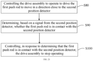
- the dispensing device 10 includes the first push rod 183 connected to the first movable block 16, and a second position detector 25 disposed on a side of the first push rod 183.
- the first push rod 183 is connected to the drive assembly 18. When the first push rod 183 is located in a second position, the feeding channel 14 is blocked by the first movable block 16.
- the control method includes actions at blocks S80 to S100.
- the drive assembly 18 is controlled to operate to drive the first push rod 183 to move in a direction approaching the second position detector 25.
- an operation principle of the second position detector 25 is same as that of the first position detector 24, and thus the description of the second position detector 25 may refer to that of the first position detector 24, which will be omitted herein.
- the specific position in which the first push rod 183 is located may be clearly obtained through the first position detector 24 and the second position detector 25, which facilitates control efficiency of the dispensing device 10 and further improves operation efficiency of the dispensing device 10.
- the dispensing device 10 includes a detection assembly 26 located between the first movable block 16 and the second movable block 17.
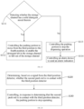
- the control method further includes, prior to controlling the second movable block 17 to move to allow the feeding channel 14 to be unblocked, actions at blocks S12 and S12.
- the drive assembly 18 in response to presence of the detergent tab between the first movable block 16 and the second movable block 17, the drive assembly 18 is controlled to operate to drive the second movable block 17 to move in the direction to unblock the feeding channel 14, to enable the detergent tab between the first movable block 16 and the second movable block 17 to fall out of the feeding channel 14.
- the drive assembly 18 in response to detecting, by the detection assembly 26, the presence of the detergent tab between the first movable block 16 and the second movable block 17, the drive assembly 18 can operate to drive the second movable block 17 to move in the direction to unblock the feeding channel 14, to enable the detergent tab between the first movable block 16 and the second movable block 17 to fall out of the feeding channel 14.
- the drive assembly 18 does not operate. In this way, it is possible to avoid improper operation of the drive assembly 18, which is beneficial for the normal operation of the dispensing device 10.
- the detection assembly 26 may be a photoelectric reflection sensor.
- the photoelectric reflection sensor includes an emitter and a receiver.
- the emitter and the receiver are arranged at a same side of the feeding channel 14, respectively.
- the emitter is configured to emit a light.
- the light may be reflected by the detergent tab and then received by the receiver.
- the receiver is configured to determine, based on a light receiving time, whether the feeding channel 14 has the detergent tab stored therein. When the feeding channel 14 has the detergent tab stored therein, the light emitted from the emitter may be reflected by a surface of the detergent tab, and then the reflected light may be received by the receiver.
- the light emitted from the emitter may be reflected by a surface of the feeding channel 14, and then the reflected light may be received by the receiver. Since the detergent tab may occupy a space of the feeding channel 14, when the feeding channel 14 has the detergent tab stored therein, a time in which the light is received by the receiver is relatively short. When he feeding channel 14 has no detergent tab stored therein, the time in which the light is received by the receiver is relatively long. It may be determined, by calculating the time in which the light is received by the receiver, whether the feeding channel 14 has the detergent tab stored therein.
- the detection assembly 26 may be an infrared sensor.
- the infrared sensor includes an emitter and a receiver.
- the emitter and the receiver are located at two opposite sides in the feeding channel 14.
- the emitter is configured to emit an infrared light to the receiver, and the infrared light emitted from the emitter is received by the receiver.
- the infrared light emitted from the emitter can be always received by receiver.
- the infrared light may be blocked by the detergent tab to cause the receiver not to receive the infrared light emitted from the emitter. That is, it may be determined, by determining whether the infrared light emitted from the emitter can be received by the receiver, whether the feeding channel 14 has the detergent tab stored therein.
- the detection assembly 26 not only includes the two detection assemblies as described above, and the specific type of the detection assembly 26 may be set as desired.
- the detection assembly 26 may also be a light proximity sensor, an optocoupler sensor, or the like.
- the specific type of the detection assembly 26 is not limited herein.
- the dispensing device 10 includes a pushing portion 12, and a storage tube 11 having a storage channel 111.
- the storage channel 111 is configured to store the detergent tabs therein.
- the control method further includes, prior to controlling the first movable block 16 to move: controlling the pushing portion 12 to move to enable the detergent tabs in the storage channel 111 to fall into the feeding channel 14.
- the pushing portion 12 is located between the feeding channel 14 and the storage channel 111, and is moveable between a third position and a fourth position.
- the operation of controlling the pushing portion 12 to move to enable the detergent tabs in the storage channel 111 to fall into the feeding channel 14 includes actions at blocks S111 and S112.
- the pushing portion 12 is controlled to move from the third position to the fourth position, to enable the detergent tab in the storage channel 111 to fall out of the storage channel 111.
- the storage channel 111 is configured to store the detergent tab therein.
- the dispensing device 10 may automatically perform dispensing operation. That is, the user may store the detergent tabs into the storage channel 111, which can reduce the number of times the detergent tabs are added into the dispensing device 10 by the user, and convenience can be provided for the user. Thus, it is possible for the user to conveniently use the dispensing device 10, and user experience is improved.
- the dispensing device 10 further includes an alarm device.
- the control method further includes, in response to detecting that the storage channel 111 has no detergent tab stored therein, actions at blocks S113 and S113.
- the pushing portion 12 is controlled to stop the dispensing operation.
- the alarm device is controlled to send an alarm indication.
- the pushing portion 12 In response to detecting that the storage channel 111 has no detergent tab stored therein, the pushing portion 12 is controlled to stop the dispensing operation, and the alarm indication is sent by the alarm device to inform the user that there is no detergent tab stored in the storage channel 111. In this way, the detergent tabs may be added into the storage channel 111 by the user after the alarm indication is received, to enable the dispensing device 10 to operate normally.
- the alarm indication may be a voice indication, a lighting indication, or a combination thereof.
- the alarm device may be a voice player.
- the voice player In response to detecting that the storage channel 111 has no detergent tab stored therein, the voice player is controlled to operate to send the voice indication to inform the user that there is no detergent tab stored in the storage channel 111.
- the alarm device may be an alarm light. In response to detecting that the storage channel 111 has no detergent tab stored therein, the alarm light is controlled to operate to send the light indication to inform the user that there is no detergent tab stored in the storage channel 111.
- the alarm device may also be other devices, and the specific type of the alarm device may be selected as desired, which is not limited herein, as long as the alarm device can inform the user whether the storage tube 11 has the detergent tab stored therein.
- a function of the sensor 20 is the same as that of the detection assembly 26. Description of an operating principle of the sensor 20 may refer to that of the detection assembly 26, which will be omitted herein. That is, one sensor 20 as described above is disposed in the storage channel 111 to perform a detection operation on the storage channel 111. Of course, in other embodiments, other methods may be used to detect whether the storage channel 111 has the detergent tab stored therein, and may be selected as desired, which is not limited herein.
- the dispensing device 10 includes a second push rod 133 connected to the pushing portion 12, and a third position detector 21 disposed on a side of the second push rod 133.
- the control method includes actions at blocks S120 and S130.
- the dispensing device 10 includes a transmission assembly 13 connected to a second push rod 133, and a fourth position detector 22 disposed on a side of the second push rod 133.
- the operation at block S112 includes actions at blocks S1121 and S1122.
- the transmission assembly 13 is controlled to operate to drive the second push rod 133 to move, to allow the pushing portion 12 to move from the third position to the fourth position.
- the transmission assembly 13 in response to determining, based on a signal from the fourth position detector 22, that the pushing portion 12 is in the fourth position, the transmission assembly 13 is controlled to stop operating, to maintain the pushing portion 12 in the fourth position.
- the position where the current pushing portion 12 is located can be efficiently and accurately determined.
- the detection accuracy can be improved, and it is beneficial for the normal operation of the dispensing device 10.
- the operation of the pushing portion 12 is stopped, which facilitates the falling of the detergent tabs of the dispensing device 10.
- an operation principle of the third position detector 21 and the fourth position detector 22 is same as that of the first position detector 24, and the specific description of the third position detector 21 and the fourth position detector 22 may refer to that of the first position detector 24, which will be omitted herein.
- the dispensing device 10 includes a controller, a feeding tube 23, a first movable block 16, and a second movable block 17.
- the first movable block 16 and the second movable block 17 are arranged in the feeding tube 23 and spaced apart from each other.
- the feeding tube 23 is formed with a feeding channel 14.
- the first movable block 16 and the second movable block 17 are configured to unblock or block the feeding channel 14.
- the controller is configured to: control the first movable block 16 to move to unblock the feeding channel 14, and keep the second movable block 17 blocking the feeding channel 14, to enable a detergent tab on the first movable block 16 to fall between the first movable block 16 and the second movable block 17; and control the second movable block 17 to move to unblock the feeding channel 14, and keep the first movable block 16 blocking the feeding channel 14, to enable a detergent tab between the first movable block 16 and the second movable block 17 to fall out of the feeding channel 14.
- the second movable block 17 when the first movable block 16 allows the feeding channel 14 to be unblocked, the second movable block 17 is kept in the state to block the feeding channel 14.
- the second movable block 17 is kept in the state to unblock the feeding channel 14. That is, one of the first movable block 16 and the second movable block 17 allows the feeding channel 14 to be unblocked, and the other one of the first movable block 16 and the second movable block 17 is to block the feeding channel 14. In this way, the steam cannot enter the feeding channel 14, which in turn prevents the steam from affecting the detergent tabs in the feeding channel 14, to facilitate the operation of the dispensing device 10.
- the dispensing device 10 includes a drive assembly 18.
- the drive assembly 18 is connected to the first movable block 16 and the second movable block 17.
- the drive assembly 18 is configured to drive the first movable block 16 and the second movable block 17 to move.
- the controller is configured to: control the drive assembly 18 to operate to drive the first movable block 16 to move in a direction to unblock the feeding channel 14 and to drive the second movable block 17 to move to keep the second movable block 17 blocking the feeding channel 14; and control the drive assembly 18 to operate to drive the first movable block 16 to move in a direction to block the feeding channel 14 and to drive the second movable block 17 to move to allow the second movable block 17 to keep the feeding channel 14 being blocked.
- the dispensing device 10 includes a first push rod 183 connected to the first movable block 16, and a first position detector 24 disposed on a side of the first push rod 183.
- the first push rod 183 is connected to the drive assembly 18.
- the controller is configured to: control the drive assembly 18 to operate to drive the first push rod 183 to move in a direction approaching the first position detector 24; determine, based on a signal from the first position detector 24, whether the first push rod 183 is in contact with the first position detector 24; and control, in response to the determination that the first push rod 183 is in contact with the first position detector 24, the drive assembly 18 to stop operating.
- the drive assembly 18 can be kept in the state in which the feeding channel 14 is unblocked, which is beneficial for the falling of the detergent tabs.
- the dispensing device 10 includes the first push rod 183 connected to the first movable block 16, and a second position detector 25 disposed on a side of the first push rod 183.
- the first push rod 183 is connected to the drive assembly 18.
- the controller is configured to: control the drive assembly 18 to operate to drive the first push rod 183 to move in a direction approaching the second position detector 25; determine, based on a signal from the second position detector 25, whether the first push rod 183 is in contact with the second position detector 25; and control, in response to the determination that the first push rod 183 is in contact with the second position detector 25, the drive assembly 18 to stop operating.
- the drive assembly 18 can be kept in the state in which the feeding channel 14 is unblocked, which is beneficial for the falling of the detergent tabs.
- the dispensing device 10 includes a detection assembly 26.
- the detection assembly 26 is located between the first movable block 16 and the second movable block 17.
- the controller is configured to: detect, by the detection assembly 26, whether the detergent tab is present between the first movable block 16 and the second movable block 17; and control, in response to the presence of the detergent tab between the first movable block 16 and the second movable block 17, the drive assembly 18 to operate to drive the second movable block 17 to move in the direction to unblock the feeding channel 14, to enable the detergent tab between the first movable block 16 and the second movable block 17 to fall out of the feeding channel 14.
- the drive assembly 18 operates to drive the second movable block 17 to move in the direction to unblock the feeding channel 14, to enable the detergent tab between the first movable block 16 and the second movable block 17 to fall out of the feeding channel 14.
- the drive assembly 18 does not operate. In this way, it is possible to avoid improper operation of the drive assembly 18, which is beneficial for the normal operation of the dispensing device 10.
- the dispensing device 10 includes a pushing portion 12, and a storage tube 11 having a storage channel 111.
- the storage channel 111 is configured to store the detergent tab therein.
- the controller is configured to control the pushing portion 12 to move to enable the detergent tab in the storage channel 111 to fall into the feeding channel 14.
- the pushing portion 12 is located between the feeding channel 14 and the storage channel 111, and is moveable between a third position and a fourth position.
- the controller is configured to: detect whether the storage channel 111 has the detergent tab stored therein; and control, in response to detecting that the storage channel 111 has the detergent tab stored therein, the pushing portion 12 to move from the third position to the fourth position, to enable the detergent tab in the storage channel 111 to fall out of the storage channel 111.
- the storage channel 111 is configured to store the detergent tab.
- the dispensing device 10 can automatically perform the dispensing operation. That is, the user may store the detergent tab into the storage channel 111, which can reduce the number of times the detergent tabs are added into the dispensing device 10 by the user, and convenience can be provided for the user. Thus, it is possible for the user to conveniently use the dispensing device 10, and user experience is improved.
- the dispensing device 10 includes a second push rod 133 connected to the pushing portion 12, and a third position detector 21 disposed on a side of the second push rod 133.
- the controller is configured to: determine, based on a signal from the third position detector 21, whether the second push rod 133 is in contact with the third position detector 21; and control, in response to the determination that the second push rod 133 is in contact with the third position detector 21, the pushing portion 12 to stop operating.
- the dispensing device 10 includes a transmission assembly 13 connected to the second push rod 133, and a fourth position detector 22 disposed on a side of the second push rod 133.
- the controller is configured to: control the transmission assembly 13 to operate to drive the second push rod 133 to move, to allow the pushing portion 12 to move from the third position to the fourth position; and control, in response to a determination that the pushing portion 12 is in the fourth position based on a signal of the fourth position detector 22, the transmission assembly 13 to stop operating, to allow the pushing portion 12 to be positioned in the fourth position.
- a non-volatile computer-readable storage medium includes computer-executable instructions.
- the computer-executable instructions when executed by one or more processors, cause the processor to perform the control method according to any one of the above embodiments.
- the storage tube 11 is configured to store the plurality of detergent tabs therein, then the number of the detergent tabs in the storage tube 11 is obtained, and the number of the obtained detergent tabs is notified. In this way, the user may clearly know the number of the detergent tabs in the storage tube 11. When the detergent tabs are insufficient, the detergent tabs are added into the storage tube 11 to avoid the insufficiency of the detergent tabs to be dispensed, which is beneficial for the user to use the household appliance 1000.
- each function cell of the embodiments of the present disclosure may be integrated in one processing module, or these units may be separate physical existence, or two or more units are integrated in one processing module.
- the integrated module may be implemented in a form of hardware or software function module. When implemented in the form of software function module and is sold or used as a standalone product, the integrated module may be stored in the computer-readable storage medium.
Landscapes
- Engineering & Computer Science (AREA)
- Textile Engineering (AREA)
- Devices For Dispensing Beverages (AREA)
- Cleaning By Liquid Or Steam (AREA)
- Washing And Drying Of Tableware (AREA)
Description
- The present invention relates to a control method, a dispensing device, a household appliance.
- In the related art, a household appliance (such as a dishwasher) usually uses a device with an automatic dispensing function to dispense a cleaning consumable. For the device with the automatic dispensing function in the related art, in a process of dispensing the cleaning consumable, steam from the household appliance may easily enter an inside of the device with the automatic dispensing function. Therefore, quality of cleaning consumable in the device with the automatic dispensing function may be easily influenced, which does not facilitate an operation of the household appliance.
DE19540958A1 relates generally to a dosing device for cleaning agents in tablet.CN101744597A relates generally to a dishwashing machine that sprays cleaning water on items to be cleaned.WO2005100675A2 relates generally to a device being structured in such a way as to prevent any deterioration and/or anomalous behaviors of elements or substances contained therein and/or of parts of the device itself. - Aspects of the invention are set out in the claims.
- Additional aspects and advantages of the present disclosure will be partially set forth in the following description and partially become apparent from the following description, or they may be learned by practice of the present disclosure.
- The above-mentioned and/or additional aspects and advantages of the present disclosure will become apparent and readily understood from the following description of embodiments in conjunction with the accompanying drawings, in which:
-
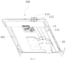
FIG. 1 is a schematic structural view of a dispensing device according to an embodiment of the present disclosure; -
FIG. 2 is a schematic plan view of a dispensing device according to an embodiment of the present disclosure; -
FIG. 3 is another schematic plan view of a dispensing device according to an embodiment of the present disclosure; -
FIG. 4 is another schematic plan view of a dispensing device according to an embodiment of the present disclosure; -
FIG. 5 is yet another schematic plan view of a dispensing device according to an embodiment of the present disclosure; -
FIG. 6 is yet another schematic plan view of a dispensing device according to an embodiment of the present disclosure; -
FIG. 7 is a schematic plan view of a storage channel and a pushing portion of a dispensing device according to an embodiment of the present disclosure; -
FIG. 8 is another schematic plan view of a storage channel and a pushing portion of a dispensing device according to an embodiment of the present disclosure; -
FIG. 9 is yet another schematic plan view of a storage channel and a pushing portion of a dispensing device according to an embodiment of the present disclosure; -
FIG. 10 is another schematic plan view of a storage channel and a pushing portion of a dispensing device according to an embodiment of the present disclosure; -
FIG. 11 is still yet another schematic plan view of a storage channel and a pushing portion of a dispensing device according to an embodiment of the present disclosure; -
FIG. 12 is a schematic enlarged view of part I inFIG. 6 ; -
FIG. 13 is a schematic structural view of a door assembly according to an embodiment of the present disclosure; -
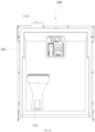
FIG. 14 is a schematic plan view of a door assembly according to an embodiment of the present disclosure; -
FIG. 15 is another schematic plan view of a door assembly according to an embodiment of the present disclosure; -
FIG. 16 is a schematic structural view of a household appliance according to an embodiment of the present disclosure; -
FIG. 17 is another schematic structural view of a household appliance according to an embodiment of the present disclosure; -
FIG. 18 is a flowchart of a control method for a dispensing device according to an embodiment of the present disclosure; -
FIG. 19 is another flowchart of a control method for a dispensing device according to an embodiment of the present disclosure; -
FIG. 20 is yet another flowchart of a control method for a dispensing device according to an embodiment of the present disclosure; -
FIG. 21 is another flowchart of a control method for a dispensing device according to an embodiment of the present disclosure; -
FIG. 22 is still yet another flowchart of a control method for a dispensing device according to an embodiment of the present disclosure; -
FIG. 23 is yet another flowchart of a control method for a dispensing device according to an embodiment of the present disclosure; -
FIG. 24 is still yet another flowchart of a control method for a dispensing device according to an embodiment of the present disclosure; and -
FIG. 25 is another flowchart of a control method for a dispensing device according to an embodiment of the present disclosure. -
Household appliance 1000,cavity 1001,accommodation space 1002,door body assembly 100,door body 101,dispensing device 10,storage tube 11,storage channel 111,feeding inlet 112,discharging outlet 113,cover plate 114, pushingportion 12, throughopening 121,transmission assembly 13,first drive motor 131,first transmission component 132,second push rod 133,first tooth portion 1331,feeding channel 14,feed opening 141,movable assembly 15, firstmovable block 16, secondmovable block 17,drive assembly 18,second drive motor 181,second transmission component 182,first driving wheel 1821, first drivenwheel 1822, second drivenwheel 1823, third drivenwheel 1824,first push rod 183,second tooth portion 1831,third push rod 184,third tooth portion 1841, abuttingportion 19,sensor 20,third position detector 21,fourth position detector 22,feeding tube 23,first position detector 24,second position detector 25, anddetection assembly 26. - Embodiments of the present disclosure will be described in detail below with reference to embodiments thereof as illustrated in the accompanying drawings, throughout which the same or similar elements, or the elements having same or similar functions, are denoted with same or similar reference numerals. The embodiments described below with reference to the accompanying drawings are illustrative merely and are intended to explain, rather than limiting, the present disclosure.
- Referring to
FIG. 1 to FIG. 3 , adispensing assembly 10 according to embodiments of the present disclosure is provided. Thedispensing assembly 10 includes astorage tube 11 and a pushingportion 12. Astorage channel 111 is defined in thestorage tube 11, and is configured to store a plurality of detergent tabs therein. The pushingportion 12 is movably arranged relative to thestorage tube 11, and is movable between a third position and a fourth position. The pushingportion 12 is configured to prevent the detergent tabs from falling out of the storage channel 111when in the third position, and to enable at least one detergent tab to fall out of thestorage channel 111 when in the fourth position. - With the
dispensing device 10 according to the embodiments of the present disclosure, thestorage tube 11 is capable of storing the plurality of detergent tabs therein, and the detergent tabs are dispensed through the movement of the pushingportion 12. Therefore, the number of times the detergent tabs are added to the dispensingdevice 10 by a user can be reduced, which provides convenience for the user. Thus, it is possible for the user to conveniently use thedispensing device 10, and user experience is improved. - In the embodiments of the present invention, the user may store the plurality of detergent tabs into the
storage channel 111 of thestorage tube 11, and then controls the pushingportion 12 to move between the third position and the fourth position, to realize the dispensing of the detergent tabs. In this way, when the user uses thedispensing device 10 each time, there is no need for the user to first place the detergent tabs into thedispensing device 10, which can reduce the number of times the detergent tabs are added into thedispensing device 10 by the user, and convenience can be provided for the user. Thus, it is possible for the user to conveniently use thedispensing device 10, and user experience is improved. - Further, the
storage tube 11 may be made of a plastic material. The plastic material has characteristics such as economical price, easy availability, and easy processing. Thus, manufacturing cost of thestorage tube 11 can be reduced, and mass production of thestorage tube 11 is facilitated, which in turn facilitates mass production of thedispensing device 10. In addition, in this way, it is possible to reduce an overall weight of thedispensing device 10 to enable the user to conveniently use thedispensing device 10, which improves the user experience. It should be understood that, in other embodiments, thestorage tube 11 may also be made of other materials. A specific material of thestorage tube 11 may be selected as desired. For example, in some embodiments, thestorage tube 11 may also be made of a material such as stainless steel, iron, or the like, and the specific material of thestorage tube 11 is not limited herein. - In some embodiments, the detergent tab may be circular, rectangular, polygonal, etc., and a specific shape of the detergent tab may be selected as desired, which is not limited herein.
- Referring to
FIG. 1 to FIG. 3 again, further, thestorage tube 11 has afeeding inlet 112 and adischarging outlet 113. Both thefeeding inlet 112 and thedischarging outlet 113 are in communication with thestorage channel 111. The pushingportion 12 is located at thedischarging outlet 113. In this way, it is possible to control the falling of the detergent tab when the pushingportion 12 moves between the third position and the fourth position, which has a simple structure and is easy to be implemented. - In some embodiments, a
cover plate 114 may be hinged at thefeeding inlet 112. Thecover plate 114 is configured to open or close thefeeding inlet 112 through rotation. Therefore, thefeeding inlet 112 can be opened and closed through rotating thecover plate 114 by the user, which is convenient and quick. Of course, in other embodiments, thefeeding inlet 112 may be also opened or closed by thecover plate 114 in other manners. For example, in other embodiments, thecover plate 114 may be movably arranged at thefeeding inlet 112. In this case, thefeeding inlet 112 may be opened or closed during the movement of thecover plate 114. Selection may be made as desired, which is not limited herein. - Further, the
cover plate 114 may be provided with a sealing ring (not shown). In this way, when thefeeding inlet 112 is closed by thecover plate 114, sealing effect of thestorage channel 111 is better. Thus, it is possible to prevent external air from entering thestorage channel 111, which may pollute the detergent tabs in thestorage channel 111. Thus, storage of the detergent tabs can be facilitated. - In some embodiments, the
storage channel 111 has an elongated shape to allow the plurality of detergent tabs to be arranged sequentially. For example, thestorage channel 111 may allow the plurality of detergent tabs to be sequentially arranged from top to bottom. - In this way, it is possible for the detergent tabs to be easily arranged sequentially. Therefore, more detergent tabs may be stored in the
storage channel 111. In addition, thestorage channel 111 of the elongated shape is also beneficial for the falling of the detergent tab under gravity to prevent the detergent tabs from being blocked in thestorage channel 111. - In the embodiment, the
storage channel 111 has a rectangular cross section. In some embodiments, in order for better matching of the detergent tab with thestorage channel 111, the detergent tab may be designed to have a rectangular shape. Of course, in other embodiments, the cross section of thestorage channel 111 may also be other shapes, which may be set as desired. It should be noted that, when thestorage channel 111 has other shapes, the shape of the detergent tab may also be correspondingly changed, to enable better matching to be formed between the detergent tab and thestorage channel 111. - Referring to
FIG. 2 to FIG. 6 , in some embodiments, a plurality ofstorage channels 111 is provided and arranged in parallel. When the pushingportion 12 is located in the fourth position, at least one of the detergent tabs in one correspondingstorage channel 111 falls out of thestorage channel 111. - Through the arrangement of the plurality of
storage channels 111, more detergent tabs may be stored in the dispensingdevice 10. Therefore, there is no need for the user to add the detergent tabs into thestorage channel 111 frequently, which reduces the number of times the detergent tabs are added into the dispensingdevice 10 by the user. Thus, it is possible for the user to conveniently use the dispensingdevice 10, and user experience is improved. - In addition, the plurality of
storage channels 111 is arranged in parallel. In a further embodiment, the plurality ofstorage channels 111 is arranged in parallel in a length direction of the dispensingdevice 10. In this way, the falling of the detergent tab can be easily controlled when the pushingportion 12 moves, and a thickness of the dispensingdevice 10 can be reduced. Thus, light and thin design of the dispensingdevice 10 is facilitated. - It should be noted that, in the embodiment, one
storage tube 11 is provided, and the plurality ofstorage channels 111 is formed in thestorage tube 11. Of course, in other embodiments, a plurality ofstorage tubes 11 may be provided, and onestorage channel 111 is formed in each of the plurality ofstorage tubes 11. The number of storage tubes may be set as desired, which is not limited herein. - Referring to
FIG. 7 andFIG. 8 , in some embodiments, the pushingportion 12 is configured to be movable between the third position and the fourth position to enable the detergent tabs in the plurality ofstorage channels 111 to alternately fall out of thestorage channel 111. - This alternate falling of the detergent tabs will be described below as an example.
- Referring to
FIG. 7 , in one example, thestorage channel 111 includes astorage channel 111A and astorage channel 111B that are arranged in parallel. In a first dispensing process, the pushingportion 12 is controlled to be positioned in a fourth position of thestorage channel 111A. In this case, a detergent tab in thestorage channel 111A falls out of thestorage channel 111A as illustrated by an arrow inFIG. 7 . Referring toFIG. 8 , in a second dispensing process, the pushingportion 12 is controlled to be positioned in a fourth position of thestorage channel 111B. In this case, a detergent tab in thestorage channel 111B falls out of thestorage channel 111B as illustrated by an arrow inFIG. 8 . Referring toFIG. 7 again, in a third dispensing process, the pushingportion 12 is controlled again to be positioned in the fourth position of thestorage channel 111A. In this case, the detergent tab in thestorage channel 111A falls out of thestorage channel 111A. Referring toFIG. 8 again, in a fourth dispensing process, the pushingportion 12 is controlled again to be positioned in the fourth position of thestorage channel 111B. In this case, the detergent tab in thestorage channel 111B falls out of thestorage channel 111B. The above operations are repeated, until the detergent tabs in thestorage channel 111A and thestorage channel 111B are used up. - Of course, in other embodiments, the dispensing
device 10 may also perform the dispensing operation in other manners. For example, thestorage channel 111 includes astorage channel 111A and astorage channel 111B that are arranged in parallel. Three detergent tabs are stored in each of thestorage channel 111A and thestorage channel 111B. Referring toFIG. 7 , in a first dispensing process, the pushingportion 12 is controlled to be positioned in the fourth position of thestorage channel 111A. In this case, the detergent tab in thestorage channel 111A falls out of thestorage channel 111A. Referring toFIG. 7 again, in a second dispensing process, the pushingportion 12 is controlled again to be positioned in the fourth position of thestorage channel 111A. In this case, the detergent tab in thestorage channel 111A falls out of thestorage channel 111A. Referring toFIG. 7 again, in a third dispensing process, the pushingportion 12 is controlled again to be positioned in the fourth position of thestorage channel 111A. In this case, the detergent tab in thestorage channel 111A falls out of thestorage channel 111A. At this time, the detergent tabs in thestorage channel 111A are used up. - Further, referring to
FIG. 8 , in a fourth dispensing process, the pushingportion 12 is controlled to be positioned in the fourth position of thestorage channel 111B. In this case, the detergent tab in thestorage channel 111B falls out of thestorage channel 111B. Referring toFIG. 8 again, in a fifth dispensing process, the pushingportion 12 is controlled again to be positioned in the fourth position of thestorage channel 111B. In this case, the detergent tab in thestorage channel 111B falls out of thestorage channel 111B. Referring toFIG. 8 again, in a sixth dispensing process, the pushingportion 12 is controlled again to be positioned in the fourth position of thestorage channel 111B. In this case, the detergent tab in thestorage channel 111B falls out of thestorage channel 111B. At this time, the detergent tabs in thestorage channel 111B are used up. - It can be seen from the above that there is a plurality of dispensing orders for the detergent tabs, which may be selected as desired, which is not limited herein.
- Referring to
FIG. 1 to FIG. 6 , in some embodiments, the dispensingdevice 10 includes atransmission assembly 13 connected to the pushingportion 12. Thetransmission assembly 13 is configured to drive the pushingportion 12 to move between the third position and the fourth position. - With this arrangement, it is possible to realize the movement of the pushing
portion 12, which has the simple structure and is easy to be implemented. - Referring to
FIG. 1 to FIG. 6 again, in some embodiments, thetransmission assembly 13 includes afirst drive motor 131, afirst transmission component 132, and asecond push rod 133. Thefirst drive motor 131 is configured to drive thefirst transmission component 132 to rotate. Thesecond push rod 133 is connected to the pushingportion 12. - When the
first transmission component 132 is driven by thefirst drive motor 131 to rotate, thesecond push rod 133 is driven by thefirst transmission component 132 to move, to enable the pushingportion 12 to move between the third position and the fourth position. - The
first drive motor 131 is capable of driving thefirst transmission component 132 to rotate, and with the rotation of thefirst transmission component 132, thesecond push rod 133 is driven to move. Since thesecond push rod 133 is connected to the pushingportion 12, with the movement of thesecond push rod 133, the pushingportion 12 can be driven to move, to enable the pushingportion 12 to move between the third position and the fourth position, which has the simple structure and is easy to be implemented. - It can be understood that, in other embodiments, the
transmission assembly 13 may also have other structures. For example, in one embodiment, thetransmission assembly 13 includes a spring and a pulling rope. One end of the spring is connected to the pushingportion 12, and another end of the spring is fixed to an inner wall of the dispensingdevice 10. One end of the pulling rope is connected to an end of the pushingportion 12 away from the spring, and another end of the pulling rope is exposed from the dispensingdevice 10. With this arrangement, pulling the rope by the user may provide a pulling force in a first direction to pull the pushingportion 12, enabling the pushingportion 12 to move in the first direction. In a process of pulling the pushingportion 12, the spring is deformed. In this case, the spring may provide a pulling force in a second direction to pull the pushingportion 12, enabling the pushingportion 12 to move in the second direction. The first direction is opposite to the second direction. - With this arrangement, when the pulling force in the first direction provided by the user is greater than the pulling force in the second direction, the pushing
portion 12 can move in the first direction, and when the pulling force in the first direction provided by the user is smaller than the pulling force in the second direction, the pushingportion 12 can move in the second direction. That is, the movement of the pushingportion 12 in the first direction or the second direction can be realized through using the rope and the spring by the user, which has the simple structure and is easy to be implemented. For another example, thetransmission assembly 13 may also have a hydraulic structure, an oil-hydraulic structure, or the like, and a specific type of the transmission assembly13 may be selected as desired, which is not limited herein. - Referring to
FIG. 1 to FIG. 6 , in some embodiments, afirst tooth portion 1331 is disposed on a side of thesecond push rod 133 facing towards thefirst transmission component 132. Thefirst tooth portion 1331 is engaged with thefirst transmission component 132. - With this arrangement, with the rotation of the
first transmission component 132, thesecond push rod 133 can be driven to move, to further realized the movement of the pushingportion 12. - Here, the
first transmission component 132 may include one, two, three or more gears. The number of gears may be selected in detail as desired, which is not limited herein. It should be noted that, when thefirst transmission component 132 includes a plurality of gears, the plurality of gears may be engaged with each other. - Referring to
FIG. 1 to FIG. 6 , in some embodiments, the pushingportion 12 is formed with a through opening 121penetrating the pushingportion 12. When the pushingportion 12 is located in the fourth position, the throughopening 121 is in communication with thestorage channel 111. Therefore, the detergent tabs in thestorage channel 111 can fall into the throughopening 121 and out of thestorage channel 111. - With this arrangement, when the pushing
portion 12 is located in the fourth position, the throughopening 121 is in communication with thestorage channel 111. That is, only when the pushingportion 12 moves from the third position to the fourth position, the detergent tabs in thestorage channel 111 can fall into the throughopening 121 and out of thestorage channel 111. Therefore, it is possible to avoid incorrect falling of the detergent tabs in thestorage channel 111, which further facilitates the operation of the dispensingdevice 10. - Here, the through
opening 121 may be circular, rectangular, triangular, or other polygons, and a specific shape of the throughopening 121 may be set as desired, which is not limited herein. - It should be noted that the through
opening 121 has a greater size than the detergent tab, which facilitates the movement of the detergent tab in the throughopening 121. Thus, it is possible to prevent the detergent tab from being stuck in the throughopening 121, which may affect normal operation of the dispensingdevice 10. - In the embodiment, the dispensing
device 10 includes a plurality of abuttingportions 19. When the pushingportion 12 is located in the fourth position, one side of the throughopening 121 facing away from thestorage channel 111 is at least partially closed by the abuttingportion 19. Therefore, it is possible to prevent the detergent tab in the through opening 121 from directly falling from the throughopening 121 when the pushingportion 12 is positioned in the fourth position, which is beneficial to control the dispensing of the detergent tab. - In some embodiments, one, two, three or more through
openings 121 may be provided, and the specific number of throughopenings 121 may be set as desired, which is not limited herein. - Referring to
FIG. 1 to FIG. 6 , the dispensingdevice 10 includes a feedingchannel 14 When the pushingportion 12 is located in the fifth position, the detergent tab in thestorage channel 111 passes through the throughopening 121 and falls into the feedingchannel 14. - The arrangement of the feeding
channel 14 enables the detergent tabs to fall into a predetermined position, which has the simple structure and is easy to be implemented. - In the embodiment, one
feeding channels 14 is provided. Of course, in other embodiments, a plurality of the feedingchannels 14 may be provided, and a specific number of the feedingchannels 14 may be selected as desired, which is not limited herein. - Further, the feeding
channel 14 has a greater size than the detergent tab, which facilitates a movement of the detergent tab in the feedingchannel 14. Therefore, it is possible to prevent the detergent tab from being stuck in the feedingchannel 14, which may affect the normal operation of the dispensingdevice 10. - Here, the feeding
channel 14 is located on a side of the pushingportion 12 facing away from thestorage channel 111. - Further, the feeding
channel 14 has afeed opening 141. The detergent tab in the feedingchannel 14 falls out of the feedingchannel 14 through thefeed opening 141. - A specific positional relationship among the third position, the fourth position, and the fifth position will be illustrated below.
- Referring to
FIG. 7 to FIG. 11 , thestorage channel 111 includes thestorage channel 111A and thestorage channel 111B arranged in parallel. The pushingportion 12 includes one throughopening 121. Onefeeding channel 14 is provided and positioned in the middle of thestorage channel 111A and thestorage channel 111B. - Referring to
FIG. 9 andFIG. 10 , when the pushingportion 12 is located in the third position, the throughopening 121 is staggered with a dischargingoutlet 113 of thestorage channel 111A and a dischargingoutlet 113 of thestorage channel 111B. In this case, the throughopening 121 is also staggered with the feedingchannel 14. That is, in this case, the detergent tabs in thestorage channel 111A and thestorage channel 111B cannot fall into the throughopening 121, and the detergent tabs in the throughopening 121 cannot fall into the feedingchannel 14, either. - Referring to
FIG. 3 ,FIG. 7 andFIG. 8 , when the pushingportion 12 is located in the fourth position, the throughopening 121 is in communication with one of the dischargingoutlet 113 of thestorage channel 111A and the dischargingoutlet 113 of thestorage channel 111B. Another side of the throughopening 121 is closed by the abuttingportion 19. That is, in this case, the detergent tab in thestorage channel 111A or thestorage channel 111B can fall into the throughopening 121, and is abutted against the abuttingportion 19. Therefore, the detergent tab in the throughopening 121 cannot fall into the feedingchannel 14. - Referring to
FIG. 11 , when the pushingportion 12 is located in the fifth position, the throughopening 121 is staggered with the dischargingoutlet 113 of thestorage channel 111A and the dischargingoutlet 113 of thestorage channel 111B, and the throughopening 121 is in communication with and the feedingchannel 14. That is, in this case, the detergent tab in the throughopening 121 can fall into the feedingchannel 14. - Thus, the falling of the detergent tab in the
storage channel 111 can be controlled by allowing the pushingportion 12 to move among the third position, the fourth position, and the fifth position, which has the simple structure and is easy to be implemented. - Referring to
FIG. 1 to FIG. 6 , in some embodiments, amovable assembly 15 is disposed in the feedingchannel 14. Themovable assembly 15 is movable to block or unblock the feedingchannel 14. Themovable assembly 15 is configured to enable the detergent tabs in the feedingchannel 14 to fall out of the feedingchannel 14 when the feedingchannel 14 is unblocked. - The feeding
channel 14 is blocked or unblocked through the arrangement of themovable assembly 15. Therefore, the movement of the detergent tab in the feedingchannel 14 can be conveniently controlled to prevent a solid detergent falling into the feedingchannel 14 through the through opening 121 from directly falling out of the feedingchannel 14. In addition, when the feedingchannel 14 is blocked by themovable assembly 15, moisture or other foreign materials outside the feedingchannel 14 may be blocked by themovable assembly 15 when entering the feeding channel. Thus, it is possible to prevent the moisture or other foreign materials outside the feedingchannel 14 from entering thestorage channel 111 through the feedingchannel 14, which may affect quality of the detergent tabs in thestorage channel 111. That is, themovable assembly 15 has advantages such as moisture-proof, dustproof, and movement controlling of the detergent tab. - In the embodiment, the
movable assembly 15 is plate-shaped. A plurality of sliding channels is formed in the feedingchannel 14, and is in communication with the feedingchannel 14. Themovable assembly 15 is configured to move into the feedingchannel 14 through the plurality of sliding channels to block the feedingchannel 14, or move outwards from the feedingchannel 14 through the plurality of sliding channels to unblock the feedingchannel 14. The arrangement of the plurality of sliding channels may guide themovable assembly 15 to avoid an inaccurate movement of themovable assembly 15, which may cause the feedingchannel 14 not to be blocked by themovable assembly 15. - With the arrangement of the plurality of sliding channels, the
movable assembly 15 moves along the sliding channels to block or unblock the feedingchannel 14, which has the simple structure and is easy to be implemented. - Referring further to
FIG. 1 to FIG. 6 , in some embodiments, themovable assembly 15 includes a firstmovable block 16 and a secondmovable block 17. The firstmovable block 16 and the secondmovable block 17 are disposed in the feedingchannel 14 and spaced apart from each other. The firstmovable block 16 is located between the secondmovable block 17 and the pushingportion 12. When the feedingchannel 14 is blocked by the firstmovable block 16, the secondmovable block 17 can block or unblock the feedingchannel 14. - When the first
movable block 16 allows the feedingchannel 14 to be unblocked, the secondmovable block 17 can block or unblock the feedingchannel 14. - With this arrangement, the movement of the detergent tab in the feeding
channel 14 can be controlled by the firstmovable block 16 and the secondmovable block 17. Thus, the control effect is better. - Further, when the first
movable block 16 allows the feedingchannel 14 to be blocked or unblocked, the secondmovable block 17 can block or unblock the feedingchannel 14. In this way, when the firstmovable block 16 or the secondmovable block 17 is in operation, one of the firstmovable block 16 or the secondmovable block 17 can block the feedingchannel 14. Therefore, in a process of dispensing the detergent tab, it is possible to prevent external air from entering the feedingchannel 14 into thestorage channel 111 through the feedingchannel 14. Thus, it is beneficial for protecting the detergent tabs in thestorage channel 111. - For example, when the feeding
channel 14 is blocked by the firstmovable block 16, the detergent tab is located on the firstmovable block 16. At this time, the secondmovable block 17 can block or unblock the feedingchannel 14. In this way, it is possible to prevent the external air from entering thestorage channel 111 through the firstmovable block 16. Thus, it is beneficial for storage of the detergent tabs in thestorage channel 111. When the firstmovable block 16 allows the feedingchannel 14 to be unblocked, the detergent tab on the firstmovable block 16 falls onto the secondmovable block 17. In this case, the secondmovable block 17 can block the feedingchannel 14. In this way, it is possible to prevent the external air from entering a region between the secondmovable block 17 and the firstmovable block 16, to further prevent air between the secondmovable block 17 and the firstmovable block 16 from enter thestorage channel 111 through the firstmovable block 16. Thus, it is beneficial for the storage of the detergent tabs in thestorage channel 111. When the secondmovable block 17 allows the feedingchannel 14 to be unblocked, the detergent tab on the secondmovable block 17 falls out of the feedingchannel 14. At this time, the feedingchannel 14 is blocked by the firstmovable block 16. Therefore, it is possible to prevent air in a region between the secondmovable block 17 and the firstmovable block 16 from enter thestorage channel 111 through the firstmovable block 16. Thus, it is beneficial for the storage of the detergent tabs in thestorage channel 111. - It can be known from above that cooperation between the first
movable block 16 and the secondmovable block 17 can prevent the external air from entering thestorage channel 111 to further facilitate the storage of the detergent tab in thestorage channel 111. - Referring to
FIG. 1 to FIG. 6 thedispensing device 10 includes adrive assembly 18 connected to the firstmovable block 16 and the secondmovable block 17. Thedrive assembly 18 is configured to drive the firstmovable block 16 and the secondmovable block 17 to move. - The first
movable block 16 and the secondmovable block 17 is driven to move by onedrive assembly 18. Therefore, it is not necessary to provide twodrive assemblies 18 to drive the firstmovable block 16 and the secondmovable block 17 to move, respectively. Thus, a manufacturing cost of the dispensingdevice 10 can be reduced, which facilitates mass production of the dispensingdevice 10. - It should be understood that, in other embodiments, two
drive assemblies 18 may also be provided to drive the firstmovable block 16 and the secondmovable block 17 to move, respectively, which may be designed as desired and is not limited herein. - Referring further to
FIG. 1 to FIG. 6 , in some embodiments, thedrive assembly 18 includes asecond drive motor 181, asecond transmission component 182, afirst push rod 183, and athird push rod 184. Thesecond drive motor 181 is configured to drive thesecond transmission component 182 to rotate. Thefirst push rod 183 is connected to the firstmovable block 16. Thethird push rod 184 is connected to the secondmovable block 17. - When the
second transmission component 182 is driven by thesecond drive motor 181 to rotate, thefirst push rod 183 and thethird push rod 184 is driven by thesecond transmission component 182 to move, to drive the firstmovable block 16 and the secondmovable block 17 to move. - The
second drive motor 181 is capable of driving thesecond transmission component 182 to rotate. With the rotation of thesecond transmission component 182, thefirst push rod 183 and thethird push rod 184 are driven to move. Since thefirst push rod 183 is connected to the firstmovable block 16, and thethird push rod 184 is connected to the secondmovable block 17, with the movements of thefirst push rod 183 and thethird push rod 184, the firstmovable block 16 and the secondmovable block 17 can be driven to move, which in turn enables the firstmovable block 16 and the secondmovable block 17 to block or unblock the feedingchannel 14, which has the simple structure and is easy to be implemented. - In the embodiments of the present disclosure, the movements of the first
movable block 16 and the secondmovable block 17 may be implemented by onedrive assembly 18. That is, in the embodiments of the present disclosure, the movements of the firstmovable block 16 and the secondmovable block 17 are driven in a linkage manner. Of course, in other embodiments, the movements of the firstmovable block 16 and the secondmovable block 17 may also be driven in a separate control manner. For example, twotransmission assemblies 13 may be provided to respectively drive the movements of the firstmovable block 16 and the secondmovable block 17. The specific arrangement may be designed as desired, which is not limited herein. - Referring to
FIG. 1 to FIG. 6 again, in some embodiments, asecond tooth portion 1831 is disposed on a side of thefirst push rod 183 facing towards thesecond transmission component 182. Athird tooth portion 1841 is provided on a side of thethird push rod 184 facing towards thesecond transmission component 182. Thesecond tooth portion 1831 and thethird tooth portion 1841 are engaged with thesecond transmission component 182. - With this arrangement, with the rotation of the
second transmission component 182, thefirst push rod 183 and thethird push rod 184 can be driven to move, to further realize the movements of the firstmovable block 16 and the secondmovable block 17. - Referring to
FIG. 1 to FIG. 6 andFIG. 12 , in some embodiments, thesecond transmission component 182 may include afirst driving wheel 1821, a first drivenwheel 1822, a second drivenwheel 1823, and a third drivenwheel 1824. Thefirst driving wheel 1821 is engaged with thesecond drive motor 181. Thefirst driving wheel 1821 is engaged with the first drivenwheel 1822. The second drivenwheel 1823 and the third drivenwheel 1824 are engaged with the first drivenwheel 1822. Thesecond tooth portion 1831 is engaged with the second drivenwheel 1823. Thethird tooth portion 1841 is engaged with the third drivenwheel 1824. Thesecond tooth portion 1831 and thethird tooth portion 1841 are opposite to each other. When thesecond drive motor 181 is in operation, thesecond drive motor 181 can drive thefirst driving wheel 1821 to rotate. When thefirst driving wheel 1821 rotates, thefirst driving wheel 1821 can drive the first drivenwheel 1822 to rotate. Since the second drivenwheel 1823 and the third drivenwheel 1824 are engaged with the first drivenwheel 1822, when the first drivenwheel 1822 rotates, the first drivenwheel 1822 can drive the second drivenwheel 1823 and the third drivenwheel 1824 to rotate in opposite directions. Since the second drivenwheel 1823 is engaged with thesecond tooth portion 1831, and the third drivenwheel 1824 is engaged with thethird tooth portion 1841, when the second drivenwheel 1823 and the third drivenwheel 1824 rotate, thefirst push rod 183 and thethird push rod 184 can be driven to move in opposite directions by thesecond tooth portion 1831 and thethird tooth portion 1841, to further allow the firstmovable block 16 and the secondmovable block 17 to move in opposite directions. That is, linkage between the firstmovable block 16 and the secondmovable block 17 may be implemented by onesecond transmission component 182, which has the simple structure and is easy to be implemented. - It should be understood that in other embodiments, the
second transmission component 182 may also include a plurality of driving wheels or a plurality of driven wheels. For example, in one example, thesecond transmission component 182 may include two, three, four, five, or more driving wheels, and may include four, five, six, or more driven wheels. The specific number of the driving wheel and the driven wheel may be designed as desired as long as thefirst push rod 183 and thethird push rod 184 are allowed to move in different directions, and the specific number of the driving wheels and the driven wheels is not limited herein. - In some embodiments, the first
movable block 16 and the secondmovable block 17 each are provided with a sealing structure (not shown). The sealing structure is configured to seal the feedingchannel 14 at ends of the firstmovable block 16 and the secondmovable block 17 when the firstmovable block 16 and the secondmovable block 17 allows the feedingchannel 14 to be blocked or unblocked. - Therefore, the feeding
channel 14 at the ends of the firstmovable block 16 and the secondmovable block 17 can be sealed by the arrangement of the sealing structure, when he firstmovable block 16 and the secondmovable block 17 block or unblock the feedingchannel 14. Thus, it is possible to prevent the external moisture from entering thestorage channel 111 from the feedingchannel 14 at the ends of the firstmovable block 16 and the secondmovable block 17, which is beneficial for the storage of the detergent tabs in thestorage channel 111. - Here, the sealing structure may be at least one of rubber and an O-shaped ring. Of course, the sealing structure not only includes the above two structures, and in other embodiments, the sealing structure may also include other structures, and the specific structure may be designed as desired, which is not limited herein.
- Referring to
FIG. 13 to FIG. 15 , embodiments of the present disclosure provide adoor body assembly 100. Thedoor body assembly 100 includes adoor body 101 and the dispensingdevice 10 according to any one of the above embodiments. The dispensingdevice 10 is disposed on thedoor body 101. - For the
door body assembly 100 of the embodiments of the present disclosure, thestorage tube 11 is configured to store the plurality of detergent tabs, and the detergent tabs are then dispensed through the movement of the pushingportion 12. Therefore, the number of times the detergent tabs are added into the dispensingdevice 10 by the user can be reduced, which provides convenience for the user. Thus, it is possible for the user to conveniently use the dispensingdevice 10, and user experience is improved. - Here, the
door body 101 may be adoor body 101 of ahousehold appliance 1000. Thedoor body 101 is configured to open or close acavity 1001 of thehousehold appliance 1000. The dispensingdevice 10 is configured to dispense the detergent tabs into thecavity 1001 of thehousehold appliance 1000. Therefore, the dispensingdevice 10 does not need to be additionally mounted, which is convenient and quick. - Further, the dispensing
device 10 is detachably connected to thedoor body 101. In this way, when the dispensingdevice 10 is damaged, it is convenient for the user to maintain or replace the dispensingdevice 10. In a further embodiment, the dispensingdevice 10 may be screwed onto thedoor body 101. Of course, in other embodiments, the dispensingdevice 10 may be connected to thedoor body 101 in other manners, and the specific connection may be selected as desired, which is not limited herein. - Referring to
FIG. 16 to FIG. 17 , embodiments of the present disclosure provide ahousehold appliance 1000. Thehousehold appliance 1000 includes acavity 1001 and thedoor body assembly 100 as described above. Anaccommodation space 1002 is formed in thecavity 1001. Thedoor body assembly 100 is rotatably connected to thecavity 1001. Thedoor body assembly 100 is configured to open or close theaccommodation space 1002 with the rotation of thedoor body assembly 100. When theaccommodation space 1002 is closed by thedoor body assembly 100, the dispensingdevice 10 is located within theaccommodation space 1002. - For the
household appliance 1000 of the embodiments of the present disclosure, thestorage tube 11 is configured to store the plurality of detergent tabs, and the detergent tabs are then dispensed through the movement of the pushingportion 12. Therefore, the number of times the detergent tabs are added into the dispensingdevice 10 by the user can be reduced, which provides convenience for the user. Thus, it is possible for the user to conveniently use the dispensingdevice 10, and user experience is improved. - Here, the
household appliance 1000 may be an electric appliance such as a dishwasher and a washing machine, in which the detergent tabs are used. Of course, thehousehold appliance 1000 may also be other electrical appliances, and the specific type of thehousehold appliance 1000 may be provided as desired, which is not limited herein. - Further, the
door body assembly 100 is hinged to thehousehold appliance 1000. Of course, in other embodiments, thedoor body assembly 100 may be connected to thehousehold appliance 1000 in other manners such as a sliding connection or a snapping connection, and the specific connection manner may be selected as desired, which is not limited herein, as long as thecavity 1001 of thehousehold appliance 1000 is openable or closable by thedoor body assembly 100. - Referring to
FIG. 18 , the present invention provides a control method applied in adispensing device 10. The dispensingdevice 10 includes a feedingtube 23, a firstmovable block 16, and a secondmovable block 17. The firstmovable block 16 and the secondmovable block 17 are disposed in the feedingtube 23 and spaced apart from each other. The feedingtube 23 has a feedingchannel 14 defined therein. The firstmovable block 16 and the secondmovable block 17 are configured to block or unblock the feedingchannel 14. The control method includes actions at blocks S10 and S20. - At block S10, the first
movable block 16 is controlled to move to unblock the feedingchannel 14, and the secondmovable block 17 is kept blocking the feedingchannel 14, to enable a detergent tab on the firstmovable block 16 to fall between the firstmovable block 16 and the secondmovable block 17. - At block S20, the second
movable block 17 is controlled to unblock the feedingchannel 14, and the firstmovable block 16 is kept blocking the feedingchannel 14, to enable a detergent tab between the firstmovable block 16 and the secondmovable block 17 to fall out of the feedingchannel 14. - With the control method according to the embodiments of the present disclosure, when the first
movable block 16 allows the feedingchannel 14 to be unblocked, the secondmovable block 17 is kept in the state to block the feedingchannel 14. When the feedingchannel 14 is blocked by the firstmovable block 16, the secondmovable block 17 is kept in the state to block the feedingchannel 14. That is, one of the firstmovable block 16 and the secondmovable block 17 allows the feedingchannel 14 to be unblocked, and the other one of the firstmovable block 16 and the secondmovable block 17 is to block the feedingchannel 14. In this way, the steam cannot enter the feedingchannel 14, which in turn prevents the steam from affecting the detergent tabs in the feedingchannel 14, to facilitate the operation of the dispensingdevice 10. - The arrangement of the feeding
channel 14 enables the detergent tab to fall to a predetermined position, which facilitates the control on the falling position of the detergent tab, and it is beneficial for using of the dispensingdevice 10. - Here, since the detergent tab is easily decomposed when heated or damped, the decomposed detergent tab may be adhered on the feeding
channel 14. In this case, an overall weight of the detergent tab may be reduced, which is not beneficial for using of the detergent tab. However, for the control method of the embodiments of the present disclosure, one of the firstmovable block 16 and the secondmovable block 17 allows the feedingchannel 14 to be unblocked, and the other one of the firstmovable block 16 and the secondmovable block 17 is to block the feedingchannel 14. In this way, the steam cannot enter the feedingchannel 14, which in turn prevents the steam from affecting the detergent tabs in the feedingchannel 14, to facilitate the operation of the dispensingdevice 10. - Referring to
FIG. 19 , in some embodiments, the dispensingdevice 10 includes adrive assembly 18. Thedrive assembly 18 is connected to the firstmovable block 16 and the secondmovable block 17. Thedrive assembly 18 is configured to drive the firstmovable block 16 and the second movable block to move 17 to move. The control method includes actions at blocks S30 and S40. - At block S30, the
drive assembly 18 is controlled to operate to drive the firstmovable block 16 to move in a direction to unblock the feedingchannel 14 and to drive the secondmovable block 17 to move to block the feedingchannel 14. - At block S40, the
drive assembly 18 is controlled to operate to drive the firstmovable block 16 to move in a direction to block the feedingchannel 14 and to drive the secondmovable block 17 to move to keep the feedingchannel 14 being unblocked. - With this arrangement, it is possible to realize the movements of the first
movable block 16 and the secondmovable block 17 by onedrive assembly 18. In this case, it is not necessary to provide more than onedrive assemblies 18 to control the firstmovable block 16 and the secondmovable block 17, respectively. Therefore, the number of thedrive assemblies 18 can be reduced, and a structure of the dispensingdevice 10 is simplified. Thus, cost of the dispensingdevice 10 is reduced, which facilitates the mass production of the dispensingdevice 10. - In some embodiments, a movement direction of the first
movable block 16 is opposite to a movement direction of the secondmovable block 17. - With this arrangement, when the first
movable block 16 moves in the direction to unblock the feedingchannel 14, the secondmovable block 17 can move in the direction to block the feedingchannel 14; or when the firstmovable block 16 moves in the direction to block the feedingchannel 14, the secondmovable block 17 can move in the direction to unblock the feedingchannel 14. Therefore, one of the firstmovable block 16 and the secondmovable block 17 allows the feedingchannel 14 to be unblocked, and the other one of the firstmovable block 16 and the secondmovable block 17 is to block the feedingchannel 14. In this way, the steam cannot enter the feedingchannel 14, which in turn prevents the steam from affecting the detergent tab in the feedingchannel 14, to facilitate the operation of the dispensingdevice 10. - It should be understand that, in other embodiments, the first
movable block 16 and the secondmovable block 17 may move first in a same direction, and then move in the opposite direction, and vice versa, and the specific movement directions of the firstmovable block 16 and the secondmovable block 17 may be designed as desired, which is not limited herein, as long as one of the firstmovable block 16 and the secondmovable block 17 allows the feedingchannel 14 to be unblocked, and the other one of the firstmovable block 16 and the secondmovable block 17 is to block the feedingchannel 14. - Referring to
FIG. 20 , the dispensingdevice 10 includes afirst push rod 183 connected tc the firstmovable block 16, and afirst position detector 24 disposed on a side of thefirst push rod 183. Thefirst push rod 183 is connected to thedrive assembly 18. When thefirst push rod 183 is positioned in a first position, the firstmovable block 16 allows the feedingchannel 14 to be unblocked. The control method includes actions at blocks S50 to S70. - At block S50, the
drive assembly 18 is controlled to operate to drive thefirst push rod 183 to move in a direction approaching thefirst position detector 24. - At block S60, it is determined, based on a signal from the
first position detector 24, whether the first push rod is 183 in contact with thefirst position detector 24. - At block S70, in response to a determination that the
first push rod 183 is in contact with thefirst position detector 24, thedrive assembly 18 is controlled to stop operating. - With this arrangement, it is possible to efficiently and accurately determine a specific position of the current
first push rod 183, which can improve detection accuracy. Moreover, after the operation of thedrive assembly 18 is stopped, the feedingchannel 14 is kept in the unblocked state, which is beneficial for the falling of the detergent tabs. - The
first position detector 24 may be a contact resistance detector. The contact resistance detector is disposed in the first position. When thefirst push rod 183 is in contact with the contact resistance detector, a resistance of the contact resistance detector changes. At this time, an output current of the contact resistance detector also changes. In response to the output current of the contact resistance detector changing, it is determined that thefirst push rod 183 is located in the first position at this time. That is, at this time, the firstmovable block 16 allows the feedingchannel 14 to be unblocked. When thefirst push rod 183 is not in the first position, at this time, thefirst push rod 183 is not in contact with the contact resistance detector. In this case, the resistance of the contact resistance detector does not change. That is, the output current of the contact resistance detector does not change. In this way, it is determined that thefirst push rod 183 is not located in the first position at this time, and the feedingchannel 14 is blocked by the firstmovable block 16. - It should be understood that in other embodiments, the
first position detector 24 may also be of other types, and the specific type of thefirst position detector 24 may be designed as desired. For example, in other embodiments, thefirst position detector 24 may also be arange sensor 20. Therange sensor 20 is configured to detect a distance between therange sensor 20 and thefirst push rod 183. A specific position of thefirst push rod 183 is determined by a specific value of the distance between therange sensor 20 and thefirst push rod 183. For example, the specific value of the distance between therange sensor 20 and thefirst push rod 183 may be 0.1c fourth position, 0.2c fourth position, 0.3c fourth position, or the like. The specific value of the distance between therange sensor 20 and thefirst push rod 183 may be set as desired, which is not limited herein. For example, the specific value of the distance between therange sensor 20 and thefirst push rod 183 may be adjusted based on a position of therange sensor 20. - Further, the control method further includes: determining, in response to the determination that the
first push rod 183 is not in contact with thefirst position detector 24, that thefirst push rod 183 is not located in the first position. - In such a case, the
first push rod 183 may be located at any position between the first position and the second position, which is not limited herein. - Referring to
FIG. 21 , in some embodiments, the dispensingdevice 10 includes thefirst push rod 183 connected to the firstmovable block 16, and asecond position detector 25 disposed on a side of thefirst push rod 183. Thefirst push rod 183 is connected to thedrive assembly 18. When thefirst push rod 183 is located in a second position, the feedingchannel 14 is blocked by the firstmovable block 16. The control method includes actions at blocks S80 to S100. - At block S80, the
drive assembly 18 is controlled to operate to drive thefirst push rod 183 to move in a direction approaching thesecond position detector 25. - At block S90, it is determined, based on a signal from the
second position detector 25, whether thefirst push rod 183 is in contact with thesecond position detector 25. - At block S100, in response to a determination that the
first push rod 183 is in contact with thesecond position detector 25, thedrive assembly 18 is controlled to stop operating. - In the embodiment, an operation principle of the
second position detector 25 is same as that of thefirst position detector 24, and thus the description of thesecond position detector 25 may refer to that of thefirst position detector 24, which will be omitted herein. - The specific position in which the
first push rod 183 is located may be clearly obtained through thefirst position detector 24 and thesecond position detector 25, which facilitates control efficiency of the dispensingdevice 10 and further improves operation efficiency of the dispensingdevice 10. - Referring to
FIG. 22 , in some embodiments, the dispensingdevice 10 includes adetection assembly 26 located between the firstmovable block 16 and the secondmovable block 17. The control method further includes, prior to controlling the secondmovable block 17 to move to allow the feedingchannel 14 to be unblocked, actions at blocks S12 and S12. - At block S11, it is detected by the
detection assembly 26 whether the detergent tab is present between the firstmovable block 16 and the secondmovable block 17. - At block S12, in response to presence of the detergent tab between the first
movable block 16 and the secondmovable block 17, thedrive assembly 18 is controlled to operate to drive the secondmovable block 17 to move in the direction to unblock the feedingchannel 14, to enable the detergent tab between the firstmovable block 16 and the secondmovable block 17 to fall out of the feedingchannel 14. - With the arrangement of the
detection assembly 26, in response to detecting, by thedetection assembly 26, the presence of the detergent tab between the firstmovable block 16 and the secondmovable block 17, thedrive assembly 18 can operate to drive the secondmovable block 17 to move in the direction to unblock the feedingchannel 14, to enable the detergent tab between the firstmovable block 16 and the secondmovable block 17 to fall out of the feedingchannel 14. When it is detected absence of the detergent tab between the firstmovable block 16 and the secondmovable block 17, thedrive assembly 18 does not operate. In this way, it is possible to avoid improper operation of thedrive assembly 18, which is beneficial for the normal operation of the dispensingdevice 10. - In one example, the
detection assembly 26 may be a photoelectric reflection sensor. The photoelectric reflection sensor includes an emitter and a receiver. The emitter and the receiver are arranged at a same side of the feedingchannel 14, respectively. The emitter is configured to emit a light. The light may be reflected by the detergent tab and then received by the receiver. The receiver is configured to determine, based on a light receiving time, whether the feedingchannel 14 has the detergent tab stored therein. When the feedingchannel 14 has the detergent tab stored therein, the light emitted from the emitter may be reflected by a surface of the detergent tab, and then the reflected light may be received by the receiver. When the feedingchannel 14 has no detergent tab stored therein, the light emitted from the emitter may be reflected by a surface of the feedingchannel 14, and then the reflected light may be received by the receiver. Since the detergent tab may occupy a space of the feedingchannel 14, when the feedingchannel 14 has the detergent tab stored therein, a time in which the light is received by the receiver is relatively short. When he feedingchannel 14 has no detergent tab stored therein, the time in which the light is received by the receiver is relatively long. It may be determined, by calculating the time in which the light is received by the receiver, whether the feedingchannel 14 has the detergent tab stored therein. - For another example, the
detection assembly 26 may be an infrared sensor. The infrared sensor includes an emitter and a receiver. The emitter and the receiver are located at two opposite sides in the feedingchannel 14. The emitter is configured to emit an infrared light to the receiver, and the infrared light emitted from the emitter is received by the receiver. When he feedingchannel 14 has the detergent tab stored therein, in this case, the infrared light emitted from the emitter can be always received by receiver. In addition, when the feedingchannel 14 has the detergent tab stored therein, in this case, the infrared light may be blocked by the detergent tab to cause the receiver not to receive the infrared light emitted from the emitter. That is, it may be determined, by determining whether the infrared light emitted from the emitter can be received by the receiver, whether the feedingchannel 14 has the detergent tab stored therein. - The above merely exemplifies an operation manner of the two
detection assemblies 26. In other embodiments, thedetection assembly 26 not only includes the two detection assemblies as described above, and the specific type of thedetection assembly 26 may be set as desired. For example, in other embodiments, thedetection assembly 26 may also be a light proximity sensor, an optocoupler sensor, or the like. The specific type of thedetection assembly 26 is not limited herein. - In some embodiments, the dispensing
device 10 includes a pushingportion 12, and astorage tube 11 having astorage channel 111. Thestorage channel 111 is configured to store the detergent tabs therein. The control method further includes, prior to controlling the firstmovable block 16 to move: controlling the pushingportion 12 to move to enable the detergent tabs in thestorage channel 111 to fall into the feedingchannel 14. - With this arrangement, it is possible to enable the detergent tabs in the
storage channel 111 to fall into the feedingchannel 14 by controlling the movement of the pushingportion 12, which has the simple structure and is easy to be implemented. - Referring to
FIG. 23 , in some embodiments, the pushingportion 12 is located between the feedingchannel 14 and thestorage channel 111, and is moveable between a third position and a fourth position. The operation of controlling the pushingportion 12 to move to enable the detergent tabs in thestorage channel 111 to fall into the feedingchannel 14 includes actions at blocks S111 and S112. - At block S111, it is detected whether the
storage channel 111 has the detergent tab stored therein. - At block S112, in response to detecting that the storage channel 111has the detergent tab stored therein, the pushing
portion 12 is controlled to move from the third position to the fourth position, to enable the detergent tab in thestorage channel 111 to fall out of thestorage channel 111. - The
storage channel 111 is configured to store the detergent tab therein. In response to detecting that thestorage channel 111 has the detergent tab stored therein, the dispensingdevice 10 may automatically perform dispensing operation. That is, the user may store the detergent tabs into thestorage channel 111, which can reduce the number of times the detergent tabs are added into the dispensingdevice 10 by the user, and convenience can be provided for the user. Thus, it is possible for the user to conveniently use the dispensingdevice 10, and user experience is improved. - Further, the dispensing
device 10 further includes an alarm device. The control method further includes, in response to detecting that thestorage channel 111 has no detergent tab stored therein, actions at blocks S113 and S113. - At S113, the pushing
portion 12 is controlled to stop the dispensing operation. - At block S114, the alarm device is controlled to send an alarm indication.
- In response to detecting that the
storage channel 111 has no detergent tab stored therein, the pushingportion 12 is controlled to stop the dispensing operation, and the alarm indication is sent by the alarm device to inform the user that there is no detergent tab stored in thestorage channel 111. In this way, the detergent tabs may be added into thestorage channel 111 by the user after the alarm indication is received, to enable the dispensingdevice 10 to operate normally. - Here, the alarm indication may be a voice indication, a lighting indication, or a combination thereof. When the alarm indication is the voice indication, the alarm device may be a voice player. In response to detecting that the
storage channel 111 has no detergent tab stored therein, the voice player is controlled to operate to send the voice indication to inform the user that there is no detergent tab stored in thestorage channel 111. When the alarm indication is the lighting indication, the alarm device may be an alarm light. In response to detecting that thestorage channel 111 has no detergent tab stored therein, the alarm light is controlled to operate to send the light indication to inform the user that there is no detergent tab stored in thestorage channel 111. - Of course, the alarm device may also be other devices, and the specific type of the alarm device may be selected as desired, which is not limited herein, as long as the alarm device can inform the user whether the
storage tube 11 has the detergent tab stored therein. - It should be understood that it is detected, by the
above sensor 20, whether thestorage channel 111 has the detergent tab stored therein. A function of thesensor 20 is the same as that of thedetection assembly 26. Description of an operating principle of thesensor 20 may refer to that of thedetection assembly 26, which will be omitted herein. That is, onesensor 20 as described above is disposed in thestorage channel 111 to perform a detection operation on thestorage channel 111. Of course, in other embodiments, other methods may be used to detect whether thestorage channel 111 has the detergent tab stored therein, and may be selected as desired, which is not limited herein. - Referring to
FIG. 24 , in some embodiments, the dispensingdevice 10 includes asecond push rod 133 connected to the pushingportion 12, and athird position detector 21 disposed on a side of thesecond push rod 133. The control method includes actions at blocks S120 and S130. - At block S120, it is determined, based on a signal from the
third position detector 21, whether thesecond push rod 133 is in contact with thethird position detector 21. - At block S130, in response to a determination that the
second push rod 133 is in contact with thethird position detector 21, the pushingportion 12 is controlled to stop operating. - Referring to
FIG. 25 , in some embodiments, the dispensingdevice 10 includes atransmission assembly 13 connected to asecond push rod 133, and afourth position detector 22 disposed on a side of thesecond push rod 133. The operation at block S112 includes actions at blocks S1121 and S1122. - At block S1121, the
transmission assembly 13 is controlled to operate to drive thesecond push rod 133 to move, to allow the pushingportion 12 to move from the third position to the fourth position. - At block S1122, in response to determining, based on a signal from the
fourth position detector 22, that the pushingportion 12 is in the fourth position, thetransmission assembly 13 is controlled to stop operating, to maintain the pushingportion 12 in the fourth position. - With arrangements of the
third position detector 21 and thefourth position detector 22, the position where the current pushingportion 12 is located can be efficiently and accurately determined. Thus, the detection accuracy can be improved, and it is beneficial for the normal operation of the dispensingdevice 10. Moreover, the operation of the pushingportion 12 is stopped, which facilitates the falling of the detergent tabs of the dispensingdevice 10. Thus, it is convenient and quick, and the user experience is thus improved. - Here, an operation principle of the
third position detector 21 and thefourth position detector 22 is same as that of thefirst position detector 24, and the specific description of thethird position detector 21 and thefourth position detector 22 may refer to that of thefirst position detector 24, which will be omitted herein. - The dispensing
device 10 according to the embodiments of the present disclosure includes a controller, a feedingtube 23, a firstmovable block 16, and a secondmovable block 17. The firstmovable block 16 and the secondmovable block 17 are arranged in the feedingtube 23 and spaced apart from each other. The feedingtube 23 is formed with a feedingchannel 14. The firstmovable block 16 and the secondmovable block 17 are configured to unblock or block the feedingchannel 14. The controller is configured to: control the firstmovable block 16 to move to unblock the feedingchannel 14, and keep the secondmovable block 17 blocking the feedingchannel 14, to enable a detergent tab on the firstmovable block 16 to fall between the firstmovable block 16 and the secondmovable block 17; and control the secondmovable block 17 to move to unblock the feedingchannel 14, and keep the firstmovable block 16 blocking the feedingchannel 14, to enable a detergent tab between the firstmovable block 16 and the secondmovable block 17 to fall out of the feedingchannel 14. - For the dispensing
device 10 of the embodiments of the present disclosure, when the firstmovable block 16 allows the feedingchannel 14 to be unblocked, the secondmovable block 17 is kept in the state to block the feedingchannel 14. When the feedingchannel 14 is blocked by the firstmovable block 16, the secondmovable block 17 is kept in the state to unblock the feedingchannel 14. That is, one of the firstmovable block 16 and the secondmovable block 17 allows the feedingchannel 14 to be unblocked, and the other one of the firstmovable block 16 and the secondmovable block 17 is to block the feedingchannel 14. In this way, the steam cannot enter the feedingchannel 14, which in turn prevents the steam from affecting the detergent tabs in the feedingchannel 14, to facilitate the operation of the dispensingdevice 10. - In some embodiments, the dispensing
device 10 includes adrive assembly 18. Thedrive assembly 18 is connected to the firstmovable block 16 and the secondmovable block 17. Thedrive assembly 18 is configured to drive the firstmovable block 16 and the secondmovable block 17 to move. The controller is configured to: control thedrive assembly 18 to operate to drive the firstmovable block 16 to move in a direction to unblock the feedingchannel 14 and to drive the secondmovable block 17 to move to keep the secondmovable block 17 blocking the feedingchannel 14; and control thedrive assembly 18 to operate to drive the firstmovable block 16 to move in a direction to block the feedingchannel 14 and to drive the secondmovable block 17 to move to allow the secondmovable block 17 to keep the feedingchannel 14 being blocked. - With this arrangement, it is possible to realize the movements of the first
movable block 16 and the secondmovable block 17 through onedrive assembly 18. In this case, it is not necessary to provide more than onedrive assemblies 18 to control the firstmovable block 16 and the secondmovable block 17, respectively. Therefore, the number of thedrive assemblies 18 can be reduced, and a structure of the dispensingdevice 10 is simplified. Thus, cost of the dispensingdevice 10 is reduced, which facilitates the mass production of the dispensingdevice 10. - In some embodiments, the dispensing
device 10 includes afirst push rod 183 connected to the firstmovable block 16, and afirst position detector 24 disposed on a side of thefirst push rod 183. Thefirst push rod 183 is connected to thedrive assembly 18. When thefirst push rod 183 is located in a first position, the feedingchannel 14 is blocked by the firstmovable block 16. The controller is configured to: control thedrive assembly 18 to operate to drive thefirst push rod 183 to move in a direction approaching thefirst position detector 24; determine, based on a signal from thefirst position detector 24, whether thefirst push rod 183 is in contact with thefirst position detector 24; and control, in response to the determination that thefirst push rod 183 is in contact with thefirst position detector 24, thedrive assembly 18 to stop operating. - With this arrangement, it is possible to efficiently and accurately determine a current specific position of the
first push rod 183 and improve the detection accuracy. Moreover, after the operation of thedrive assembly 18 is stopped, thedrive assembly 18 can be kept in the state in which the feedingchannel 14 is unblocked, which is beneficial for the falling of the detergent tabs. - In some embodiments, the dispensing
device 10 includes thefirst push rod 183 connected to the firstmovable block 16, and asecond position detector 25 disposed on a side of thefirst push rod 183. Thefirst push rod 183 is connected to thedrive assembly 18. When thefirst push rod 183 is located in a second position, the feedingchannel 14 is blocked by the firstmovable block 16. The controller is configured to: control thedrive assembly 18 to operate to drive thefirst push rod 183 to move in a direction approaching thesecond position detector 25; determine, based on a signal from thesecond position detector 25, whether thefirst push rod 183 is in contact with thesecond position detector 25; and control, in response to the determination that thefirst push rod 183 is in contact with thesecond position detector 25, thedrive assembly 18 to stop operating. - With this arrangement, it is possible to efficiently and accurately determine the current specific position of the
first push rod 183 and improve the detection accuracy. Moreover, after the operation of thedrive assembly 18 is stopped, thedrive assembly 18 can be kept in the state in which the feedingchannel 14 is unblocked, which is beneficial for the falling of the detergent tabs. - In some embodiments, the dispensing
device 10 includes adetection assembly 26. Thedetection assembly 26 is located between the firstmovable block 16 and the secondmovable block 17. The controller is configured to: detect, by thedetection assembly 26, whether the detergent tab is present between the firstmovable block 16 and the secondmovable block 17; and control, in response to the presence of the detergent tab between the firstmovable block 16 and the secondmovable block 17, thedrive assembly 18 to operate to drive the secondmovable block 17 to move in the direction to unblock the feedingchannel 14, to enable the detergent tab between the firstmovable block 16 and the secondmovable block 17 to fall out of the feedingchannel 14. - With the arrangement of the
detection assembly 26, only when it is detected, by thedetection assembly 26, that the detergent tab is present between the firstmovable block 16 and the secondmovable block 17, thedrive assembly 18 operates to drive the secondmovable block 17 to move in the direction to unblock the feedingchannel 14, to enable the detergent tab between the firstmovable block 16 and the secondmovable block 17 to fall out of the feedingchannel 14. When it is detected that no detergent tab is present between the firstmovable block 16 and the secondmovable block 17, thedrive assembly 18 does not operate. In this way, it is possible to avoid improper operation of thedrive assembly 18, which is beneficial for the normal operation of the dispensingdevice 10. - In some embodiments, the dispensing
device 10 includes a pushingportion 12, and astorage tube 11 having astorage channel 111. Thestorage channel 111 is configured to store the detergent tab therein. The controller is configured to control the pushingportion 12 to move to enable the detergent tab in thestorage channel 111 to fall into the feedingchannel 14. - With this arrangement, it is possible to enable the detergent tab in the
storage channel 111 to fall into the feedingchannel 14 by controlling the movement of the pushingportion 12, which has simple structure and is easy to be implemented. - In some embodiments, the pushing
portion 12 is located between the feedingchannel 14 and thestorage channel 111, and is moveable between a third position and a fourth position. The controller is configured to: detect whether thestorage channel 111 has the detergent tab stored therein; and control, in response to detecting that thestorage channel 111 has the detergent tab stored therein, the pushingportion 12 to move from the third position to the fourth position, to enable the detergent tab in thestorage channel 111 to fall out of thestorage channel 111. - The
storage channel 111 is configured to store the detergent tab. In response to detecting that thestorage channel 111 has the detergent tab stored therein, the dispensingdevice 10 can automatically perform the dispensing operation. That is, the user may store the detergent tab into thestorage channel 111, which can reduce the number of times the detergent tabs are added into the dispensingdevice 10 by the user, and convenience can be provided for the user. Thus, it is possible for the user to conveniently use the dispensingdevice 10, and user experience is improved. - In some embodiments, the dispensing
device 10 includes asecond push rod 133 connected to the pushingportion 12, and athird position detector 21 disposed on a side of thesecond push rod 133. The controller is configured to: determine, based on a signal from thethird position detector 21, whether thesecond push rod 133 is in contact with thethird position detector 21; and control, in response to the determination that thesecond push rod 133 is in contact with thethird position detector 21, the pushingportion 12 to stop operating. - With this arrangement, it is possible to efficiently and accurately determine the current position where the current pushing
portion 12 is located and improve the detection accuracy, which is beneficial for the normal operation of the dispensingdevice 10. Moreover, the operation of the pushingportion 12 is stopped, which facilitates the falling of the detergent tab of the dispensingdevice 10. Thus, it is convenient and quick, and the user experience is thus improved. - In some embodiments, the dispensing
device 10 includes atransmission assembly 13 connected to thesecond push rod 133, and afourth position detector 22 disposed on a side of thesecond push rod 133. The controller is configured to: control thetransmission assembly 13 to operate to drive thesecond push rod 133 to move, to allow the pushingportion 12 to move from the third position to the fourth position; and control, in response to a determination that the pushingportion 12 is in the fourth position based on a signal of thefourth position detector 22, thetransmission assembly 13 to stop operating, to allow the pushingportion 12 to be positioned in the fourth position. - With this arrangement, it is possible to efficiently and accurately determine the current position where the current pushing
portion 12 is located and improve the detection accuracy, which is beneficial for the normal operation of the dispensingdevice 10. - A non-volatile computer-readable storage medium according to embodiments of the present disclosure includes computer-executable instructions. The computer-executable instructions, when executed by one or more processors, cause the processor to perform the control method according to any one of the above embodiments.
- For the storage medium of the embodiments of the present disclosure, the
storage tube 11 is configured to store the plurality of detergent tabs therein, then the number of the detergent tabs in thestorage tube 11 is obtained, and the number of the obtained detergent tabs is notified. In this way, the user may clearly know the number of the detergent tabs in thestorage tube 11. When the detergent tabs are insufficient, the detergent tabs are added into thestorage tube 11 to avoid the insufficiency of the detergent tabs to be dispensed, which is beneficial for the user to use thehousehold appliance 1000. - In the description of this specification, descriptions with reference to the terms "an embodiment," "some embodiments," "schematic embodiments," "examples," "specific examples," or "some examples", etc. mean that specific features, structure, materials or characteristics described in conjunction with the embodiment or example are included in at least one embodiment or example of the present disclosure. In this specification, the schematic representations of the above terms do not necessarily refer to the same embodiment or example. Moreover, the described specific features, structures, materials or characteristics may be combined in any one or more embodiments or examples in a suitable manner.
- Those of ordinary skill in the art should understand that all or parts of the steps in the above exemplifying method of the present disclosure may be executed by commanding the related hardware with programs. The programs may be stored in a computer-readable storage medium, and the programs, when executed, include one or a combination of the steps in the method embodiments of the present disclosure.
- In addition, each function cell of the embodiments of the present disclosure may be integrated in one processing module, or these units may be separate physical existence, or two or more units are integrated in one processing module. The integrated module may be implemented in a form of hardware or software function module. When implemented in the form of software function module and is sold or used as a standalone product, the integrated module may be stored in the computer-readable storage medium.
Claims (14)
- A control method, applied in a dispensing device (10) comprising a feeding tube (23), a first movable block (16), and a second movable block (17), the feeding tube (23) having a feeding channel (14), the first movable block (16) and the second movable block (17) being disposed in the feeding tube (23) and spaced apart from each other, and the first movable block (16) and the second movable block (17) being configured to unblock or block the feeding channel (14), the control method comprising: controlling the first movable block (16) to move to unblock the feeding channel (14), and keeping the second movable block (17) blocking the feeding channel (14), to enable a detergent tab on the first movable block (16) to fall between the first movable block (16) and the second movable block (17); and controlling the second movable block (17) to move to unblock the feeding channel (14), and keeping the first movable block (16) blocking the feeding channel (14), to enable the detergent tab between the first movable block (16) and the second movable block (17) to fall out of the feeding channel (14);wherein: the dispensing device (10) further comprises a drive assembly (18) connected to the first movable block (16) and the second movable block (17), the drive assembly (18) being configured to drive the first movable block (16) and the second movable block (17) to move; and the control method comprises: by controlling the drive assembly (18) to operate, driving the first movable block (16) to move in a direction to unblock the feeding channel (14), and driving the second movable block (17) to move to block the feeding channel (14); and by controlling the drive assembly (18) to operate, driving the first movable block (16) to move in a direction to block the feeding channel (14), and driving the second movable block (17) to move to keep the feeding channel (14) being unblocked;characterised in that the dispensing device (10) further comprises a first push rod (183) connected to the first movable block (16), and a first position detector (24) disposed on a side of the first push rod (183), the first push rod (183) being connected to the drive assembly (18); and when the first push rod (183) is located in a first position, the first movable block (16) allows the feeding channel (14) to be unblocked, and the control method comprises: controlling the drive assembly (18) to operate to drive the first push rod (183) to move in a direction approaching the first position detector (24); determining, based on a signal from the first position detector (24), whether the first push rod (183) is in contact with the first position detector (24); and controlling, in response to a determination that the first push rod (183) is in contact with the first position detector (24), the drive assembly (18) to stop operating.
- The control method according to claim 1, wherein a movement direction of the first movable block (16) is opposite to a movement direction of the second movable block (17).
- The control method according to claim 1, wherein: the dispensing device (10) further comprises a second position detector (25) disposed on a side of the first push rod (183), the first push rod (183) being connected to the drive assembly (18); when the first push rod (183) is located in a second position, the feeding channel (14) is blocked by the first movable block (16), and the control method comprises: controlling the drive assembly (18) to operate to drive the first push rod (183) to move in a direction approaching the second position detector (25); determining, based on a signal from the second position detector (25), whether the first push rod (183) is in contact with the second position detector (25); and controlling, in response to a determination that the first push rod (183) is in contact with the second position detector (25), the drive assembly (18) to stop operating.
- The control method according to claim 1, wherein: the dispensing device (10) further comprises a detection assembly (26) located between the first movable block (16) and the second movable block (17); and the control method further comprises, prior to controlling the second movable block (17) to move to unblock the feeding channel (14): detecting, by the detection assembly (26), whether the detergent tab is present between the first movable block (16) and the second movable block (17); and controlling, in response to presence of the detergent tab between the first movable block (16) and the second movable block (17), the drive assembly (18) to operate to drive the second movable block (17) to move in the direction to unblock the feeding channel (14), to enable the detergent tab between the first movable block (16) and the second movable block (17) to fall out of the feeding channel (14).
- The control method according to claim 1, wherein: the dispensing device (10) further comprises a pushing portion (12), and a storage tube (11) having a storage channel (111), the storage channel (111) being configured to store a detergent tab; and the control method further comprises, prior to controlling the first movable block (16) to move: controlling the pushing portion (12) to move to enable the detergent tab in the storage channel (111) to fall into the feeding channel (14).
- The control method according to claim 5, wherein: the pushing portion (12) is located between the feeding channel (14) and the storage channel (111), and is movable between a third position and a fourth position, and said controlling the pushing portion (12) to move to enable the detergent tab in the storage channel (111) to fall into the feeding channel (14) comprises: detecting whether the storage channel (111) has the detergent tab stored therein; and controlling, in response to detecting that the storage channel (111) has the detergent tab stored therein, the pushing portion (12) to move from the third position to the fourth position, to enable the detergent tab in the storage channel (111) to fall out of the storage channel (111).
- The control method according to claim 6, wherein: the dispensing device (10) further comprises a second push rod (133) connected to the pushing portion (12), and a third position detector (21) disposed on one side of the second push rod (133); and the control method comprises: determining, based on a signal from the third position detector (21), whether the second push rod (133) is in contact with the third position detector (21); and controlling, in response to a determination that the second push rod (133) is in contact with the third position detector (21), the pushing portion (12) to stop moving, preferably wherein: the dispensing device (10) further comprises a transmission assembly (13) connected to the second push rod (133), and a fourth position detector (22) disposed on one side of the second push rod (133), and said controlling the pushing portion (12) to move from the third position to the fourth position comprises: controlling the transmission assembly (13) to operate to drive the second push rod (133) to move, to enable the pushing portion (12) to move from the third position to the fourth position; and controlling, in response to determining based on a signal from the fourth position detector (22) that the pushing portion (12) is in the fourth position, the transmission assembly (13) to stop operating, to maintain the pushing portion (12) in the fourth position.
- A dispensing device (10), comprising: a feeding tube (23) having a feeding channel (14); a first movable block (16) and a second movable block (17) that disposed in the feeding tube (23) and spaced apart from each other, the first movable block (16) and the second movable block (17) being configured to unblock or block the feeding channel (14); and a controller configured to: control the first movable block (16) to move to unblock the feeding channel (14), and keeping the second movable block (17) blocking the feeding channel (14), to enable a detergent tab on the first movable block (16) to fall between the first movable block (16) and the second movable block (17); and control the second movable block (17) to move to unblock the feeding channel (14), and keeping the first movable block (16) blocking the feeding channel (14), to enable the detergent tab between the first movable block (16) and the second movable block (17) to fall out of the feeding channel (14);further comprising a drive assembly (18) connected to the first movable block (16) and the second movable block (17), the drive assembly (18) being configured to drive the first movable block (16) and the second movable block (17) to move, wherein the controller is further configured to: by controlling the drive assembly (18) to operate, drive the first movable block (16) to move in a direction to unblock the feeding channel (14), and drive the second movable block (17) to move to block the feeding channel (14); and by controlling the drive assembly (18) to operate, drive the first movable block (16) to move in a direction to block the feeding channel (14), and drive the second movable block (17) to move to keep the feeding channel (14) being unblocked,characterised by further comprising a first push rod (183) connected to the first movable block (16), and a first position detector (24) disposed on a side of the first push rod (183), the first push rod (183) being connected to the drive assembly (18), wherein: when the first push rod (183) is located in a first position, the first movable block (16) allows the feeding channel (14) to be unblocked, and the controller is further configured to: control the drive assembly (18) to operate to drive the first push rod (183) to move in a direction approaching the first position detector (24); determine, based on a signal from the first position detector (24), whether the first push rod (183) is in contact with the first position detector (24); and control, in response to a determination that the first push rod (183) being in contact with the first position detector (24), the drive assembly (18) to stop operating.
- The dispensing device according to claim 8, further comprising the first push rod (183) connected to the first movable block (16), and a second position detector (25) disposed on a side of the first push rod (183), the first push rod (183) being connected to the drive assembly (18), wherein: when the first push rod (183) is located in a second position, the feeding channel (14) is blocked by the first movable block (16), and the controller is further configured to: control the drive assembly (18) to operate to drive the first push rod (183) to move in a direction approaching the second position detector (25); determine, based on a signal from the second position detector (25), whether the first push rod (183) is in contact with the second position detector (25); and control, in response to a determination that the first push rod (183) is in contact with the second position detector (25), the drive assembly (18) to stop operating.
- The dispensing device (10) according to claim 8, further comprising a detection assembly (26) located between the first movable block (16) and the second movable block (17), wherein the controller is further configured to: detect, by the detection assembly (26), whether the detergent tab is present between the first movable block (16) and the second movable block (17); and control, in response to presence of the detergent tab between the first movable block (16) and the second movable block (17), the drive assembly (18) to operate to drive the second movable block (17) to move in the direction to unblock the feeding channel (14), to enable the detergent tab between the first movable block (16) and the second movable block (17) to fall out of the feeding channel (14).
- The dispensing device (10) according to claim 8, further comprising a pushing portion (12), and a storage tube (11) having a storage channel (111), the storage channel (111) being configured to store a detergent tab, wherein the controller is further configured to control the pushing portion (12) to move to enable the detergent tab in the storage channel (111) to fall into the feeding channel (14).
- The dispensing device (10) according to claim 11, wherein: the pushing portion (12) is located between the feeding channel (14) and the storage channel (111), and is moveable between a third position and a fourth position, and the controller is further configured to: detect whether the storage channel (111) has the detergent tab stored therein; and control, in response to detecting that the storage channel (111) has the detergent tab stored therein, the pushing portion (12) to move from the third position to the fourth position, to enable the detergent tab in the storage channel (111) to fall out of the storage channel (111).
- The dispensing device (10) according to claim 12, further comprising a second push rod (133) connected to the pushing portion (12), and a third position detector (21) disposed on one side of the second push rod (133), wherein the controller is further configured to: determine, based on a signal from the third position detector (21), whether the second push rod (133) is in contact with the third position detector (21); and control, in response to a determination that the second push rod (133) is in contact with the third position detector (21), the pushing portion (12) to stop operating, preferably further comprising a transmission assembly (13) connected to the second push rod (133), and a fourth position detector (22) disposed on one side of the second push rod (133), wherein the controller is further configured to: control the transmission assembly (13) to operate to drive the second push rod (133) to move, to enable the pushing portion (12) to move from the third position to the fourth position; and control, in response to determining, based on a signal from the fourth position detector (22), that the pushing portion (12) is in the fourth position, the transmission assembly (13) to stop operating, to maintain the pushing portion (12) in the fourth position.
- A household appliance (1000), comprising: a cavity (1001); and a door body assembly (100) comprising: a door body (101); and the dispensing device (10) according to any one of claims 7 to 12, wherein the dispensing device (10) is disposed on the door body (101), wherein: the cavity (1001) has an accommodation space (1002); the door body assembly (100) is rotatably connected to the cavity (1001); the accommodation space (1002) is openable or closable by the door body assembly (100) with a rotation of the door body assembly (100); and the dispensing device (10) is located within the accommodation space (1002) when the accommodating space is closed by the door body assembly (100).
Applications Claiming Priority (2)
| Application Number | Priority Date | Filing Date | Title |
|---|---|---|---|
| CN202010147786.5A CN111436874B (en) | 2020-03-05 | 2020-03-05 | Control method, throwing device, door body assembly, household appliance and storage medium |
| PCT/CN2021/075191 WO2021175076A1 (en) | 2020-03-05 | 2021-02-04 | Dispensing device, door body assembly, household appliance, and control method for dispensing device |
Publications (3)
| Publication Number | Publication Date |
|---|---|
| EP4133985A1 EP4133985A1 (en) | 2023-02-15 |
| EP4133985A4 EP4133985A4 (en) | 2023-11-22 |
| EP4133985B1 true EP4133985B1 (en) | 2025-05-21 |
Family
ID=71648703
Family Applications (1)
| Application Number | Title | Priority Date | Filing Date |
|---|---|---|---|
| EP21764185.1A Active EP4133985B1 (en) | 2020-03-05 | 2021-02-04 | Dispensing device and control method for dispensing device |
Country Status (3)
| Country | Link |
|---|---|
| EP (1) | EP4133985B1 (en) |
| CN (1) | CN111436874B (en) |
| WO (1) | WO2021175076A1 (en) |
Families Citing this family (5)
| Publication number | Priority date | Publication date | Assignee | Title |
|---|---|---|---|---|
| CN111436874B (en) * | 2020-03-05 | 2022-04-22 | 佛山市顺德区美的洗涤电器制造有限公司 | Control method, throwing device, door body assembly, household appliance and storage medium |
| KR20240064458A (en) * | 2022-11-04 | 2024-05-13 | 삼성전자주식회사 | Dish washer and control method thereof |
| KR20240064455A (en) | 2022-11-04 | 2024-05-13 | 삼성전자주식회사 | Dish washer |
| KR20240064463A (en) | 2022-11-04 | 2024-05-13 | 삼성전자주식회사 | Dish washer |
| KR20240064466A (en) | 2022-11-04 | 2024-05-13 | 삼성전자주식회사 | Dish washer |
Family Cites Families (9)
| Publication number | Priority date | Publication date | Assignee | Title |
|---|---|---|---|---|
| DE19540958A1 (en) * | 1995-11-03 | 1997-05-07 | Aeg Hausgeraete Gmbh | Cleaning medium tablet dosing system for dishwasher or washer |
| DE19740819A1 (en) * | 1997-09-17 | 1999-03-18 | Ako Werke Gmbh & Co | Apparatus for dispensing detergent powder into dishwashers etc. |
| ITTO20040232A1 (en) * | 2004-04-14 | 2004-07-14 | Eltek Spa | DEVICE TO PREVENT THE DETERIORATION OF SUBSTANCES CONTAINED IN IT AND THE ABNORMAL BEHAVIOR OF ITS INTERNAL PARTS |
| IT1391186B1 (en) * | 2008-08-01 | 2011-11-18 | Eltek Spa | DISPENSER OF WASHING AGENTS FOR A WASHING MACHINE |
| CN101744597B (en) * | 2008-12-10 | 2011-12-14 | 松下电器产业株式会社 | Tableware cleaner |
| CN104264422A (en) * | 2014-09-11 | 2015-01-07 | 合肥荣事达三洋电器股份有限公司 | Automatic feeding device for regular solid detergent and working method thereof |
| IT201700044151A1 (en) * | 2017-04-21 | 2018-10-21 | Candy Spa | DISHWASHER MACHINE WITH MULTIPLE DETERGENT DISPENSER |
| CN109700410B (en) * | 2018-12-30 | 2020-09-08 | 佛山市顺德区美的洗涤电器制造有限公司 | Automatic throwing device of dish washing machine and dish washing machine with automatic throwing device |
| CN111436874B (en) * | 2020-03-05 | 2022-04-22 | 佛山市顺德区美的洗涤电器制造有限公司 | Control method, throwing device, door body assembly, household appliance and storage medium |
-
2020
- 2020-03-05 CN CN202010147786.5A patent/CN111436874B/en active Active
-
2021
- 2021-02-04 EP EP21764185.1A patent/EP4133985B1/en active Active
- 2021-02-04 WO PCT/CN2021/075191 patent/WO2021175076A1/en not_active Ceased
Also Published As
| Publication number | Publication date |
|---|---|
| EP4133985A1 (en) | 2023-02-15 |
| WO2021175076A1 (en) | 2021-09-10 |
| CN111436874B (en) | 2022-04-22 |
| EP4133985A4 (en) | 2023-11-22 |
| CN111436874A (en) | 2020-07-24 |
Similar Documents
| Publication | Publication Date | Title |
|---|---|---|
| EP4133985A1 (en) | Dispensing device, door body assembly, household appliance, and control method for dispensing device | |
| JP6553550B2 (en) | Washing machine | |
| CN111172710B (en) | washing machine | |
| EP3138461B1 (en) | A dishwasher comprising a liquid/gel detergent dosing unit | |
| JP6640611B2 (en) | Washing machine | |
| US20110174341A1 (en) | Connectable dosing device | |
| CN214760982U (en) | Dish washing machine | |
| EP3463030B1 (en) | Motor driven in-door dishwasher washing aid dispenser | |
| JP2017158601A (en) | Washing machine | |
| JP6695124B2 (en) | Washing machine | |
| WO2000006819A1 (en) | Pulsator system for electric washing machines | |
| JP2019162521A (en) | Washing machine | |
| US7097079B2 (en) | Automatic dosing device with a dosing screw and the use of such an automatic dosing device | |
| CN216602803U (en) | Throwing device of dish washing machine and dish washing machine | |
| WO2021174505A1 (en) | Control method, feeding device, door assembly, household appliance, and storage medium | |
| CN111248833B (en) | Prompting method, washing electric appliance and storage medium | |
| KR20090108300A (en) | Cleaning device | |
| EP3433411B1 (en) | Household washing machine | |
| CN111345755A (en) | Control method, delivery device, door assembly, household appliance and storage medium | |
| JP2017158600A (en) | Washing machine | |
| EP1499772A1 (en) | Automatic dosing device and the use of such an automatic dosing device | |
| JP2023050863A (en) | washing machine | |
| CN114206187A (en) | Domestic dishwasher and method for operating a domestic dishwasher | |
| US12419487B2 (en) | Method for operating a water-bearing household appliance and water-bearing household appliance | |
| CN119913702A (en) | Control method for dispensing liquid, electronic device and clothing processing device |
Legal Events
| Date | Code | Title | Description |
|---|---|---|---|
| STAA | Information on the status of an ep patent application or granted ep patent |
Free format text: STATUS: THE INTERNATIONAL PUBLICATION HAS BEEN MADE |
|
| PUAI | Public reference made under article 153(3) epc to a published international application that has entered the european phase |
Free format text: ORIGINAL CODE: 0009012 |
|
| STAA | Information on the status of an ep patent application or granted ep patent |
Free format text: STATUS: REQUEST FOR EXAMINATION WAS MADE |
|
| 17P | Request for examination filed |
Effective date: 20221004 |
|
| AK | Designated contracting states |
Kind code of ref document: A1 Designated state(s): AL AT BE BG CH CY CZ DE DK EE ES FI FR GB GR HR HU IE IS IT LI LT LU LV MC MK MT NL NO PL PT RO RS SE SI SK SM TR |
|
| DAV | Request for validation of the european patent (deleted) | ||
| DAX | Request for extension of the european patent (deleted) | ||
| REG | Reference to a national code |
Ref country code: DE Ref legal event code: R079 Ref document number: 602021031170 Country of ref document: DE Free format text: PREVIOUS MAIN CLASS: A47L0015000000 Ipc: A47L0015440000 |
|
| A4 | Supplementary search report drawn up and despatched |
Effective date: 20231020 |
|
| RIC1 | Information provided on ipc code assigned before grant |
Ipc: A47L 15/42 20060101ALN20231016BHEP Ipc: D06F 39/02 20060101ALI20231016BHEP Ipc: A47L 15/00 20060101ALI20231016BHEP Ipc: A47L 15/44 20060101AFI20231016BHEP |
|
| GRAP | Despatch of communication of intention to grant a patent |
Free format text: ORIGINAL CODE: EPIDOSNIGR1 |
|
| STAA | Information on the status of an ep patent application or granted ep patent |
Free format text: STATUS: GRANT OF PATENT IS INTENDED |
|
| RIC1 | Information provided on ipc code assigned before grant |
Ipc: A47L 15/42 20060101ALN20250220BHEP Ipc: D06F 39/02 20060101ALI20250220BHEP Ipc: A47L 15/00 20060101ALI20250220BHEP Ipc: A47L 15/44 20060101AFI20250220BHEP |
|
| INTG | Intention to grant announced |
Effective date: 20250304 |
|
| GRAS | Grant fee paid |
Free format text: ORIGINAL CODE: EPIDOSNIGR3 |
|
| GRAA | (expected) grant |
Free format text: ORIGINAL CODE: 0009210 |
|
| STAA | Information on the status of an ep patent application or granted ep patent |
Free format text: STATUS: THE PATENT HAS BEEN GRANTED |
|
| AK | Designated contracting states |
Kind code of ref document: B1 Designated state(s): AL AT BE BG CH CY CZ DE DK EE ES FI FR GB GR HR HU IE IS IT LI LT LU LV MC MK MT NL NO PL PT RO RS SE SI SK SM TR |
|
| REG | Reference to a national code |
Ref country code: GB Ref legal event code: FG4D |
|
| REG | Reference to a national code |
Ref country code: CH Ref legal event code: EP |
|
| REG | Reference to a national code |
Ref country code: DE Ref legal event code: R096 Ref document number: 602021031170 Country of ref document: DE |
|
| REG | Reference to a national code |
Ref country code: IE Ref legal event code: FG4D |
|
| REG | Reference to a national code |
Ref country code: NL Ref legal event code: MP Effective date: 20250521 |
|
| PG25 | Lapsed in a contracting state [announced via postgrant information from national office to epo] |
Ref country code: FI Free format text: LAPSE BECAUSE OF FAILURE TO SUBMIT A TRANSLATION OF THE DESCRIPTION OR TO PAY THE FEE WITHIN THE PRESCRIBED TIME-LIMIT Effective date: 20250521 Ref country code: ES Free format text: LAPSE BECAUSE OF FAILURE TO SUBMIT A TRANSLATION OF THE DESCRIPTION OR TO PAY THE FEE WITHIN THE PRESCRIBED TIME-LIMIT Effective date: 20250521 Ref country code: PT Free format text: LAPSE BECAUSE OF FAILURE TO SUBMIT A TRANSLATION OF THE DESCRIPTION OR TO PAY THE FEE WITHIN THE PRESCRIBED TIME-LIMIT Effective date: 20250922 |
|
| REG | Reference to a national code |
Ref country code: LT Ref legal event code: MG9D |
|
| PG25 | Lapsed in a contracting state [announced via postgrant information from national office to epo] |
Ref country code: NO Free format text: LAPSE BECAUSE OF FAILURE TO SUBMIT A TRANSLATION OF THE DESCRIPTION OR TO PAY THE FEE WITHIN THE PRESCRIBED TIME-LIMIT Effective date: 20250821 Ref country code: GR Free format text: LAPSE BECAUSE OF FAILURE TO SUBMIT A TRANSLATION OF THE DESCRIPTION OR TO PAY THE FEE WITHIN THE PRESCRIBED TIME-LIMIT Effective date: 20250822 |
|
| PG25 | Lapsed in a contracting state [announced via postgrant information from national office to epo] |
Ref country code: NL Free format text: LAPSE BECAUSE OF FAILURE TO SUBMIT A TRANSLATION OF THE DESCRIPTION OR TO PAY THE FEE WITHIN THE PRESCRIBED TIME-LIMIT Effective date: 20250521 Ref country code: PL Free format text: LAPSE BECAUSE OF FAILURE TO SUBMIT A TRANSLATION OF THE DESCRIPTION OR TO PAY THE FEE WITHIN THE PRESCRIBED TIME-LIMIT Effective date: 20250521 |
|
| PG25 | Lapsed in a contracting state [announced via postgrant information from national office to epo] |
Ref country code: BG Free format text: LAPSE BECAUSE OF FAILURE TO SUBMIT A TRANSLATION OF THE DESCRIPTION OR TO PAY THE FEE WITHIN THE PRESCRIBED TIME-LIMIT Effective date: 20250521 |
|
| PG25 | Lapsed in a contracting state [announced via postgrant information from national office to epo] |
Ref country code: HR Free format text: LAPSE BECAUSE OF FAILURE TO SUBMIT A TRANSLATION OF THE DESCRIPTION OR TO PAY THE FEE WITHIN THE PRESCRIBED TIME-LIMIT Effective date: 20250521 |
|
| PG25 | Lapsed in a contracting state [announced via postgrant information from national office to epo] |
Ref country code: RS Free format text: LAPSE BECAUSE OF FAILURE TO SUBMIT A TRANSLATION OF THE DESCRIPTION OR TO PAY THE FEE WITHIN THE PRESCRIBED TIME-LIMIT Effective date: 20250821 |
|
| PG25 | Lapsed in a contracting state [announced via postgrant information from national office to epo] |
Ref country code: IS Free format text: LAPSE BECAUSE OF FAILURE TO SUBMIT A TRANSLATION OF THE DESCRIPTION OR TO PAY THE FEE WITHIN THE PRESCRIBED TIME-LIMIT Effective date: 20250921 |
|
| PG25 | Lapsed in a contracting state [announced via postgrant information from national office to epo] |
Ref country code: LV Free format text: LAPSE BECAUSE OF FAILURE TO SUBMIT A TRANSLATION OF THE DESCRIPTION OR TO PAY THE FEE WITHIN THE PRESCRIBED TIME-LIMIT Effective date: 20250521 |
|
| REG | Reference to a national code |
Ref country code: AT Ref legal event code: MK05 Ref document number: 1796047 Country of ref document: AT Kind code of ref document: T Effective date: 20250521 |
|
| PG25 | Lapsed in a contracting state [announced via postgrant information from national office to epo] |
Ref country code: AT Free format text: LAPSE BECAUSE OF FAILURE TO SUBMIT A TRANSLATION OF THE DESCRIPTION OR TO PAY THE FEE WITHIN THE PRESCRIBED TIME-LIMIT Effective date: 20250521 Ref country code: DK Free format text: LAPSE BECAUSE OF FAILURE TO SUBMIT A TRANSLATION OF THE DESCRIPTION OR TO PAY THE FEE WITHIN THE PRESCRIBED TIME-LIMIT Effective date: 20250521 Ref country code: SM Free format text: LAPSE BECAUSE OF FAILURE TO SUBMIT A TRANSLATION OF THE DESCRIPTION OR TO PAY THE FEE WITHIN THE PRESCRIBED TIME-LIMIT Effective date: 20250521 |
|
| PG25 | Lapsed in a contracting state [announced via postgrant information from national office to epo] |
Ref country code: CZ Free format text: LAPSE BECAUSE OF FAILURE TO SUBMIT A TRANSLATION OF THE DESCRIPTION OR TO PAY THE FEE WITHIN THE PRESCRIBED TIME-LIMIT Effective date: 20250521 |
|
| PG25 | Lapsed in a contracting state [announced via postgrant information from national office to epo] |
Ref country code: EE Free format text: LAPSE BECAUSE OF FAILURE TO SUBMIT A TRANSLATION OF THE DESCRIPTION OR TO PAY THE FEE WITHIN THE PRESCRIBED TIME-LIMIT Effective date: 20250521 |
|
| PG25 | Lapsed in a contracting state [announced via postgrant information from national office to epo] |
Ref country code: SK Free format text: LAPSE BECAUSE OF FAILURE TO SUBMIT A TRANSLATION OF THE DESCRIPTION OR TO PAY THE FEE WITHIN THE PRESCRIBED TIME-LIMIT Effective date: 20250521 |
|
| PG25 | Lapsed in a contracting state [announced via postgrant information from national office to epo] |
Ref country code: IT Free format text: LAPSE BECAUSE OF FAILURE TO SUBMIT A TRANSLATION OF THE DESCRIPTION OR TO PAY THE FEE WITHIN THE PRESCRIBED TIME-LIMIT Effective date: 20250521 |
|
| REG | Reference to a national code |
Ref country code: DE Ref legal event code: R097 Ref document number: 602021031170 Country of ref document: DE |
|
| PLBE | No opposition filed within time limit |
Free format text: ORIGINAL CODE: 0009261 |
|
| STAA | Information on the status of an ep patent application or granted ep patent |
Free format text: STATUS: NO OPPOSITION FILED WITHIN TIME LIMIT |
|
| REG | Reference to a national code |
Ref country code: CH Ref legal event code: L10 Free format text: ST27 STATUS EVENT CODE: U-0-0-L10-L00 (AS PROVIDED BY THE NATIONAL OFFICE) Effective date: 20260402 |
|
| PGFP | Annual fee paid to national office [announced via postgrant information from national office to epo] |
Ref country code: GB Payment date: 20260224 Year of fee payment: 6 |
|
| PGFP | Annual fee paid to national office [announced via postgrant information from national office to epo] |
Ref country code: DE Payment date: 20260223 Year of fee payment: 6 |
|
| PGFP | Annual fee paid to national office [announced via postgrant information from national office to epo] |
Ref country code: FR Payment date: 20260224 Year of fee payment: 6 |
|
| 26N | No opposition filed |
Effective date: 20260224 |