EP4133982B1 - Staubsauger - Google Patents
Staubsauger Download PDFInfo
- Publication number
- EP4133982B1 EP4133982B1 EP21837615.0A EP21837615A EP4133982B1 EP 4133982 B1 EP4133982 B1 EP 4133982B1 EP 21837615 A EP21837615 A EP 21837615A EP 4133982 B1 EP4133982 B1 EP 4133982B1
- Authority
- EP
- European Patent Office
- Prior art keywords
- wheel
- roller
- suction head
- way
- vacuum cleaner
- Prior art date
- Legal status (The legal status is an assumption and is not a legal conclusion. Google has not performed a legal analysis and makes no representation as to the accuracy of the status listed.)
- Active
Links
Images


Classifications
-
- A—HUMAN NECESSITIES
- A47—FURNITURE; DOMESTIC ARTICLES OR APPLIANCES; COFFEE MILLS; SPICE MILLS; SUCTION CLEANERS IN GENERAL
- A47L—DOMESTIC WASHING OR CLEANING; SUCTION CLEANERS IN GENERAL
- A47L9/00—Details or accessories of suction cleaners, e.g. mechanical means for controlling the suction or for effecting pulsating action; Storing devices specially adapted to suction cleaners or parts thereof; Carrying-vehicles specially adapted for suction cleaners
- A47L9/02—Nozzles
- A47L9/04—Nozzles with driven brushes or agitators
- A47L9/0405—Driving means for the brushes or agitators
- A47L9/0422—Driving means for the brushes or agitators driven by the rotation of the supporting wheels on which the nozzle travels over the floor
-
- A—HUMAN NECESSITIES
- A47—FURNITURE; DOMESTIC ARTICLES OR APPLIANCES; COFFEE MILLS; SPICE MILLS; SUCTION CLEANERS IN GENERAL
- A47L—DOMESTIC WASHING OR CLEANING; SUCTION CLEANERS IN GENERAL
- A47L5/00—Structural features of suction cleaners
- A47L5/12—Structural features of suction cleaners with power-driven air-pumps or air-compressors, e.g. driven by motor vehicle engine vacuum
- A47L5/22—Structural features of suction cleaners with power-driven air-pumps or air-compressors, e.g. driven by motor vehicle engine vacuum with rotary fans
- A47L5/24—Hand-supported suction cleaners
- A47L5/26—Hand-supported suction cleaners with driven dust-loosening tools
-
- A—HUMAN NECESSITIES
- A47—FURNITURE; DOMESTIC ARTICLES OR APPLIANCES; COFFEE MILLS; SPICE MILLS; SUCTION CLEANERS IN GENERAL
- A47L—DOMESTIC WASHING OR CLEANING; SUCTION CLEANERS IN GENERAL
- A47L5/00—Structural features of suction cleaners
- A47L5/12—Structural features of suction cleaners with power-driven air-pumps or air-compressors, e.g. driven by motor vehicle engine vacuum
- A47L5/22—Structural features of suction cleaners with power-driven air-pumps or air-compressors, e.g. driven by motor vehicle engine vacuum with rotary fans
- A47L5/28—Suction cleaners with handles and nozzles fixed on the casings, e.g. wheeled suction cleaners with steering handle
-
- A—HUMAN NECESSITIES
- A47—FURNITURE; DOMESTIC ARTICLES OR APPLIANCES; COFFEE MILLS; SPICE MILLS; SUCTION CLEANERS IN GENERAL
- A47L—DOMESTIC WASHING OR CLEANING; SUCTION CLEANERS IN GENERAL
- A47L9/00—Details or accessories of suction cleaners, e.g. mechanical means for controlling the suction or for effecting pulsating action; Storing devices specially adapted to suction cleaners or parts thereof; Carrying-vehicles specially adapted for suction cleaners
- A47L9/02—Nozzles
- A47L9/04—Nozzles with driven brushes or agitators
- A47L9/0427—Gearing or transmission means therefor
-
- A—HUMAN NECESSITIES
- A47—FURNITURE; DOMESTIC ARTICLES OR APPLIANCES; COFFEE MILLS; SPICE MILLS; SUCTION CLEANERS IN GENERAL
- A47L—DOMESTIC WASHING OR CLEANING; SUCTION CLEANERS IN GENERAL
- A47L9/00—Details or accessories of suction cleaners, e.g. mechanical means for controlling the suction or for effecting pulsating action; Storing devices specially adapted to suction cleaners or parts thereof; Carrying-vehicles specially adapted for suction cleaners
- A47L9/02—Nozzles
- A47L9/04—Nozzles with driven brushes or agitators
- A47L9/0455—Bearing means therefor
-
- A—HUMAN NECESSITIES
- A47—FURNITURE; DOMESTIC ARTICLES OR APPLIANCES; COFFEE MILLS; SPICE MILLS; SUCTION CLEANERS IN GENERAL
- A47L—DOMESTIC WASHING OR CLEANING; SUCTION CLEANERS IN GENERAL
- A47L9/00—Details or accessories of suction cleaners, e.g. mechanical means for controlling the suction or for effecting pulsating action; Storing devices specially adapted to suction cleaners or parts thereof; Carrying-vehicles specially adapted for suction cleaners
- A47L9/02—Nozzles
- A47L9/04—Nozzles with driven brushes or agitators
- A47L9/0461—Dust-loosening tools, e.g. agitators, brushes
- A47L9/0466—Rotating tools
- A47L9/0477—Rolls
-
- A—HUMAN NECESSITIES
- A47—FURNITURE; DOMESTIC ARTICLES OR APPLIANCES; COFFEE MILLS; SPICE MILLS; SUCTION CLEANERS IN GENERAL
- A47L—DOMESTIC WASHING OR CLEANING; SUCTION CLEANERS IN GENERAL
- A47L9/00—Details or accessories of suction cleaners, e.g. mechanical means for controlling the suction or for effecting pulsating action; Storing devices specially adapted to suction cleaners or parts thereof; Carrying-vehicles specially adapted for suction cleaners
- A47L9/02—Nozzles
- A47L9/04—Nozzles with driven brushes or agitators
- A47L9/0461—Dust-loosening tools, e.g. agitators, brushes
- A47L9/0488—Combinations or arrangements of several tools, e.g. edge cleaning tools
Definitions
- the disclosure relates to a vacuum cleaner having a suction head provided with a rotating drum brush, and more particularly, to a suction head having a structure for preventing foreign substances from being separated again.
- vacuum cleaners are home appliances that perform cleaning and include a suction force generation device (a motor) that generates a suction force, a suction head that suctions air and foreign substances on a cleaning surface through the suction force of the suction force generation device (the motor), and a foreign substance collection chamber that separates and collects foreign substances from the air suctioned through the suction head.
- a suction force generation device a motor
- the suction head that suctions air and foreign substances on a cleaning surface through the suction force of the suction force generation device (the motor)
- a foreign substance collection chamber that separates and collects foreign substances from the air suctioned through the suction head.
- the suction head may include a housing having a suction port and a drum brush that sweeps the cleaning surface to guide foreign substances on the cleaning surface to be efficiently suctioned into the suction port.
- the drum brush may be rotatably provided and connected to a driver.
- the foreign substances suctioned into the suction head are completely suctioned into the foreign substance collection chamber of the cleaner when the suction head moves forward, and thus the foreign substances are not separated back to the outside of the suction head.
- JP A 2018175720 discloses a vacuum cleaner which includes a rotatable flap which rotates depending on whether the vacuum cleaner is moving forwards or backwards.
- the disclosure is directed to providing a vacuum cleaner having a structure that prevents foreign substances introduced into a suction head from being separated and returned to the outside of the suction head when the suction head is moved forward or backward.
- the disclosure is also directed to providing a vacuum cleaner that is easily repaired, replaced, and cleaned because a one-way roller that performs a foreign substance re-separation prevention function may be separated from the suction head.
- foreign substances introduced into a suction head can be prevented from being separated to the outside of the suction head when the suction head is moved forward or backward.
- a one-way roller that performs a foreign substance re-separation prevention function can be separated from a suction head, and thus repair, replacement, or cleaning can be easily performed.
- first and second may be used to describe various components, but the components are not limited by the above terms, and the terms are used only to distinguish one component from other components.
- a first component may be referred to as a second component, and similarly, a second component may be referred to as a first component.
- Term "and/or” includes any or a combination of a plurality of related listed items or any item of the plurality of related listed items.
- front used in the following description is defined in a direction in which a suction head 100 moves forwards, and "rear,” “upper,” “lower,” and “left/right” are defined on the basis of the term "forward.”
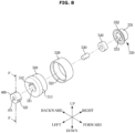
- FIG. 1 is a view illustrating a vacuum cleaner according to an embodiment of the disclosure.
- FIG. 2 is a perspective view illustrating a suction head of the vacuum cleaner according to an embodiment of the disclosure.
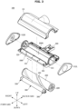
- FIG. 3 is an exploded view illustrating the suction head of the vacuum cleaner according to the embodiment of the disclosure.
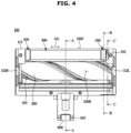
- FIG. 4 is a bottom view illustrating the suction head of the vacuum cleaner according to the embodiment of the disclosure.
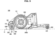
- FIG. 5 is a cross-sectional view along line A-A of FIG. 4 when viewed from the left side.
- a vacuum cleaner 1 may include a cleaner body 10, the suction head 100, and an extension tube 15 connecting the cleaner body 10 and the suction head 100.
- the cleaner body 10 may include a motor 11 that is a suction force generation device for generating a suction force, a foreign substance collection chamber 12 that separates foreign substances D from the suctioned air and collects the foreign substances D, a handle 13, and a battery 14 that may supply power to the motor 11.
- a motor 11 that is a suction force generation device for generating a suction force
- a foreign substance collection chamber 12 that separates foreign substances D from the suctioned air and collects the foreign substances D
- a handle 13 may supply power to the motor 11.
- the motor 11 functions to convert an electric force into a mechanical rotational force.
- a fan (not illustrated) that is connected to the motor 11 and rotates may be provided.
- the foreign substance collection chamber 12 may collect the foreign substances D through a cyclone method of separating the foreign substances D using a centrifugal force or a dust bag method of separating the foreign substances D by passing air through a filtration bag. The air which passes through the foreign substance collection chamber 12 and from which the foreign substance are removed may be discharged to the outside of the cleaner body 10.
- the extension tube 15 may be formed of a pipe having a predetermined rigidity or a flexible hose.
- the extension tube 15 may transfer, to the suction head 100, the suction force generated through the motor 11, and guide, to the cleaner body 10, the air and the foreign substances D suctioned through the suction head 100.
- the suction head 100 may suction the air and the foreign substances on a cleaning surface while in close contact with the cleaning surface. In detail, while moving forward, the suction head 100 may suction the foreign substances D scattered in front 100F of the suction head 100 into housings 111, 112L, 112R, and 113.
- the suction head 100 may be rotatably coupled to the extension tube 15.
- the suction head 100 may include the housings 111, 112L, 112R, and 113 between which a suction port 100B is formed, a drum brush 200 that rotates so that the foreign substances are effectively suctioned into the housings 111, 112L, 112R, and 113 through the suction port 100B, and a connector 16 connecting the housings 111, 112L, 112R, and 113 and the extension tube 15.
- the suction head 100 may further include a one-way roller 300 disposed in front of the drum brush 200.
- the suction head 100 may further include a plurality of wheel modules 500 that are arranged at both ends of the one-way roller 300 and assist forward/rearward movement of the suction head 100.
- the suction head 100 may further include an auxiliary wheel 600 that assists the forward/rearward movement of the suction head 100 together with the wheel modules 500.
- the auxiliary wheel 600 may be provided to be rotated by an auxiliary wheel shaft 610 fixed to the housings, particularly, the lower housing 113.
- the suction head 100 may be supported by the wheel modules 500 arranged in front of the drum brush 200 and the auxiliary wheel 600 disposed behind the drum brush 200.
- FIG. 4 illustrates a structure in which the suction head 100 is supported at three points by the plurality of wheel modules 500 and the auxiliary wheel 600, but the number of the wheel modules 500 and the number of the auxiliary wheel 600 are not limited thereto.
- the housings 111, 112L, 112R, and 113 may be formed by assembling the upper housing 111, the lower housing 113, the left side cover 112L, and the right side cover 112R.
- a bottom surface of the lower housing 113 is formed in an open shape so that the suction port 100B may be provided.
- the term "housing” may be used as a term referred to as the lower housing 113.
- the suction port 100B may be formed in the lower housing 113.
- the air and the foreign substances suctioned into the housings 111, 112L, 112R, and 113 through the suction port 100B may be transferred to the extension tube 15 through the connector 16.
- the foreign substances may be collected in the foreign substance collection chamber 12 through the extension tube.
- the suction port 100B may be formed to extend in a lengthwise direction of the housing.
- the connector 16 may be formed at the center of the housings 111, 112L, 112R, and 113 in the lengthwise direction 110.
- a connection port (not illustrated) connected to the connector 16 may be formed in the upper housing 111.
- a foreign substance removal pad (not illustrated) may be provided on an inner circumferential surface (not illustrated) of the upper housing 111.
- the drum brush 200 may be rotatably provided inside the housings 111, 112L, 112R, and 113.
- the drum brush 200 may be rotatably provided in the lower housing 113.
- Drum brush bearings 220 that assist a rotational movement of the drum brush 200 may be provided at both ends of a rotary shaft of the drum brush 200.
- a drum brush slot may be provided in the lower housing 113 such that the drum brush 200 is rotatably seated thereon.
- the drum brush slot may be provided in a circular shape to correspond to the shape of both sides of the drum brush 200.
- the shape of the drum brush slot is not limited thereto, and the drum brush slot may be formed in various shapes in which the drum brush 200 may be rotatably provided inside the lower housing 113, that is, the housings 111, 112L, 112R, and 113.
- the left side cover 112L and the right side cover 112R may be coupled to both side surfaces of the lower housing 113.
- the left side cover 112L and the right side cover 112R may be arranged on both side surfaces of the drum brush slot.
- the suction head 100 may include a driver (not illustrated) for providing a rotational force to rotate the drum brush 200.
- the drum brush 200 may include a cylindrical drum body and a brush provided on an outer circumferential surface of the drum body to sweep the cleaning surface and scatter the foreign substances.
- the brush may be fixedly inserted into a spiral seating groove formed in the outer circumferential surface of the drum body of the drum brush 200 so as to be fixed to the outer circumferential surface of the drum body.
- the foreign substances on the cleaning surface may be suctioned into the housings 111, 112L, 112R, and 113.
- the suction port 100B may be formed in the lower housing 113.
- the foreign substances D may be scattered to the upper side of the suction port 100B by the rotation of the drum brush 200.
- the air and the scattered foreign substances D suctioned into the housings 111, 112L, 112R, and 113 through the suction port 100B may be transferred to the extension tube 15 through the connector 16.
- the foreign substances may be collected in the foreign substance collection chamber 12 through the extension tube.
- the suction head 100 moves rearward, the foreign substances D may be separated and returned to the outside of the suction head 100 according to the positions of the foreign substances D in the suction head 100 during a cleaning process, and thus the cleaning may not be performed smoothly.
- a frequency is lower than in a case in which the suction head 100 moves rearward, this state may occur even when the suction head 100 moves forward.
- Such a cleaning state may occur more frequently as the size of the foreign substances to be suctioned becomes larger.
- the one-way roller 300 may be disposed in front of the drum brush 200 to prevent the foreign substances D from being separated and returned to the outside of the housing.
- the one-way roller 300 may rotate so that the foreign substances D move into the housings 111, 112L, 112R, and 113 when the suction head 100 moves forward and the rotation of the one-way roller 300 may be restricted so that the foreign substances D are not discharged to the outside of the housings 111, 112L, 112R, and 113 when the suction head 100 moves rearward (see FIGS. 3 and 4 ).
- a roller seat 120 may be formed in the lower housing 113 so that the one-way roller 300 may be rotatably seated in front of the drum brush 200.
- the one-way roller 300 may be disposed in close contact with the roller seat 120.
- a region 121 in which the roller seat 120 and the one-way roller 300 rub mutually while in close contact with each other may be formed.
- a diameter D1 of the one-way roller 300 may be formed smaller than the diameter of the drum brush 200.
- the plurality of wheel modules 500 rotatably supported by the one-way roller 300 may be provided at both ends of the one-way roller 300.
- the wheel modules 500 may also be rotatably supported by the lower housing 113.
- a structure in which the one-way roller 300 rotates so that the foreign substances D move into the housings 111, 112L, 112R, and 113 when the suction head 100 moves forward, and the rotation of the one-way roller 300 is restricted so that the foreign substances D are prevented from being discharged to the outside of the housings 111, 112L, 112R, and 113 when the suction head 100 moves rearward may be roughly implemented using two structures.
- the first structure may be implemented using the plurality of wheel modules 500 provided at both ends of the one-way roller 300 and rotatably supported by the one-way roller 300 and a one-way clutch bearing 400 fixed to the wheel modules 500.
- the one-way clutch bearing 400 may be provided to lock a roller shaft 310 that is a rotation axis of the one-way roller 300 when the suction head 100 moves forward and unlocks the roller shaft 310 when the suction head 100 moves rearward.
- a state in which the one-way clutch bearing 400 locks the roller shaft 310 may be a state in which a rotational force of the wheel modules 500 is transmitted to the one-way roller 300 and thus the one-way roller 300 also rotates.
- a state in which the one-way clutch bearing 400 unlocks the roller shaft 310 when the suction head 100 moves rearward may be a state in which the rotational force of the wheel modules 500 is not transmitted to the one-way roller 300, and thus even when the wheel modules 500 rotate, the one-way roller 300 may have a different motion state from the wheel modules 500.
- the second structure may be implemented using a close contact structure between the roller seat 120 and the one-way roller 300.
- the state in which the one-way clutch bearing 400 unlocks the roller shaft 310 when the suction head 100 moves rearward, and thus even when the wheel modules 500 rotate, the one-way roller 300 may have the different motion state from the wheel modules 500 may be the same as above.
- the rotation of the one-way roller 300 may be restricted by a frictional force caused by the close contact structure between the roller seat 120 and the one-way roller 300.
- the rotation of the one-way roller 300 is restricted, the foreign substances D are caught by the one-way roller 300 and thus may be provided so as not to be discharged to the outside of the housings 111, 112L, 112R, and 113.
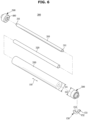
- FIG. 6 shows an exploded perspective view illustrating a one-way roller of the vacuum cleaner and a perspective view of a wheel module and a support hook according to an embodiment of the disclosure.
- FIG. 7 is an exploded perspective view illustrating the wheel module of the vacuum cleaner according to the embodiment of the disclosure.
- FIG. 8 illustrates the exploded perspective view of FIG. 7 when viewed in another direction.
- FIG. 9 is a cross-sectional view along line B-B of FIG. 4 when viewed from the left side.
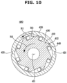
- FIG. 10 is a cross-sectional view along line F-F of FIG. 8 when viewed from the left side.
- the one-way roller 300 may include the roller shaft 310 and a roller body.
- the one-way roller 300 may further include a foreign substance contactor 330 disposed on an outer circumferential surface of the roller body 320.
- the roller shaft 310 may be formed in a cylindrical shape extending in a lengthwise direction 110 of the housing (see FIG. 4 ).
- the one-way roller 300 may further include insertion shafts 311 protruding from both ends at side surfaces of the roller shaft 310.
- the diameter of the insertion shafts 311 may be formed smaller than the diameter of the roller shaft 310. Similar to the roller shaft 310, the insertion shafts 311 may extend in the lengthwise direction 110 of the housing (see FIG. 4 ). Unlike this, the diameter of the insertion shafts 311 may be provided to be greater than or equal to the diameter of the roller shaft 310.
- the insertion shafts 311 may be inserted into the one-way clutch bearing 400 which will be described below.
- the insertion shafts 311 may be fixed to inner races 410 of the one-way clutch bearings 400. A detailed structural relationship between the insertion shaft 311 and the one-way clutch bearing 400 will be described below.
- the roller body 320 may be formed in a cylindrical shape extending in the lengthwise direction 110 of the housing.
- the roller body 320 may include a hollow formed in the center thereof in the lengthwise direction 110 of the housing.
- An extension length of the roller body 320 may be provided in a length corresponding to the roller shaft 310.
- the extension length of the roller body 320 may be provided the same as the extension length of the roller shaft 310.
- the roller shaft 310 may be disposed in the hollow of the roller body 320.
- the roller body 320 and the roller shaft 310 may be fixed in close contact with each other.
- the foreign substance contactor 330 may be disposed on the outer circumferential surface of the roller body 320.
- the foreign substance contactor 330 may be provided as a villus.
- the villus may be formed in a form in which fine hairs extend in a radial direction from the outer circumferential surface of the roller body 320. That is, each of the fine hairs may be provided in the form of being densely embedded in the outer circumferential surface of the roller body 320.
- the villus may be made of a nylon-based material. Alternatively, the villus may be formed of an anti-static material. Alternatively, the villus may be formed of a carbon-based soft sole.
- the villus may be formed of a rubber tube rather than a shape of the villus formed by gathering the fine hairs.
- the foreign substance contactor 330 may be disposed on the outer circumferential surface of the roller shaft 310. That is, in the one-way roller 300, the roller body 320 may be omitted.
- the wheel modules 500 may be arranged at both ends of the one-way roller 300.
- the wheel modules 500 may be provided to support the roller shaft 310 that is a rotary shaft of the one-way roller.
- the wheel modules 500 may be provided to support the insertion shafts 311 protruding from both ends of the roller shaft 310.
- One side of the wheel modules 500 may be inserted into the insertion shaft 311.
- the insertion shaft 311 may be inserted into the one-way clutch bearing 400 provided on one side of the wheel modules 500.
- the insertion shaft 311 may be fixedly inserted into a rotation center portion of the one-way clutch bearing 400 fixed to the one side of the wheel modules 500. The detailed structural relationship between the insertion shaft 311 and the one-way clutch bearing 400 will be described below.
- the wheel modules 500 may be arranged at both ends of the one-way roller 300, and a diameter D2 of the wheel modules 500 may be provided greater than the diameter D1 of the one-way roller 300.
- the wheel modules 500 may be provided to support the roller shaft 310 that is a rotary shaft of the one-way roller.
- the one-way roller 300 may be provided in a structure having a separation distance g (see FIG. 5 ) from the cleaning surface G.
- the structure having the separation distance g from the cleaning surface G is to prevent the one-way roller 300 from being in complete contact with the cleaning surface G and thus being affected due to the complete contact.
- the wheel module 500 may include a wheel frame 510 and an outer cover member 520.
- the wheel frame 510 may be formed in a substantially cylindrical shape.
- the outer cover member 520 may be disposed on an outer circumferential surface of the wheel frame 510.
- the outer cover member 520 may be provided in a shape corresponding to the outer circumferential surface of the wheel frame 510.
- the outer cover member 520 may perform the same function as a tire of a vehicle.
- the outer cover member 520 may be formed of a material capable of improving a frictional force when in contact with the cleaning surface G.
- the outer cover member 520 may be formed of a rubber material to improve the frictional force when in contact with the cleaning surface G.
- the outer cover member 520 may be secondarily injected, and thus the wheel module 500 may be formed. That is, for continuous injection, the outer cover member 520 may be injected but may be formed using, as an injection-molded material, a material having a higher frictional coefficient than that of the primarily injected wheel frame 510.
- a step 513 may be formed on an outer circumferential surface of the wheel frame 510.
- the wheel frame may be more tightly coupled to the outer cover member 520.
- a step 521 may be formed even on an inner circumferential surface of the outer cover member 520.
- the step 521 on the inner circumferential surface of the outer cover member may be formed to correspond to the step 513 on the outer circumferential surface of the wheel frame.
- the wheel module 500 may further include a wheel shaft 530 and a wheel bearing 540 for supporting the wheel shaft 530.
- the wheel module 500 may further include a cap bearing 550 for covering the wheel bearing 540.
- the one-way clutch bearing 400 may be disposed on one side surface of the wheel frame 510.
- the wheel shaft 530 may protrude from the other side surface of the wheel frame 510 and may be provided as a rotary shaft of the wheel frame 510.
- a method in which the wheel shaft 530 protrudes may be provided in a structure in which a wheel shaft insertion groove 514 into which the wheel shaft 530 may be inserted is formed in the other side surface of the wheel frame 510 and the wheel shaft 530 is inserted into the wheel shaft insertion groove 514.
- the wheel shaft 530 is inserted into the wheel shaft insertion groove 5144 so that the wheel shaft 530 may be fixed to the wheel frame 510.
- the wheel shaft 530 may be integrally formed with the wheel frame 510. That is, when the wheel frame 510 is injected, the wheel shaft 530 may also be injection-molded.
- the wheel shaft 530 may be rotatably supported by the lower housing 113 immediately after being fixed to the other side surface of the wheel frame 510.
- the wheel bearing 540 may be provided.
- the wheel shaft 530 may be inserted into and supported by the wheel bearing 540.
- the wheel bearing 540 may be disposed on an outer circumferential surface of the wheel shaft 530, and the wheel bearing 540 may be supported by the lower housing 113.
- the cap bearing 550 may be provided.
- the wheel bearing 540 may be inserted into and supported by the cap bearing 550.
- the cap bearing 550 may be disposed on an outer circumferential surface of the wheel bearing 540, and the wheel bearing 540 may be supported by the lower housing 113. Unlike this, the wheel bearing 540 may also be rotatably supported by the lower housing 113 immediately after the wheel shaft 530 is inserted.
- a wheel bearing insertion groove 553 may be formed in one surface of the cap bearing 550.
- the wheel bearing 540 may be inserted into the wheel bearing insertion groove 553.
- the wheel bearing 540 may be inserted into the wheel bearing insertion groove 553 of the cap bearing, and the cap bearing 550 may be provided to surround the wheel bearing 540. Since the cap bearing 550 is provided to surround the wheel bearing 540, durability of the wheel bearing 540 can be secured. Since the cap bearing 550 is provided to surround the wheel bearing 540, a defect in the rotational movement of the wheel module 500 due to the foreign substances accumulated around the wheel shaft 530 of the wheel module 500 can be prevented.
- the cap bearing 550 may include a contactor 551 and a visor 552 with a wheel bearing seat 553 of the lower housing 113, which will be described below.
- the visor 552 may be formed in a shape corresponding to the other side surface of the wheel frame 510.
- the visor 552 may be provided to cover the entirety of the other side surface of the wheel frame 510 and prevent the foreign substances from being accumulated around the wheel shaft 530.
- a cap bearing body 551 seated on the wheel bearing seat 553 of the lower housing 113 may be provided in a substantially cylindrical shape. That is, the cap bearing 550 in which the cap bearing body 551 and the visor 552 are integrally formed may be formed in a substantial fedora shape.
- An overrunning clutch may be applied to the one-way clutch bearing 400.
- the overrunning clutch refers to a clutch that transmits a driving force only in one direction. For example, when an outer ring of the clutch rotates in one direction, a rotational force is transmitted to an inner ring of the clutch so that both of the outer ring of the clutch and the inner ring of the clutch may rotate. On the other hand, when the outer ring of the clutch rotates in the other direction opposite to the one direction, the rotational force is not transmitted to the inner ring of the clutch. Thus, the outer ring of the clutch and the inner ring of the clutch may maintain different movement states.
- the one-way clutch bearing 400 may be disposed on one side surface of the wheel frame 510.
- the one-way clutch bearing 400 may be inserted into a wheel frame groove 511 formed in the one side surface of the wheel frame 510.
- the wheel frame groove 511 may be formed in a shape corresponding to an outer circumferential surface of the one-way clutch bearing 400.
- the one-way clutch bearing 400 may be fixed after being inserted into the wheel frame groove 511.
- a seating groove 421 may be formed in the outer circumferential surface of the one-way clutch bearing 400.
- the seating groove 421 may be formed in an outer circumferential surface of an outer race 420 of the one-way clutch bearing 400.
- a one-way clutch bearing fixer 512 may be formed on an inner circumferential surface of the wheel frame groove 511 formed in the one side surface of the wheel frame 510 to correspond to the seating groove 421.
- the seating groove 421 and the one-way clutch bearing fixer 512 may be formed in a direction in which a rotation axis of the wheel module 500 is placed.
- the one-way clutch bearing 400 may be inserted into the wheel frame groove 511, and the seating groove 421 and the one-way clutch bearing fixer 512 may mesh with each other.
- the roller shaft 310 of the one-way roller 300 may be inserted into the one-way clutch bearing 400.
- the roller shaft 310 may be fixedly inserted into a roller shaft fixer 411 that is an inner circumferential surface of the inner race 410 of the one-way clutch bearing 400.
- the one-way clutch bearing 400 may include the outer race 420, the inner race 410, and a bearing roller 440.
- the outer race 420 may be formed roughly in a cylindrical shape including a hollow in the center thereof.
- the inner race 410 may be inserted into the hollow of the outer race 420 and rotatably provided inside the outer race 420.
- a bearing roller seat 120 into which the bearing roller 440 may be inserted may be formed between an outer circumferential surface of the inner race 410 and an inner circumferential surface of the outer race 420.
- the inner race 410 include a bearing roller supporter 412 protruding from the outer circumferential surface of the inner race 410 to support the bearing roller 440 by forming the bearing roller seat 120.
- the inner race 410 may be formed in a substantially sawtooth shape.
- the bearing roller seat 120 may be formed in a tapered structure that gradually becomes narrower in a movement direction D3 of the bearing roller 440 when the suction head 100, which will be described below, moves forward.
- the seating groove 421 may be formed in the outer circumferential surface of the outer race 420 of the one-way clutch bearing 400. It is illustrated that two seating grooves 521 are formed. However, for firm coupling between the one-way clutch bearing 400 and the wheel module 500, the number of the seating grooves 521 is not limited to two.
- the wheel frame 510 of the wheel module 500 and the one-way clutch bearing 400 may be fixed to each other.
- the wheel module 500 in contact with the cleaning surface G may rotate in a direction R1
- the outer race 420 may also rotate in the direction R1. That is, when the suction head 100 moves forward, a rotation direction of the wheel module 500 and a rotation direction of the outer race 420 may be defined as the "direction R1 (see FIG. 14 ).
- the bearing roller 440 may move in a direction R3. That is, when the suction head 100 moves forward, a movement direction of the bearing roller 440 may be defined as a "direction R2.”
- the bearing roller seat 120 may be formed in a tapered structure that gradually becomes narrower in the movement direction R3 of the bearing roller 440 when the suction head 100, which will be described below, moves forward.
- the bearing roller 440 may move in the direction R3 and come into contact with the inner circumferential surface of the outer race 420 and the outer circumferential surface of the inner race 410.
- a rotational force of the outer race 420 may be transferred to the inner race 410.
- the inner race 410 rotates in the direction R2.
- the roller shaft 310 may be fixedly inserted into the roller shaft fixer 411 that is the inner circumferential surface of the inner race 410 of the one-way clutch bearing 400, which will be described below.
- the roller shaft 310 may also rotate in the direction R2.
- the one-way roller 300 may also rotate in the direction R2. That is, when the suction head 100 moves forward, a rotation direction of the inner race 410 and a rotation direction of the one-way roller 300 may be defined as the "direction R2.”
- This state may be defined as a state in which the one-way clutch bearing 400 locks the roller shaft 310 that is the rotation axis of the one-way roller 300 when the suction head 100 moves forward.
- a state in which the one-way clutch bearing 400 locks the roller shaft 310 may be a state in which the rotational force of the wheel modules 500 is transmitted to the one-way roller 300 and thus the one-way roller 300 also rotates.
- the rotational force of the outer race 420 may not be transferred to the inner race 410.
- the outer race 420 and the inner race 410 may maintain different movement states.
- the wheel module 500 and the one-way roller 300 may maintain different movement states.
- the one-way roller 300 is fixed, and only the wheel module 500 may rotate.
- This state may be defined as a state in which the one-way clutch bearing 400 unlocks the roller shaft 310 that is the rotation axis of the one-way roller 300 when the suction head 100 moves rearward.
- the state in which the one-way clutch bearing 400 unlocks the roller shaft 310 may be a state in which the rotational force of the wheel module 500 is not transmitted to the one-way roller 300, and thus even when the wheel module 500 rotates, the one-way roller 300 may have a different motion state from the wheel modules 500.
- the one-way roller 300, the one-way clutch bearing 400, and the wheel module 500 may share one rotation axis and may be connected to each other in a straight line. That is, the roller shaft 310 of the one-way roller 300 may be connected to the one-way clutch bearing 400 through the insertion shaft 311.
- the insertion shaft 311 may be fixed to the roller shaft fixer 411 that is the inner circumferential surface of the inner race 410 of the one-way clutch bearing 400.
- the one-way clutch bearing 400 may be fixed to the wheel frame groove 511 formed at one side of the wheel frame 510 of the wheel module 500.
- the same wheel modules 500 are arranged at both ends of the one-way roller 300.
- the wheel module 500 may be disposed only at one of both ends of the one-way roller 300, and thus the above-described locking or unlocking power transmission structure can be implemented.
- the one-way roller 300, the one-way clutch bearing 400, and the wheel module 500 connected to each other in a straight line may be seated on the lower housing 113.
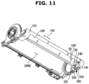
- FIG. 11 is a perspective view illustrating a bottom surface of a lower housing of the suction head of the vacuum cleaner according to an embodiment of the disclosure.
- FIG. 12 is a bottom view illustrating the lower housing of the suction head of the vacuum cleaner according to the embodiment of the disclosure.
- FIG. 13 is a cross-sectional view along line C-C of FIG. 4 when viewed from the left side.
- the lower housing 113 may include the roller seat 120 in which the one-way roller 300 is disposed.
- the roller seat 120 may be formed in front of a position at which the drum brush 200 is disposed.
- An inner circumferential surface of the roller seat 120 may be formed in a shape corresponding to an upper outer circumferential surface of the one-way roller 300 to be in close contact with the one-way roller 300.
- the inner circumferential surface of the roller seat 120 may be formed in a shape corresponding to an outer circumferential surface of the foreign substance contactor 330.
- the inner circumferential surface of the roller seat 120 may be formed in a substantially cylindrical shape.
- the region 121 in which the roller seat 120 and the foreign substance contactor 330 rub mutually while in close contact with each other may be formed.
- the region 121 in which the roller seat 120 and the one-way roller 300 rub mutually while in close contact with each other may be formed to correspond to half of the outer circumferential surface of the one-way roller 300.
- the lower housing 113 may include a wheel seat 130 which is formed on one side of the roller seat 120 and accommodates the wheel module 500.
- the wheel seat 130 may be formed in a shape corresponding to the wheel module 500, particularly, an outer circumferential surface of the outer cover member 520.
- a step may be formed at a portion extending from the roller seat 120 to the wheel seat 130. This may be defined as a step 23 between the roller seat 120 and the wheel seat 130.
- the wheel seat 130 may not be in close contact with the wheel module 500 and may be spaced apart from the wheel module 500. Through this structure, the wheel module 500 may smoothly rotate.
- the lower housing 113 may further include a wheel bearing seat 553 which is formed on one side of the wheel seat 130 and in which the wheel bearing 540 is seated.
- a wheel bearing seat 553 which is formed on one side of the wheel seat 130 and in which the wheel bearing 540 is seated.
- the cap bearing 550 surrounding the wheel bearing 540 may be disposed on the outer circumferential surface of the wheel bearing 540, an inner circumferential surface of the wheel bearing seat 553 may be in contact with the cap bearing body 551 of the cap bearing 550.
- a step may be formed at a portion extending from the wheel seat 130 to the wheel bearing seat 553. This may be defined as a step 34 between the wheel seat 130 and the wheel bearing seat 553.
- the wheel bearing seat 553 may include an opening 141 that is open to face the bottom surface of the lower housing 113.
- a plurality of wheel bearing seats 553 may be formed to correspond to the number of the wheel modules 500, and the opening 141 may be formed in only some of the plurality of wheel bearing seats 553.
- FIGS. 11 and 12 illustrate that an opening is formed in the wheel bearing seat 553 formed adjacent to the left side cover 112L, but the disclosure is not limited thereto.
- the suction head 100 may further include a support hook 150 so that the one-way roller 300 and the wheel module 500 connected to each other in a straight line may be fixedly arranged in the roller seat 120, the wheel seat 130, and the wheel bearing seat 553.
- the support hook 150 may be formed in a substantially hook shape.
- the support hook 150 may be provided to close the opening 141 and support the wheel bearing 540 seated in the wheel bearing seat 553.
- the cap bearing 550 surrounding the wheel bearing 540 may be disposed on the outer circumferential surface of the wheel bearing 540, an inner circumferential surface 152 of the support hook 150 and the cap bearing body 551 of the cap bearing 550 may be in contact with each other.
- One end of the support hook 150 may be rotatably coupled to the lower housing 113.
- the support hook 150 may rotate about a support hook rotary shaft 151.
- a fastening protrusion 153 may be formed at the other end of the support hook 150 so that the support hook 150 may be fixedly hooked to the lower housing 113.
- a fastening groove 142 may be provided in the lower housing 113 at a position corresponding to the fastening protrusion 153.
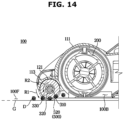
- FIG. 14 is a part of the cross-sectional view of FIG. 5 for describing an operation process when the suction head of the vacuum cleaner according to the embodiment of the disclosure moves forward.
- FIG. 15 is a part of the cross-sectional view of FIG. 5 for describing an operation process when the suction head of the vacuum cleaner according to the embodiment of the disclosure moves rearward.
- the suction head 100 moves forward, since the outer cover member 520 of the wheel module 500 is in contact with the cleaning surface G, the outer cover member 520 rotates in the direction R1.
- the suction head 100 moves forward, since the one-way clutch bearing 400 and the roller shaft 310 of the one-way roller 300 are locked, the one-way roller 300 and the wheel module 500 rotate in the same direction. That is, even when a frictional force is applied to the region 121 in which the roller seat 120 and the one-way roller 300 rub mutually while in close contact with each other, a larger rotational force transmitted from the wheel module 500 is applied, and thus the one-way roller 300 and the wheel module 500 may rotate in the same direction.
- the one-way roller 300 comes into contact with the foreign substances D on the cleaning surface G while rotating, and the foreign substances are introduced into the housings 111, 112L, 112R, and 113 in the direction R2 that is the rotational direction of the one-way roller 300.
- the one-way roller 300 tries to maintain a rotational state in the direction R2 illustrated in FIG. 14 due to a rotation inertia force in a forward state, and after a certain time has elapsed, the rotation of the one-way roller 300 is restricted due to a frictional force of the region 121 in which the roller seat 120 and the one-way roller 300 rub mutually while in close contact with each other. That is, a state of being fixed to the lower housing 113 is maintained due to the frictional force of the region 121 in which the roller seat 120 and the one-way roller 300 rub mutually while in close contact with each other. In particular, since the one-way roller 300 is spaced apart from the cleaning surface G, a frictional force with the cleaning surface G is not applied.
Landscapes
- Engineering & Computer Science (AREA)
- Mechanical Engineering (AREA)
- Nozzles For Electric Vacuum Cleaners (AREA)
Claims (13)
- Staubsauger (1), umfassend:einen Reinigerkörper (10), der einen Motor (11), der dazu konfiguriert ist, eine Saugkraft zu erzeugen, und eine Fremdstoffsammelkammer (12) beinhaltet; undeinen Saugkopf (100), der mit dem Reinigerkörper verbunden ist und Folgendes beinhaltet:ein Gehäuse (111, 112L, 112R, 113) mit einer Saugöffnung (100B),eine Trommelbürste (200) undeine Einwegwalze (300), die vor der Trommelbürste (200) angeordnet ist,wobei die Trommelbürste und die Einwegwalze so konfiguriert sind, dass,wenn sich der Saugkopf (100) auf einer zu reinigenden Oberfläche (G) vorwärts bewegt, sich die Trommelbürste (200) und die Einwegwalze (300) drehen, so dass Fremdstoffe auf der Oberfläche durch die Saugkraft durch die Saugöffnung in das Gehäuse gesaugt und zur Fremdstoffsammelkammer (12) geleitet werden, undwenn sich der Saugkopf (100) auf der Oberfläche rückwärts bewegt, die Drehung der Einwegwalze (300) eingeschränkt wird, um zu verhindern, dass die in das Gehäuse gesaugten Fremdstoffe (D) durch die Saugöffnung außerhalb des Gehäuses des Saugkopfes ausgestoßen werden,wobei die Einwegwalze Folgendes beinhaltet:eine Walzenwelle (310), undeinen Walzenkörper (320), der an einer äußeren Umfangsfläche der Walzenwelle befestigt ist und so konfiguriert ist, dass der Walzenkörper, wenn sich der Saugkopf auf der Oberfläche befindet, zumindest mit einigen der Fremdstoffe auf der Oberfläche unter dem Saugkopf in Kontakt steht,wobei der Staubsauger ferner ein Einwegkupplungslager (400) beinhaltet, das mit mindestens einem Ende der Walzenwelle verbunden ist und dazu konfiguriert ist, das mindestens eine Ende der Walzenwelle zu stützen.
- Staubsauger nach Anspruch 1, wobei das Einwegkupplungslager (400) die Walzenwelle (310) verriegelt, so dass sich die Walzenwelle während der Vorwärtsbewegung des Saugkopfes dreht, und die Walzenwelle entriegelt, so dass die Walzenwelle während der Rückwärtsbewegung des Saugkopfes an einer Drehung gehindert wird.
- Staubsauger nach Anspruch 1, wobei die Einwegwalze (300) ferner einen Fremdstoffkontaktor (330) beinhaltet, der an einer äußeren Umfangsfläche des Walzenkörpers (320) angeordnet ist, oder wobei der Walzenkörper (320) den Fremdstoffkontaktor (330) umfasst, wobei der Fremdstoffkontaktor (330) eine Zotte umfasst, die dazu konfiguriert ist, wenn sich der Saugkopf (100) auf der Oberfläche befindet, mit zumindest einigen der Fremdstoffe (D) auf der Oberfläche unter dem Saugkopf in Kontakt zu kommen.
- Staubsauger nach Anspruch 1, ferner umfassend ein Radmodul (500), das an mindestens einem Ende der Einwegwalze angeordnet ist, an dem die Walzenwelle (310) mit dem Einwegkupplungslager (400) verbunden ist, und das dazu konfiguriert ist, mindestens ein Ende der Walzenwelle durch das Einwegkupplungslager zu stützen.
- Staubsauger nach Anspruch 4, wobei das Radmodul beinhaltet:einen Radrahmen (510), an dem das Einwegkupplungslager (400) an einer inneren Seitenfläche des Radrahmens befestigt ist;eine Radwelle (530), die von einer äußeren Seitenfläche des Radrahmens vorsteht und als Drehwelle des Radrahmens konfiguriert ist; undein Radlager (540), das die Radwelle stützt.
- Staumbsauger nach Anspruch 5, wobeisich das Radmodul (500) und die Einwegwalze (300) drehen, wenn sich der Saugkopf vorwärts bewegt, unddie Einwegwalze (300) gehindert wird, sich zu bewegen, und sich das Radmodul (500) dreht, wenn sich der Saugkopf rückwärts bewegt.
- Staubsauger nach Anspruch 6, wobei das Gehäuse (112L, 112R) einen Walzensitz (120) beinhaltet, in dem die Einwegwalze (300) angeordnet ist, und
eine innere Umfangsfläche des Walzensitzes (120) in einer solchen Form bereitgestellt ist, dass eine obere äußere Umfangsfläche der Einwegwalze (300) mit die Einwegwalze in Kontakt kommt, um Reibung zwischen der inneren Umfangsfläche des Walzensitzes (120) und der oberen äußeren Umfangsfläche der Einwegwalze bereitzustellen. - Staubsauger nach Anspruch 7, wobei das Gehäuse ferner Folgendes umfasst:einen Radsitz (130), der auf einer Seite des Walzensitzes (120) ausgebildet ist und das Radmodul (500) aufnimmt; undeinen Radlagersitz (553), der an einer Außenseite des Radsitzes ausgebildet ist und in dem das Radlager (540) sitzt.
- Staubsauger nach Anspruch 8, wobei der Radlagersitz (553) eine Öffnung (141) beinhaltet, die einer Bodenfläche des Gehäuses zugewandt ist, und
der Staubsauger ferner einen Stützhaken (150) beinhaltet, der dazu konfiguriert ist, die Öffnung zu schließen und das im Radlagersitz sitzende Radlager zu stützen, wobei der Stützhaken ein Ende, das drehbar mit dem Gehäuse verbunden ist, und ein anderes Ende aufweist, das mit dem Gehäuse so verbunden ist, dass es das Radlager (540) stützt. - Staubsauger nach Anspruch 5, wobei der Radrahmen (510) eine Radrahmennut (511) beinhaltet, die in der Innenfläche des Radrahmens ausgebildet ist, so dass das Einwegkupplungslager (400) fest in die Radrahmennut (511) eingesetzt ist.
- Staubsauger nach Anspruch 4, wobei ein Durchmesser des Radmoduls (500) größer ist als ein Durchmesser der Einwegwalze (300).
- Staubsauger nach Anspruch 5, ferner umfassend:eine Vielzahl der Radmodule (500),wobei mindestens ein Radmodul der Vielzahl von Radmodulen ferner ein äußeres Abdeckungselement (520) beinhaltet, das an einer äußeren Umfangsfläche des Radrahmens des Radmoduls befestigt ist und diese umgibt.
- Staubsauger nach Anspruch 12, wobei das äußere Abdeckungselement (520) so ausgebildet ist, dass es mit der Oberfläche in Kontakt kommt, wenn sich der Saugkopf auf der Oberfläche befindet, und aus einem Gummimaterial gebildet ist, um die Reibungskraft mit der Oberfläche zu erhöhen.
Applications Claiming Priority (2)
| Application Number | Priority Date | Filing Date | Title |
|---|---|---|---|
| KR1020200085336A KR20220007295A (ko) | 2020-07-10 | 2020-07-10 | 진공 청소기 |
| PCT/KR2021/005864 WO2022010083A1 (ko) | 2020-07-10 | 2021-05-11 | 진공 청소기 |
Publications (4)
| Publication Number | Publication Date |
|---|---|
| EP4133982A1 EP4133982A1 (de) | 2023-02-15 |
| EP4133982A4 EP4133982A4 (de) | 2023-10-11 |
| EP4133982B1 true EP4133982B1 (de) | 2025-01-01 |
| EP4133982C0 EP4133982C0 (de) | 2025-01-01 |
Family
ID=79553308
Family Applications (1)
| Application Number | Title | Priority Date | Filing Date |
|---|---|---|---|
| EP21837615.0A Active EP4133982B1 (de) | 2020-07-10 | 2021-05-11 | Staubsauger |
Country Status (5)
| Country | Link |
|---|---|
| US (1) | US12364375B2 (de) |
| EP (1) | EP4133982B1 (de) |
| KR (1) | KR20220007295A (de) |
| CN (1) | CN115768323A (de) |
| WO (1) | WO2022010083A1 (de) |
Families Citing this family (4)
| Publication number | Priority date | Publication date | Assignee | Title |
|---|---|---|---|---|
| EP4059398A1 (de) * | 2021-03-17 | 2022-09-21 | Koninklijke Philips N.V. | Zuführung von flüssigkeit zu mindestens einem rad eines saugkopfes |
| EP4059405A1 (de) * | 2021-03-17 | 2022-09-21 | Koninklijke Philips N.V. | Saugkopf zur verwendung in einem staubsauger |
| GB2614914B (en) * | 2022-01-25 | 2024-07-10 | Dyson Technology Ltd | Cleaner head for a vacuum cleaner |
| KR102747811B1 (ko) * | 2022-03-14 | 2024-12-31 | 주식회사 고원인더스트리 | 진공청소기 헤드 |
Family Cites Families (14)
| Publication number | Priority date | Publication date | Assignee | Title |
|---|---|---|---|---|
| US4658458A (en) * | 1986-04-16 | 1987-04-21 | Shop-Vac Corporation | Rotary brush sweeper with mechanism for brush height adjustment |
| KR100556811B1 (ko) * | 2004-06-12 | 2006-03-10 | 엘지전자 주식회사 | 진공청소기의 흡입헤드 |
| JP2006110089A (ja) * | 2004-10-14 | 2006-04-27 | Toshiba Tec Corp | 吸込口体および電気掃除機 |
| US8117714B2 (en) * | 2005-03-09 | 2012-02-21 | Bissell Homecare, Inc. | Vacuum cleaner with hair collection element |
| US8402600B2 (en) * | 2006-12-13 | 2013-03-26 | Ab Electrolux | Vacuum cleaner nozzle and roller |
| US20090000057A1 (en) * | 2007-01-24 | 2009-01-01 | Samsung Gwangju Electronics Co., Ltd | Suction nozzle assembly usable with vacuum cleaner having hair collecting member, vacuum cleaner having the same, and method for removing hair by using the same |
| KR101525597B1 (ko) * | 2008-11-03 | 2015-06-02 | 삼성전자주식회사 | 노즐조립체 및 이를 가지는 진공청소기 |
| KR20100093325A (ko) * | 2009-02-16 | 2010-08-25 | 삼성광주전자 주식회사 | 진공청소기의 브러시 조립체 |
| WO2011083294A1 (en) * | 2010-01-08 | 2011-07-14 | Dyson Technology Limited | A cleaner head |
| AU2014100004A4 (en) | 2013-01-11 | 2014-01-30 | Bissell Inc. | Vacuum cleaner |
| JP6093662B2 (ja) * | 2013-07-03 | 2017-03-08 | 日立アプライアンス株式会社 | 電気掃除機の吸口体およびそれを用いた電気掃除機 |
| JP6078427B2 (ja) * | 2013-07-04 | 2017-02-08 | 日立アプライアンス株式会社 | 電気掃除機の吸口体およびそれを用いた電気掃除機 |
| JP2018534040A (ja) * | 2015-10-26 | 2018-11-22 | コーニンクレッカ フィリップス エヌ ヴェKoninklijke Philips N.V. | 電気掃除機ヘッド |
| JP6781509B2 (ja) * | 2017-04-20 | 2020-11-04 | 日立グローバルライフソリューションズ株式会社 | 電気掃除機の吸口体 |
-
2020
- 2020-07-10 KR KR1020200085336A patent/KR20220007295A/ko active Pending
-
2021
- 2021-05-11 EP EP21837615.0A patent/EP4133982B1/de active Active
- 2021-05-11 CN CN202180045349.5A patent/CN115768323A/zh active Pending
- 2021-05-11 WO PCT/KR2021/005864 patent/WO2022010083A1/ko not_active Ceased
-
2022
- 2022-11-23 US US17/993,588 patent/US12364375B2/en active Active
Also Published As
| Publication number | Publication date |
|---|---|
| WO2022010083A1 (ko) | 2022-01-13 |
| CN115768323A (zh) | 2023-03-07 |
| US20230087015A1 (en) | 2023-03-23 |
| US12364375B2 (en) | 2025-07-22 |
| KR20220007295A (ko) | 2022-01-18 |
| EP4133982C0 (de) | 2025-01-01 |
| EP4133982A1 (de) | 2023-02-15 |
| EP4133982A4 (de) | 2023-10-11 |
Similar Documents
| Publication | Publication Date | Title |
|---|---|---|
| EP4133982B1 (de) | Staubsauger | |
| JP4097264B2 (ja) | 電気掃除機 | |
| US9074622B2 (en) | Disposable bag and a disposable bag mount bracket for an upright vacuum cleaner | |
| US11564541B2 (en) | Vacuum cleaner | |
| JP2003250727A (ja) | 叩き用回転ローラを具備した真空掃除機用吸込ブラシ組立体 | |
| US9949602B2 (en) | Vacuum axle with a motor embedded therein and wheels | |
| CN101091632B (zh) | 电动吸尘器 | |
| KR102707557B1 (ko) | 청소기 및 청소기의 브러시 드럼 제조방법 | |
| US6918155B2 (en) | Dual agitator drive system with worm gear | |
| CA2790359A1 (en) | Efficient lightweight vacuum | |
| CN214048668U (zh) | 真空吸尘器 | |
| US20060288521A1 (en) | Electric vacuum cleaner | |
| US20130111694A1 (en) | Lightweight vacuum cleaner | |
| KR20210069405A (ko) | 진공 청소기 | |
| JP2021145943A (ja) | 電気掃除機の吸込口体およびそれを備えた電気掃除機 | |
| JP4130162B2 (ja) | 吸込口体および電気掃除機 | |
| JP5622830B2 (ja) | 電気掃除機の吸口体 | |
| JP7593686B1 (ja) | 吸込具及び電気掃除機 | |
| JP2006020895A (ja) | 電気掃除機 | |
| JP2026000658A (ja) | 吸込口部、吸込口体及び電気掃除機 | |
| CN121752162A (zh) | 吸尘器吸嘴 | |
| CN121752161A (zh) | 吸尘器吸嘴 | |
| JP2026000660A (ja) | 吸込口体及び電気掃除機 | |
| JP2021159503A (ja) | 電気掃除機用吸込口体の回転清掃体、それを備えた吸込口体および電気掃除機 | |
| JP5154628B2 (ja) | 電気掃除機の吸口体及びこれを用いた電気掃除機 |
Legal Events
| Date | Code | Title | Description |
|---|---|---|---|
| STAA | Information on the status of an ep patent application or granted ep patent |
Free format text: STATUS: THE INTERNATIONAL PUBLICATION HAS BEEN MADE |
|
| PUAI | Public reference made under article 153(3) epc to a published international application that has entered the european phase |
Free format text: ORIGINAL CODE: 0009012 |
|
| STAA | Information on the status of an ep patent application or granted ep patent |
Free format text: STATUS: REQUEST FOR EXAMINATION WAS MADE |
|
| 17P | Request for examination filed |
Effective date: 20221111 |
|
| AK | Designated contracting states |
Kind code of ref document: A1 Designated state(s): AL AT BE BG CH CY CZ DE DK EE ES FI FR GB GR HR HU IE IS IT LI LT LU LV MC MK MT NL NO PL PT RO RS SE SI SK SM TR |
|
| A4 | Supplementary search report drawn up and despatched |
Effective date: 20230908 |
|
| RIC1 | Information provided on ipc code assigned before grant |
Ipc: A47L 5/28 20060101ALI20230904BHEP Ipc: A47L 9/04 20060101AFI20230904BHEP |
|
| DAV | Request for validation of the european patent (deleted) | ||
| DAX | Request for extension of the european patent (deleted) | ||
| GRAP | Despatch of communication of intention to grant a patent |
Free format text: ORIGINAL CODE: EPIDOSNIGR1 |
|
| STAA | Information on the status of an ep patent application or granted ep patent |
Free format text: STATUS: GRANT OF PATENT IS INTENDED |
|
| INTG | Intention to grant announced |
Effective date: 20240801 |
|
| GRAS | Grant fee paid |
Free format text: ORIGINAL CODE: EPIDOSNIGR3 |
|
| GRAA | (expected) grant |
Free format text: ORIGINAL CODE: 0009210 |
|
| STAA | Information on the status of an ep patent application or granted ep patent |
Free format text: STATUS: THE PATENT HAS BEEN GRANTED |
|
| AK | Designated contracting states |
Kind code of ref document: B1 Designated state(s): AL AT BE BG CH CY CZ DE DK EE ES FI FR GB GR HR HU IE IS IT LI LT LU LV MC MK MT NL NO PL PT RO RS SE SI SK SM TR |
|
| REG | Reference to a national code |
Ref country code: GB Ref legal event code: FG4D |
|
| REG | Reference to a national code |
Ref country code: DE Ref legal event code: R096 Ref document number: 602021024461 Country of ref document: DE |
|
| REG | Reference to a national code |
Ref country code: CH Ref legal event code: EP |
|
| REG | Reference to a national code |
Ref country code: IE Ref legal event code: FG4D |
|
| U01 | Request for unitary effect filed |
Effective date: 20250127 |
|
| U07 | Unitary effect registered |
Designated state(s): AT BE BG DE DK EE FI FR IT LT LU LV MT NL PT RO SE SI Effective date: 20250131 |
|
| U20 | Renewal fee for the european patent with unitary effect paid |
Year of fee payment: 5 Effective date: 20250523 |
|
| PG25 | Lapsed in a contracting state [announced via postgrant information from national office to epo] |
Ref country code: PL Free format text: LAPSE BECAUSE OF FAILURE TO SUBMIT A TRANSLATION OF THE DESCRIPTION OR TO PAY THE FEE WITHIN THE PRESCRIBED TIME-LIMIT Effective date: 20250101 |
|
| PG25 | Lapsed in a contracting state [announced via postgrant information from national office to epo] |
Ref country code: ES Free format text: LAPSE BECAUSE OF FAILURE TO SUBMIT A TRANSLATION OF THE DESCRIPTION OR TO PAY THE FEE WITHIN THE PRESCRIBED TIME-LIMIT Effective date: 20250101 |
|
| PGFP | Annual fee paid to national office [announced via postgrant information from national office to epo] |
Ref country code: GB Payment date: 20250422 Year of fee payment: 5 |
|
| PG25 | Lapsed in a contracting state [announced via postgrant information from national office to epo] |
Ref country code: NO Free format text: LAPSE BECAUSE OF FAILURE TO SUBMIT A TRANSLATION OF THE DESCRIPTION OR TO PAY THE FEE WITHIN THE PRESCRIBED TIME-LIMIT Effective date: 20250401 Ref country code: IS Free format text: LAPSE BECAUSE OF FAILURE TO SUBMIT A TRANSLATION OF THE DESCRIPTION OR TO PAY THE FEE WITHIN THE PRESCRIBED TIME-LIMIT Effective date: 20250501 |
|
| PG25 | Lapsed in a contracting state [announced via postgrant information from national office to epo] |
Ref country code: HR Free format text: LAPSE BECAUSE OF FAILURE TO SUBMIT A TRANSLATION OF THE DESCRIPTION OR TO PAY THE FEE WITHIN THE PRESCRIBED TIME-LIMIT Effective date: 20250101 |
|
| PG25 | Lapsed in a contracting state [announced via postgrant information from national office to epo] |
Ref country code: GR Free format text: LAPSE BECAUSE OF FAILURE TO SUBMIT A TRANSLATION OF THE DESCRIPTION OR TO PAY THE FEE WITHIN THE PRESCRIBED TIME-LIMIT Effective date: 20250402 |
|
| PG25 | Lapsed in a contracting state [announced via postgrant information from national office to epo] |
Ref country code: CZ Free format text: LAPSE BECAUSE OF FAILURE TO SUBMIT A TRANSLATION OF THE DESCRIPTION OR TO PAY THE FEE WITHIN THE PRESCRIBED TIME-LIMIT Effective date: 20250101 |
|
| PG25 | Lapsed in a contracting state [announced via postgrant information from national office to epo] |
Ref country code: SM Free format text: LAPSE BECAUSE OF FAILURE TO SUBMIT A TRANSLATION OF THE DESCRIPTION OR TO PAY THE FEE WITHIN THE PRESCRIBED TIME-LIMIT Effective date: 20250101 |
|
| PG25 | Lapsed in a contracting state [announced via postgrant information from national office to epo] |
Ref country code: SK Free format text: LAPSE BECAUSE OF FAILURE TO SUBMIT A TRANSLATION OF THE DESCRIPTION OR TO PAY THE FEE WITHIN THE PRESCRIBED TIME-LIMIT Effective date: 20250101 |
|
| PLBE | No opposition filed within time limit |
Free format text: ORIGINAL CODE: 0009261 |
|
| STAA | Information on the status of an ep patent application or granted ep patent |
Free format text: STATUS: NO OPPOSITION FILED WITHIN TIME LIMIT |
|
| REG | Reference to a national code |
Ref country code: CH Ref legal event code: L10 Free format text: ST27 STATUS EVENT CODE: U-0-0-L10-L00 (AS PROVIDED BY THE NATIONAL OFFICE) Effective date: 20251112 |
|
| 26N | No opposition filed |
Effective date: 20251002 |
|
| REG | Reference to a national code |
Ref country code: CH Ref legal event code: H13 Free format text: ST27 STATUS EVENT CODE: U-0-0-H10-H13 (AS PROVIDED BY THE NATIONAL OFFICE) Effective date: 20251223 |
|
| PG25 | Lapsed in a contracting state [announced via postgrant information from national office to epo] |
Ref country code: CH Free format text: LAPSE BECAUSE OF NON-PAYMENT OF DUE FEES Effective date: 20250531 |
|
| PG25 | Lapsed in a contracting state [announced via postgrant information from national office to epo] |
Ref country code: MC Free format text: LAPSE BECAUSE OF FAILURE TO SUBMIT A TRANSLATION OF THE DESCRIPTION OR TO PAY THE FEE WITHIN THE PRESCRIBED TIME-LIMIT Effective date: 20250101 |