EP4133590B1 - Gitterförmiger trägerbalken und sonnenfolger mit einem solchen träger - Google Patents
Gitterförmiger trägerbalken und sonnenfolger mit einem solchen träger Download PDFInfo
- Publication number
- EP4133590B1 EP4133590B1 EP21722273.6A EP21722273A EP4133590B1 EP 4133590 B1 EP4133590 B1 EP 4133590B1 EP 21722273 A EP21722273 A EP 21722273A EP 4133590 B1 EP4133590 B1 EP 4133590B1
- Authority
- EP
- European Patent Office
- Prior art keywords
- flat flange
- side rail
- tie rod
- fastening
- cross
- Prior art date
- Legal status (The legal status is an assumption and is not a legal conclusion. Google has not performed a legal analysis and makes no representation as to the accuracy of the status listed.)
- Active
Links
Images

Classifications
-
- H—ELECTRICITY
- H02—GENERATION; CONVERSION OR DISTRIBUTION OF ELECTRIC POWER
- H02S—GENERATION OF ELECTRIC POWER BY CONVERSION OF INFRARED RADIATION, VISIBLE LIGHT OR ULTRAVIOLET LIGHT, e.g. USING PHOTOVOLTAIC [PV] MODULES
- H02S20/00—Supporting structures for PV modules
- H02S20/30—Supporting structures being movable or adjustable, e.g. for angle adjustment
- H02S20/32—Supporting structures being movable or adjustable, e.g. for angle adjustment specially adapted for solar tracking
-
- H—ELECTRICITY
- H02—GENERATION; CONVERSION OR DISTRIBUTION OF ELECTRIC POWER
- H02S—GENERATION OF ELECTRIC POWER BY CONVERSION OF INFRARED RADIATION, VISIBLE LIGHT OR ULTRAVIOLET LIGHT, e.g. USING PHOTOVOLTAIC [PV] MODULES
- H02S20/00—Supporting structures for PV modules
- H02S20/10—Supporting structures directly fixed to the ground
-
- Y—GENERAL TAGGING OF NEW TECHNOLOGICAL DEVELOPMENTS; GENERAL TAGGING OF CROSS-SECTIONAL TECHNOLOGIES SPANNING OVER SEVERAL SECTIONS OF THE IPC; TECHNICAL SUBJECTS COVERED BY FORMER USPC CROSS-REFERENCE ART COLLECTIONS [XRACs] AND DIGESTS
- Y02—TECHNOLOGIES OR APPLICATIONS FOR MITIGATION OR ADAPTATION AGAINST CLIMATE CHANGE
- Y02E—REDUCTION OF GREENHOUSE GAS [GHG] EMISSIONS, RELATED TO ENERGY GENERATION, TRANSMISSION OR DISTRIBUTION
- Y02E10/00—Energy generation through renewable energy sources
- Y02E10/40—Solar thermal energy, e.g. solar towers
- Y02E10/47—Mountings or tracking
-
- Y—GENERAL TAGGING OF NEW TECHNOLOGICAL DEVELOPMENTS; GENERAL TAGGING OF CROSS-SECTIONAL TECHNOLOGIES SPANNING OVER SEVERAL SECTIONS OF THE IPC; TECHNICAL SUBJECTS COVERED BY FORMER USPC CROSS-REFERENCE ART COLLECTIONS [XRACs] AND DIGESTS
- Y02—TECHNOLOGIES OR APPLICATIONS FOR MITIGATION OR ADAPTATION AGAINST CLIMATE CHANGE
- Y02E—REDUCTION OF GREENHOUSE GAS [GHG] EMISSIONS, RELATED TO ENERGY GENERATION, TRANSMISSION OR DISTRIBUTION
- Y02E10/00—Energy generation through renewable energy sources
- Y02E10/50—Photovoltaic [PV] energy
Definitions
- the present invention generally relates to a lattice support beam comprising a plurality of parallel spars interconnected by crosspieces and tie rods.
- Such a lattice beam is already known and used in particular, as described in the document WO 2018/033495 , to serve as a support structure for a table of a solar tracker equipped with at least one solar energy collection device.
- a solar tracker thus comprises the support beam which supports solar energy collection devices, for example photovoltaic panels, and which is rotated by a motorized drive device so that the panels always remain oriented facing the sun while throughout the day.
- the aim of such a mobile rotating structure is to increase the efficiency of photovoltaic panels.
- a large number (typically from a hundred to several thousand) of solar trackers are generally installed on the same site of an open field solar power plant, more commonly called a “solar farm”.
- One of the major challenges consists of obtaining the cost price of the energy collected by a solar farm which is as low as possible. Reducing this cost price involves increasing the efficiency of solar farms, but also reducing the costs of transport and installation of solar trackers.
- the lattice support beam as described in the document WO 2018/033495 has a very significant impact on transport and installation costs given, on the one hand, the large number of components that must be assembled together to form the beam, and on the other hand, the volume important of this beam.
- THE figures 1 and 2 give an example of a known lattice support beam 1 after assembly, the figure 2 being an enlarged view of the area represented by a dotted circle on the figure 1 .
- Beam 1 on the figure 1 comprises a set of three spars 2, 3 and 4 extending parallel in a main direction of extension of the beam.
- Each spar is made up of a metal tube or a plurality of portions of metal tubes placed end to end in the main direction of extension.
- FIG. 1 thus illustrates three groups of crosspieces 5, 6, 7 forming three consecutive triangular assemblies each extending in a plane perpendicular to the main direction of extension of the beam 1.
- a fixing plate 8c is thus fixed by rivets to the lower spar 4 to serve as fixing to the lower ends of a first side crosspiece 6 and a second side crosspiece 7.
- each tie rod 9 (shown schematically by lines on the figure 1 ) each mechanically connecting the spars two by two, extending between two consecutive triangular assemblies.
- the two ends of each tie rod are also fixed to the fixing plates 8a, 8b or 8c.
- each fixing plate 8a, 8b or 8c allows the fixing of one end of two crosspieces belonging to the same triangular assembly and of one end of four tie rods whose second ends are fixed to other fixing plates.
- the plates of fixing 8a, 8b, 8c are advantageously all identical, and each comprise two plane fins 11a, 11b forming between them an angle substantially equal to 60°.
- the fixing plates 8c fixed to the lower spar 4 each comprise two flat fins 11a, 11b forming between them an angle substantially equal to 90°
- the fixing plates 8a and 8b, fixed respectively to the upper longitudinal members 2 and 3 each comprise two flat fins 11a, 11b forming between them an angle substantially equal to 45°.
- each system comprising a screw and a nut, to fix the ends of two crosspieces and four tie rods to the same fixing plate 8a, 8b or 8c.
- the present invention proposes to overcome the drawbacks of the prior art by proposing lattice support beams similar to that shown in the figure 1 , but for which the fixing plates have been modified.
- the present invention relates to a lattice support beam with a triangular cross section, as defined in claim 1.
- each fixing plate is secured to the given spar by means of rivets at the central surface.
- the end of the first tie rod, respectively of the third tie rod is in contact with the external face of the first flat fin, respectively the external face of the second flat fin.
- the end of the second tie rod, respectively of the fourth tie rod preferably comprises a slack take-up device.
- said same fixing orifice of the first plane fin, respectively of the second plane fin is preferably located in the center of the first plane fin, respectively of the second plane fin.
- the upper crosspieces and the first and second side crosspieces are of the same length so as to obtain equilateral triangular assemblies, and the first flat fin and the second flat fin of each of the first, second and third plates of fixing form between them an angle substantially equal to 60°.
- first and second lateral crosspieces are of the same length so as to obtain isosceles triangular assemblies
- the first flat fin and the second flat fin of each of the first and second fixing plates form between them an angle substantially equal to 45°
- first plane fin and the second plane fin of the third fixing plate form an angle between them substantially equal to 90°.
- a beam according to this embodiment can for example support a table of a solar tracker, said table being equipped with at least one solar energy collection device and resting on the first upper spar and on the second upper spar.
- the invention relates to a lattice support beam similar to that shown in the figure 1 , of which the various common elements (stringers 2, 3, 4, crosspieces 5, 6, and 7 forming the triangular assemblies) will not be described again. In the following, only the modification made to the fixing plates in accordance with the invention will be presented.
- first and second lateral crosspieces 6, 7 described above are all of the same length so as to obtain isosceles triangular assemblies.
- first fixing plates 8a and the second fixing plates 8b, fixed respectively to the upper beams 2 and 3 must each include two flat fins forming between them an angle substantially equal to 45°
- third fixing plates 8c, fixed to the lower spar 4 must each include two flat fins forming between them an angle substantially equal to 90°.
- the three fixing plates 8a, 8b and 8c differ in this case only by the angle formed by the flat fins, the description which follows focuses, for simplicity, on describing the principle of the invention for the fixing plate. attachment 8c.
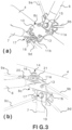
- the Figure 3 represents two partial views (a) and (b) showing a fixing plate 8c fixed to the lower spar 4 of the lattice beam structure.
- the fixing plate 8c therefore replaces, in accordance with the invention, the fixing plate 8c illustrated on the figure 2 .
- the fixing plate 8c comprises a central surface 10 matching the external shape of the spar 4 as well as two flat fins 11a and 11b extending laterally the central surface 10 and extending radially relative to the spar 4, forming between them an angle substantially equal to 90°.
- the fixing plate 8c is secured to the spar preferably by means of four rivets 13 at the level of the central surface 10.
- the first flat fin 11a forms a first fixing surface for the removable fixing of one end of a first crosspiece, here the first side crosspiece 6 of one end of a first tie rod 9a and of one end of a second tie rod 9b.
- the second flat fin 11b forms a second fixing surface for the removable fixing of one end of a second crosspiece, here the second side crosspiece 7, of one end of a third tie rod 9c and of one end of a fourth tie rod 9d among said plurality of tie rods.
- each plane fin 11a and 11b of the fixing plate 8c comprises here, in accordance with the invention, a single fixing orifice, preferably located in its center.
- a single first bolting system 14 comprising a fixing screw 15 passing through the fixing hole of the first flat fin 11a, and a tightening nut 16.
- the end of the second crosspiece 7, the end of the third tie rod 9c and the end of the fourth tie rod 9d are fixed together by a single second bolting system 17 comprising a fixing screw 18 passing through the fixing hole of the second flat fin 11b, and a tightening nut 19.
- the ends of the crosspieces 6 and 7 are preferably fixed on the internal faces of the flat fins 11a and 11b, that is to say the faces of the fins which are opposite each other, while the ends of the tie rods 9a, 9b , 9c, 9d are preferably fixed on the external faces of the plane fins 11a and 11b.
- the ends of the two tie rods which are fixed on the same flat fixing fin are identical, and are conventionally formed by a flattened end piece fixed or integrated at one end of the longitudinal body of the tie rod (see for example the flattened end 20 for the tie rod 9a in Figure 4) pierced with a circular through opening to allow the passage of the screw of the bolting system.
- one end of one of the two tie rods further comprises a clearance compensation device, for example an eccentric washer making it possible to vary the fixing center distance between the two ends of this tie rod.
- the end of the tie rod 9b of a on the other hand, and the tie rod 9d on the other hand comprises such a slack take-up device 21.
- the tie rods whose end does not include a slack take-up device are preferably mounted first, so that their respective end is in contact with the fixing surface formed by the corresponding flat fin.
- the tie rods whose end includes a play take-up device namely the second tie rod 9b and the fourth tie rod 9d of the Figure 3 ) are then mounted above, so that their respective end is in contact with the end of the tie rod mounted first.
- the fixing plate being directly subjected to less effort, it is also possible to reduce its size, more precisely the length of its central surface 10 and of the flat fins 11a, 11b in the longitudinal direction of the spar 4, by half compared to to the fixing plate 8c of the figure 2 . This results in a halving of the weight of each mounting plate used. for mounting truss support beam, which further contributes to a reduction in the overall weight of the truss support beam.
- the lattice support beam comprises equilateral triangular assemblies.
- all the fixing plates fixed to the three spars are identical and each include two flat fins forming an angle between them equal to approximately 60°.
Landscapes
- Life Sciences & Earth Sciences (AREA)
- Sustainable Development (AREA)
- Aiming, Guidance, Guns With A Light Source, Armor, Camouflage, And Targets (AREA)
- Photovoltaic Devices (AREA)
- Aerials With Secondary Devices (AREA)
- Joining Of Building Structures In Genera (AREA)
- Mutual Connection Of Rods And Tubes (AREA)
- Variable-Direction Aerials And Aerial Arrays (AREA)
- Load-Engaging Elements For Cranes (AREA)
- Rod-Shaped Construction Members (AREA)
Claims (9)
- Gitterförmiger Trägerbalken (1) mit dreieckigem Querschnitt, umfassend:- einen Satz von drei Längsträgern (2, 3, 4), die sich parallel entlang einer Haupterstreckungsrichtung des Balkens erstrecken,- eine Vielzahl von Dreiecksverbindungen, die entlang der Haupterstreckungsrichtung verteilt sind und sich jeweils in einer Ebene senkrecht zu der Haupterstreckungsrichtung erstrecken, wobei jede Dreiecksverbindung durch drei Querträger (5, 6, 7) gebildet ist, die die Längsträger paarweise mechanisch miteinander verbinden,- eine Vielzahl von Zugstangen (9, 9a, 9b, 9c, 9d), die jeweils die Längsträger (2, 3, 4) paarweise mechanisch miteinander verbinden, indem sie sich zwischen zwei aufeinanderfolgenden Dreiecksverbindungen erstrecken,- eine Vielzahl von an den Längsträgern befestigten Befestigungsplatten (8a, 8b, 8c), wobei jede an einem bestimmten Längsträger der drei Längsträger befestigte Befestigungsplatte (8a, 8b, 8c) eine erste ebene Rippe (11a) und eine zweite Ebene Rippe (11b) aufweist, die sich radial zu dem bestimmten Längsträger erstreckt, wobei die erste ebene Rippe (11a) eine erste Befestigungsfläche zur lösbaren Befestigung eines Endes eines ersten Querträgers (6) der Vielzahl von Querträgern, eines Endes einer ersten Zugstange (9a) und eines Endes einer zweiten Zugstange (9b) aus der Vielzahl von Zugstangen bildet, und die zweite ebene Rippe (11b) eine zweite Befestigungsfläche zur lösbaren Befestigung eines Endes eines zweiten Querträgers (7) aus der Vielzahl von Querträgern, eines Endes eines dritten Zugstange (9c) und eines Endes einer vierten Zugstange (9d) der Vielzahl von Zugstangen bildet, wobei jede Befestigungsplatte (8a, 8b, 8c) eine mittlere Fläche (10) umfasst, die sich der äußeren Form und dem gegebenen Längsträger anpasst und fest mit dem gegebenen Längsträger verbunden ist, wobei die erste ebene Rippe (11a) und die zweite ebene Rippe (11b) die mittlere Fläche (10) seitlich verlängern, indem sie sich radial in Bezug auf den gegebenen Längsträger erstrecken,dadurch gekennzeichnet, dass das Ende des ersten Querträgers (6), das Ende der ersten Zugstange (9a) und das Ende der zweiten Zugstange (9b) durch ein einziges erstes Verschraubungssystem (14) mit einer Befestigungsschraube (15), die durch dieselbe Befestigungsöffnung der ersten ebenen Rippe (11a) verläuft, aneinander befestigt sind, dass das Ende des zweiten Querträgers (7), das Ende der dritten Zugstange (9c) und das Ende der vierten Zugstange (9d) durch ein einziges zweites Verschraubungssystem (17) mit einer Befestigungsschraube (18), die durch eine gleiche Befestigungsöffnung der zweiten ebenen Rippe (11b) verläuft, aneinander befestigt sind, dass das Ende des ersten Querträgers (6) an einer Innenseite der ersten ebenen Lamelle (11a) befestigt ist, während das Ende des ersten Zugstange (9a) und das Ende des zweiten Zugstange (9b) an einer Außenseite der ersten ebenen Lamelle (11a) befestigt sind, und dass das Ende des zweiten Querträgers (7) an einer Innenseite der zweiten ebenen Lamelle (11b) befestigt ist, während das Ende der dritten Zugstange (9c) und das Ende der vierten Zugstange (9d) an einer Außenseite der zweiten ebenen Rippe (11b) befestigt sind.
- Balken (1) nach Anspruch 1, dadurch gekennzeichnet, dass jede Befestigungsplatte (8a, 8b, 8c) mittels Nieten (13) an der mittleren Fläche (10) fest mit dem gegebenen Längsträger (2, 3, 4) verbunden ist.
- Balken (1) nach einem der vorherigen Ansprüche, dadurch gekennzeichnet, dass das Ende der ersten Zugstange (9a) bzw. der dritten Zugstange (9c) die Außenseite der ersten ebenen Rippe (11a) bzw. die Außenseite der zweiten ebenen Rippe (11b) berührt.
- Balken (1) nach Anspruch 3, dadurch gekennzeichnet, dass das Ende der zweiten Zugstange (9b) bzw. der vierten Zugstange (9d) eine Spielausgleichsvorrichtung (21) umfasst.
- Balken (1) nach einem der vorherigen Ansprüche, dadurch gekennzeichnet, dass die gleiche Befestigungsöffnung der ersten ebenen Rippe (11a) bzw. der zweiten ebenen Rippe (11b) in der Mitte der ersten ebenen Rippe (11a) bzw. der zweiten ebenen Rippe (11b) angeordnet ist.
- Balken (1) nach einem der vorherigen Ansprüche, wobei die Anordnung von drei Längsträgern (2, 3, 4) aus einem unteren Längsträger (4), einem ersten oberen Längsträger (2) und einem zweiten oberen Längsträger (3) besteht, und jede Dreiecksanordnung einen oberen Querträger (5), der den ersten oberen Längsträger (2) mit dem zweiten oberen Längsträger (3) verbindet, einen ersten seitlichen Querträger (6), der den ersten oberen Längsträger (2) mit dem unteren Längsträger (4) verbindet, und einen zweiten Seitlichen Querträger (7), der den zweiten oberen Längsträger (3) mit dem unteren Längsträger (4) verbindet, aufweist, wobei das erste Ende und das zweite Ende von jedem oberen Querträger (5) einer gegebenen Dreiecksanordnung direkt an einer ersten Befestigungsplatte (8a) der Vielzahl von Befestigungsplatten, die an dem ersten oberen Längsträger (2) befestigt ist, bzw. an einer zweiten Befestigungsplatte (8b) der Vielzahl von Befestigungsplatten, die an dem zweiten oberen Längsträger (3) befestigt ist, befestigt sind,das erste Ende und das zweite Ende von jedem ersten seitlichen Querträger (6) der gegebenen dreieckigen Anordnung direkt an der ersten Befestigungsplatte (8a) bzw. an einer dritten Befestigungsplatte (8c) der Vielzahl von Befestigungsplatten, die an dem unteren Längsträger (4) befestigt sind, befestigt sind,und das erste Ende und das zweite Ende von jedem zweiten seitlichen Querträgers (7) der gegebenen dreieckigen Anordnung direkt jeweils an der zweiten Befestigungsplatte (8b) und an der dritten Befestigungsplatte (8c) befestigt sind.
- Balken (1) nach Anspruch 6, dadurch gekennzeichnet, dass die oberen Querträger (5) und der erste und der zweite seitliche Querträger (6, 7) die gleiche Länge aufweisen, sodass gleichseitige Dreiecksverbindungen entstehen, und dass die erste ebene Rippe (11a) und die zweite ebene Rippe (11b) von jeder der ersten, der zweiten und der dritten Befestigungsplatte (8a, 8b, Be) untereinander einen Winkel von im Wesentlichen 60° einschließen.
- Balken (1) nach Anspruch 6, dadurch gekennzeichnet, dass der erste und der zweite seitliche Querträger (6, 7) gleich lang sind, sodass gleichschenklige Dreiecksverbindungen entstehen, dass die erste ebene Rippe (11a) und die zweite ebene Rippe (11b) von jeder der ersten und der zweiten Befestigungsplatte (8a, 8b) untereinander einen Winkel bilden, der im Wesentlichen gleich wie 45° ist, und dass die erste ebene Rippe (11a) und die zweite ebene Rippe (11b) der dritten Befestigungsplatte (8c) untereinander einen Winkel bilden, der im Wesentlichen gleich wie 90° ist.
- Sonnennachführung, dadurch gekennzeichnet, dass sie einen Balken (1) nach einem der Ansprüche 7 oder 8 umfasst, wobei der Balken einen Tisch einer Sonnennachführung trägt, der mit mindestens einer Vorrichtung zum Sammeln von Sonnenenergie ausgestattet ist und auf dem ersten oberen Längsträger (2) und dem zweiten oberen Längsträger (3) aufliegt.
Applications Claiming Priority (2)
| Application Number | Priority Date | Filing Date | Title |
|---|---|---|---|
| FR2003501A FR3109252B1 (fr) | 2020-04-08 | 2020-04-08 | Poutre de soutien en treillis et suiveur solaire comportant une telle poutre |
| PCT/FR2021/050572 WO2021205097A1 (fr) | 2020-04-08 | 2021-04-01 | Poutre de soutien en treillis et suiveur solaire comportant une telle poutre |
Publications (3)
| Publication Number | Publication Date |
|---|---|
| EP4133590A1 EP4133590A1 (de) | 2023-02-15 |
| EP4133590C0 EP4133590C0 (de) | 2024-01-24 |
| EP4133590B1 true EP4133590B1 (de) | 2024-01-24 |
Family
ID=70614332
Family Applications (1)
| Application Number | Title | Priority Date | Filing Date |
|---|---|---|---|
| EP21722273.6A Active EP4133590B1 (de) | 2020-04-08 | 2021-04-01 | Gitterförmiger trägerbalken und sonnenfolger mit einem solchen träger |
Country Status (9)
| Country | Link |
|---|---|
| US (1) | US20230147983A1 (de) |
| EP (1) | EP4133590B1 (de) |
| AU (1) | AU2021252168A1 (de) |
| BR (1) | BR112022020028A2 (de) |
| CA (1) | CA3174355A1 (de) |
| CL (1) | CL2022002753A1 (de) |
| CO (1) | CO2022015293A2 (de) |
| FR (1) | FR3109252B1 (de) |
| WO (1) | WO2021205097A1 (de) |
Families Citing this family (1)
| Publication number | Priority date | Publication date | Assignee | Title |
|---|---|---|---|---|
| CN113756504B (zh) * | 2021-09-30 | 2022-07-01 | 北京建工集团有限责任公司 | 一种带有阳角的直角铝合金网壳的施工方法 |
Family Cites Families (7)
| Publication number | Priority date | Publication date | Assignee | Title |
|---|---|---|---|---|
| US9447990B2 (en) * | 2011-09-29 | 2016-09-20 | Michael Zuritis | Solar array support structure with a telescopic wind brace |
| CN105242372A (zh) * | 2015-10-19 | 2016-01-13 | 中国华能集团清洁能源技术研究院有限公司 | 一种线性菲涅尔太阳能反射镜框架 |
| WO2018121778A1 (zh) * | 2016-12-30 | 2018-07-05 | 江苏中信博新能源科技股份有限公司 | 一种光伏阵列支撑系统 |
| CN206506474U (zh) * | 2017-02-07 | 2017-09-19 | 江苏中信博新能源科技股份有限公司 | 一种预装太阳能板桁架 |
| CN106788182A (zh) * | 2016-12-30 | 2017-05-31 | 江苏中信博新能源科技股份有限公司 | 一种光伏跟踪系统 |
| ES2765414T3 (es) | 2017-02-17 | 2020-06-09 | Nexans Solar Tech | Seguidor solar con acoplamiento cinemático |
| CN107026604A (zh) * | 2017-04-18 | 2017-08-08 | 苏州聚晟太阳能科技股份有限公司 | 长跨距跟踪支架 |
-
2020
- 2020-04-08 FR FR2003501A patent/FR3109252B1/fr not_active Expired - Fee Related
-
2021
- 2021-04-01 EP EP21722273.6A patent/EP4133590B1/de active Active
- 2021-04-01 AU AU2021252168A patent/AU2021252168A1/en not_active Abandoned
- 2021-04-01 CA CA3174355A patent/CA3174355A1/en active Pending
- 2021-04-01 WO PCT/FR2021/050572 patent/WO2021205097A1/fr not_active Ceased
- 2021-04-01 BR BR112022020028A patent/BR112022020028A2/pt unknown
- 2021-04-01 US US17/915,433 patent/US20230147983A1/en not_active Abandoned
-
2022
- 2022-10-06 CL CL2022002753A patent/CL2022002753A1/es unknown
- 2022-10-27 CO CONC2022/0015293A patent/CO2022015293A2/es unknown
Also Published As
| Publication number | Publication date |
|---|---|
| EP4133590C0 (de) | 2024-01-24 |
| WO2021205097A1 (fr) | 2021-10-14 |
| US20230147983A1 (en) | 2023-05-11 |
| CL2022002753A1 (es) | 2023-09-15 |
| FR3109252A1 (fr) | 2021-10-15 |
| CO2022015293A2 (es) | 2023-01-26 |
| EP4133590A1 (de) | 2023-02-15 |
| FR3109252B1 (fr) | 2022-04-22 |
| AU2021252168A1 (en) | 2022-10-27 |
| BR112022020028A2 (pt) | 2022-11-22 |
| CA3174355A1 (en) | 2021-10-14 |
Similar Documents
| Publication | Publication Date | Title |
|---|---|---|
| EP2121434B1 (de) | Flugzeugflügel mit mehreren abnehmbaren elementen | |
| EP3501098B1 (de) | Sonnennachführer | |
| WO2011036386A1 (fr) | Ensemble d'aeronef comprenant un element d'accrochage d'un moteur et aeronef associe | |
| EP2388829A1 (de) | Tragestrukturmodul für Fotovoltaikpaneele, Tragestruktur, die solche Module umfasst, und Montageverfahren einer solchen Struktur | |
| EP3542203B1 (de) | Reflektor mit verbessertem design und dessen herstellungsverfahren für das gebiet der sonnenenergie | |
| EP4133590A1 (de) | Gitterförmiger trägerbalken und sonnenfolger mit einem solchen träger | |
| EP2197739B1 (de) | Flugzeugrumpfstruktur, aus verbundmaterial hergestellter rumpf und mit einer solchen rumpfstruktur ausgerüstetes flugzeug | |
| FR3103982A1 (fr) | Poutre de soutien en treillis et suiveur solaire comportant une telle poutre | |
| EP1741943B1 (de) | Lageranordnung zur Kraftübertragung einer Windenergieanlage | |
| CA3068214C (fr) | Troncon de mat d'eolienne, mat d'eolienne et procede d'assemblage | |
| EP2602570A2 (de) | Trägerstruktur für ein Parabolelement eines Solarkollektors | |
| FR2946712A1 (fr) | Bielle pour la construction aeronautique et procede de fabrication d'une telle bielle | |
| FR3058126A1 (fr) | Faisceau torsible pour pale, un ensemble de faisceaux torsibles, un rotor et un aeronef | |
| EP4570647A1 (de) | Vorrichtung zur absorption von energie durch kompression, luftfahrzeug, das mindestens eine solche vorrichtung umfasst | |
| CA3118471C (fr) | Troncon de mat d'eolienne, mat d'eolienne et procede d'assemblage | |
| EP4570648A1 (de) | Flugzeug mit mindestens einer abnehmbaren druckenergieabsorptionsvorrichtung | |
| EP1548233B1 (de) | Befestigungsvorrichtung für Statorschaufel, sowie Leitschaufelstufe eines Verdichters mit einer solchen Vorrichtung | |
| US20160146187A1 (en) | Hub for a wind turbine | |
| FR3098889A1 (fr) | Structure en treillis pliable, notamment pour suiveur solaire | |
| WO2021009425A1 (fr) | Tirant pour structure notamment en treillis | |
| EP3536605B1 (de) | Torsionskasten für luftfahrzeuge, der aus paarweise zusammengeschweissten elementen gebildet wird, und sein herstellungsverfahren | |
| FR3043151A1 (fr) | Systeme de liaison bout a bout entre deux poutres et son application aux installations solaires lineaires | |
| FR3079884A1 (fr) | Eolienne construite a partir de deux eoliennes a axe horizontal comprenant un systeme de voiles mobiles | |
| BE536596A (de) | ||
| WO2011006805A2 (fr) | Procédé de réalisation de liaisons mécaniques |
Legal Events
| Date | Code | Title | Description |
|---|---|---|---|
| STAA | Information on the status of an ep patent application or granted ep patent |
Free format text: STATUS: UNKNOWN |
|
| STAA | Information on the status of an ep patent application or granted ep patent |
Free format text: STATUS: THE INTERNATIONAL PUBLICATION HAS BEEN MADE |
|
| PUAI | Public reference made under article 153(3) epc to a published international application that has entered the european phase |
Free format text: ORIGINAL CODE: 0009012 |
|
| STAA | Information on the status of an ep patent application or granted ep patent |
Free format text: STATUS: REQUEST FOR EXAMINATION WAS MADE |
|
| 17P | Request for examination filed |
Effective date: 20221108 |
|
| AK | Designated contracting states |
Kind code of ref document: A1 Designated state(s): AL AT BE BG CH CY CZ DE DK EE ES FI FR GB GR HR HU IE IS IT LI LT LU LV MC MK MT NL NO PL PT RO RS SE SI SK SM TR |
|
| DAV | Request for validation of the european patent (deleted) | ||
| DAX | Request for extension of the european patent (deleted) | ||
| GRAP | Despatch of communication of intention to grant a patent |
Free format text: ORIGINAL CODE: EPIDOSNIGR1 |
|
| STAA | Information on the status of an ep patent application or granted ep patent |
Free format text: STATUS: GRANT OF PATENT IS INTENDED |
|
| INTG | Intention to grant announced |
Effective date: 20230817 |
|
| GRAS | Grant fee paid |
Free format text: ORIGINAL CODE: EPIDOSNIGR3 |
|
| GRAA | (expected) grant |
Free format text: ORIGINAL CODE: 0009210 |
|
| STAA | Information on the status of an ep patent application or granted ep patent |
Free format text: STATUS: THE PATENT HAS BEEN GRANTED |
|
| AK | Designated contracting states |
Kind code of ref document: B1 Designated state(s): AL AT BE BG CH CY CZ DE DK EE ES FI FR GB GR HR HU IE IS IT LI LT LU LV MC MK MT NL NO PL PT RO RS SE SI SK SM TR |
|
| REG | Reference to a national code |
Ref country code: GB Ref legal event code: FG4D Free format text: NOT ENGLISH |
|
| REG | Reference to a national code |
Ref country code: CH Ref legal event code: EP |
|
| REG | Reference to a national code |
Ref country code: IE Ref legal event code: FG4D Free format text: LANGUAGE OF EP DOCUMENT: FRENCH |
|
| REG | Reference to a national code |
Ref country code: DE Ref legal event code: R096 Ref document number: 602021008772 Country of ref document: DE |
|
| U01 | Request for unitary effect filed |
Effective date: 20240219 |
|
| U07 | Unitary effect registered |
Designated state(s): AT BE BG DE DK EE FI FR IT LT LU LV MT NL PT SE SI Effective date: 20240228 |
|
| REG | Reference to a national code |
Ref country code: LT Ref legal event code: MG9D |
|
| U20 | Renewal fee for the european patent with unitary effect paid |
Year of fee payment: 4 Effective date: 20240424 |
|
| PG25 | Lapsed in a contracting state [announced via postgrant information from national office to epo] |
Ref country code: IS Free format text: LAPSE BECAUSE OF FAILURE TO SUBMIT A TRANSLATION OF THE DESCRIPTION OR TO PAY THE FEE WITHIN THE PRESCRIBED TIME-LIMIT Effective date: 20240524 |
|
| PG25 | Lapsed in a contracting state [announced via postgrant information from national office to epo] |
Ref country code: GR Free format text: LAPSE BECAUSE OF FAILURE TO SUBMIT A TRANSLATION OF THE DESCRIPTION OR TO PAY THE FEE WITHIN THE PRESCRIBED TIME-LIMIT Effective date: 20240425 |
|
| PG25 | Lapsed in a contracting state [announced via postgrant information from national office to epo] |
Ref country code: HR Free format text: LAPSE BECAUSE OF FAILURE TO SUBMIT A TRANSLATION OF THE DESCRIPTION OR TO PAY THE FEE WITHIN THE PRESCRIBED TIME-LIMIT Effective date: 20240124 Ref country code: RS Free format text: LAPSE BECAUSE OF FAILURE TO SUBMIT A TRANSLATION OF THE DESCRIPTION OR TO PAY THE FEE WITHIN THE PRESCRIBED TIME-LIMIT Effective date: 20240424 |
|
| PG25 | Lapsed in a contracting state [announced via postgrant information from national office to epo] |
Ref country code: ES Free format text: LAPSE BECAUSE OF FAILURE TO SUBMIT A TRANSLATION OF THE DESCRIPTION OR TO PAY THE FEE WITHIN THE PRESCRIBED TIME-LIMIT Effective date: 20240124 |
|
| PG25 | Lapsed in a contracting state [announced via postgrant information from national office to epo] |
Ref country code: RS Free format text: LAPSE BECAUSE OF FAILURE TO SUBMIT A TRANSLATION OF THE DESCRIPTION OR TO PAY THE FEE WITHIN THE PRESCRIBED TIME-LIMIT Effective date: 20240424 Ref country code: NO Free format text: LAPSE BECAUSE OF FAILURE TO SUBMIT A TRANSLATION OF THE DESCRIPTION OR TO PAY THE FEE WITHIN THE PRESCRIBED TIME-LIMIT Effective date: 20240424 Ref country code: IS Free format text: LAPSE BECAUSE OF FAILURE TO SUBMIT A TRANSLATION OF THE DESCRIPTION OR TO PAY THE FEE WITHIN THE PRESCRIBED TIME-LIMIT Effective date: 20240524 Ref country code: HR Free format text: LAPSE BECAUSE OF FAILURE TO SUBMIT A TRANSLATION OF THE DESCRIPTION OR TO PAY THE FEE WITHIN THE PRESCRIBED TIME-LIMIT Effective date: 20240124 Ref country code: GR Free format text: LAPSE BECAUSE OF FAILURE TO SUBMIT A TRANSLATION OF THE DESCRIPTION OR TO PAY THE FEE WITHIN THE PRESCRIBED TIME-LIMIT Effective date: 20240425 Ref country code: ES Free format text: LAPSE BECAUSE OF FAILURE TO SUBMIT A TRANSLATION OF THE DESCRIPTION OR TO PAY THE FEE WITHIN THE PRESCRIBED TIME-LIMIT Effective date: 20240124 |
|
| PG25 | Lapsed in a contracting state [announced via postgrant information from national office to epo] |
Ref country code: PL Free format text: LAPSE BECAUSE OF FAILURE TO SUBMIT A TRANSLATION OF THE DESCRIPTION OR TO PAY THE FEE WITHIN THE PRESCRIBED TIME-LIMIT Effective date: 20240124 |
|
| PG25 | Lapsed in a contracting state [announced via postgrant information from national office to epo] |
Ref country code: PL Free format text: LAPSE BECAUSE OF FAILURE TO SUBMIT A TRANSLATION OF THE DESCRIPTION OR TO PAY THE FEE WITHIN THE PRESCRIBED TIME-LIMIT Effective date: 20240124 |
|
| PG25 | Lapsed in a contracting state [announced via postgrant information from national office to epo] |
Ref country code: SM Free format text: LAPSE BECAUSE OF FAILURE TO SUBMIT A TRANSLATION OF THE DESCRIPTION OR TO PAY THE FEE WITHIN THE PRESCRIBED TIME-LIMIT Effective date: 20240124 |
|
| PG25 | Lapsed in a contracting state [announced via postgrant information from national office to epo] |
Ref country code: CZ Free format text: LAPSE BECAUSE OF FAILURE TO SUBMIT A TRANSLATION OF THE DESCRIPTION OR TO PAY THE FEE WITHIN THE PRESCRIBED TIME-LIMIT Effective date: 20240124 |
|
| REG | Reference to a national code |
Ref country code: DE Ref legal event code: R097 Ref document number: 602021008772 Country of ref document: DE |
|
| PG25 | Lapsed in a contracting state [announced via postgrant information from national office to epo] |
Ref country code: SK Free format text: LAPSE BECAUSE OF FAILURE TO SUBMIT A TRANSLATION OF THE DESCRIPTION OR TO PAY THE FEE WITHIN THE PRESCRIBED TIME-LIMIT Effective date: 20240124 |
|
| PG25 | Lapsed in a contracting state [announced via postgrant information from national office to epo] |
Ref country code: SM Free format text: LAPSE BECAUSE OF FAILURE TO SUBMIT A TRANSLATION OF THE DESCRIPTION OR TO PAY THE FEE WITHIN THE PRESCRIBED TIME-LIMIT Effective date: 20240124 Ref country code: SK Free format text: LAPSE BECAUSE OF FAILURE TO SUBMIT A TRANSLATION OF THE DESCRIPTION OR TO PAY THE FEE WITHIN THE PRESCRIBED TIME-LIMIT Effective date: 20240124 Ref country code: CZ Free format text: LAPSE BECAUSE OF FAILURE TO SUBMIT A TRANSLATION OF THE DESCRIPTION OR TO PAY THE FEE WITHIN THE PRESCRIBED TIME-LIMIT Effective date: 20240124 |
|
| PG25 | Lapsed in a contracting state [announced via postgrant information from national office to epo] |
Ref country code: MC Free format text: LAPSE BECAUSE OF FAILURE TO SUBMIT A TRANSLATION OF THE DESCRIPTION OR TO PAY THE FEE WITHIN THE PRESCRIBED TIME-LIMIT Effective date: 20240124 |
|
| PG25 | Lapsed in a contracting state [announced via postgrant information from national office to epo] |
Ref country code: MC Free format text: LAPSE BECAUSE OF FAILURE TO SUBMIT A TRANSLATION OF THE DESCRIPTION OR TO PAY THE FEE WITHIN THE PRESCRIBED TIME-LIMIT Effective date: 20240124 |
|
| PLBE | No opposition filed within time limit |
Free format text: ORIGINAL CODE: 0009261 |
|
| REG | Reference to a national code |
Ref country code: CH Ref legal event code: PL |
|
| STAA | Information on the status of an ep patent application or granted ep patent |
Free format text: STATUS: NO OPPOSITION FILED WITHIN TIME LIMIT |
|
| 26N | No opposition filed |
Effective date: 20241025 |
|
| PG25 | Lapsed in a contracting state [announced via postgrant information from national office to epo] |
Ref country code: CH Free format text: LAPSE BECAUSE OF NON-PAYMENT OF DUE FEES Effective date: 20240430 |
|
| PG25 | Lapsed in a contracting state [announced via postgrant information from national office to epo] |
Ref country code: IE Free format text: LAPSE BECAUSE OF NON-PAYMENT OF DUE FEES Effective date: 20240401 |
|
| PG25 | Lapsed in a contracting state [announced via postgrant information from national office to epo] |
Ref country code: RO Free format text: LAPSE BECAUSE OF FAILURE TO SUBMIT A TRANSLATION OF THE DESCRIPTION OR TO PAY THE FEE WITHIN THE PRESCRIBED TIME-LIMIT Effective date: 20240124 |
|
| PG25 | Lapsed in a contracting state [announced via postgrant information from national office to epo] |
Ref country code: CY Free format text: LAPSE BECAUSE OF FAILURE TO SUBMIT A TRANSLATION OF THE DESCRIPTION OR TO PAY THE FEE WITHIN THE PRESCRIBED TIME-LIMIT; INVALID AB INITIO Effective date: 20210401 |
|
| PG25 | Lapsed in a contracting state [announced via postgrant information from national office to epo] |
Ref country code: HU Free format text: LAPSE BECAUSE OF FAILURE TO SUBMIT A TRANSLATION OF THE DESCRIPTION OR TO PAY THE FEE WITHIN THE PRESCRIBED TIME-LIMIT; INVALID AB INITIO Effective date: 20210401 |
|
| PG25 | Lapsed in a contracting state [announced via postgrant information from national office to epo] |
Ref country code: TR Free format text: LAPSE BECAUSE OF FAILURE TO SUBMIT A TRANSLATION OF THE DESCRIPTION OR TO PAY THE FEE WITHIN THE PRESCRIBED TIME-LIMIT Effective date: 20240124 |
|
| U90 | Renewal fees not paid: noting of loss of rights |
Free format text: RENEWAL FEE NOT PAID FOR YEAR 05 Effective date: 20251117 |
|
| GBPC | Gb: european patent ceased through non-payment of renewal fee |
Effective date: 20250401 |
|
| PG25 | Lapsed in a contracting state [announced via postgrant information from national office to epo] |
Ref country code: GB Free format text: LAPSE BECAUSE OF NON-PAYMENT OF DUE FEES Effective date: 20250401 |
|
| U93 | Unitary patent lapsed |
Free format text: RENEWAL FEE NOT PAID Effective date: 20250430 |