EP4133343B1 - Procédé de fonctionnement d'un système d'automatisation redondant et système d'automatisation redondant - Google Patents
Procédé de fonctionnement d'un système d'automatisation redondant et système d'automatisation redondant Download PDFInfo
- Publication number
- EP4133343B1 EP4133343B1 EP21731050.7A EP21731050A EP4133343B1 EP 4133343 B1 EP4133343 B1 EP 4133343B1 EP 21731050 A EP21731050 A EP 21731050A EP 4133343 B1 EP4133343 B1 EP 4133343B1
- Authority
- EP
- European Patent Office
- Prior art keywords
- subsystem
- output
- output data
- acknowledgement
- dev
- Prior art date
- Legal status (The legal status is an assumption and is not a legal conclusion. Google has not performed a legal analysis and makes no representation as to the accuracy of the status listed.)
- Active
Links
- 238000000034 method Methods 0.000 title claims description 41
- 230000006854 communication Effects 0.000 claims description 39
- 238000004891 communication Methods 0.000 claims description 38
- 230000008569 process Effects 0.000 claims description 24
- 230000002093 peripheral effect Effects 0.000 claims description 8
- 230000009471 action Effects 0.000 claims description 5
- 238000001514 detection method Methods 0.000 claims description 4
- 238000012546 transfer Methods 0.000 claims description 4
- 230000008901 benefit Effects 0.000 description 9
- 230000004913 activation Effects 0.000 description 5
- 238000005516 engineering process Methods 0.000 description 3
- 238000004519 manufacturing process Methods 0.000 description 3
- 238000012545 processing Methods 0.000 description 3
- 230000005540 biological transmission Effects 0.000 description 2
- 238000004092 self-diagnosis Methods 0.000 description 2
- 230000001360 synchronised effect Effects 0.000 description 2
- 238000013459 approach Methods 0.000 description 1
- 238000013461 design Methods 0.000 description 1
- 238000011161 development Methods 0.000 description 1
- 238000010586 diagram Methods 0.000 description 1
- 230000000694 effects Effects 0.000 description 1
- 230000007257 malfunction Effects 0.000 description 1
- 238000004886 process control Methods 0.000 description 1
- 230000004044 response Effects 0.000 description 1
Images


Classifications
-
- G—PHYSICS
- G05—CONTROLLING; REGULATING
- G05B—CONTROL OR REGULATING SYSTEMS IN GENERAL; FUNCTIONAL ELEMENTS OF SUCH SYSTEMS; MONITORING OR TESTING ARRANGEMENTS FOR SUCH SYSTEMS OR ELEMENTS
- G05B19/00—Programme-control systems
- G05B19/02—Programme-control systems electric
- G05B19/04—Programme control other than numerical control, i.e. in sequence controllers or logic controllers
- G05B19/042—Programme control other than numerical control, i.e. in sequence controllers or logic controllers using digital processors
- G05B19/0428—Safety, monitoring
-
- G—PHYSICS
- G05—CONTROLLING; REGULATING
- G05B—CONTROL OR REGULATING SYSTEMS IN GENERAL; FUNCTIONAL ELEMENTS OF SUCH SYSTEMS; MONITORING OR TESTING ARRANGEMENTS FOR SUCH SYSTEMS OR ELEMENTS
- G05B2219/00—Program-control systems
- G05B2219/20—Pc systems
- G05B2219/24—Pc safety
- G05B2219/24024—Safety, surveillance
Definitions
- the invention relates to a method for operating a redundant automation system for controlling a technical process, wherein a first subsystem, a second subsystem, a third subsystem and output means for the process are operated in a communication network in such a way that communication paths between them are used for exchange of data are used, wherein the first subsystem with a first control program with a first program cycle forwards first output data to the output means in a cycle-oriented manner via a peripheral protocol, for which an active first application relationship is set up between the first subsystem and the output means, in parallel with the first subsystem second subsystem with a control program with a second program cycle second output data or the third subsystem with a third control program with a third program cycle calculates third output data in readiness to take over control of the technical process, wherein a passive second application relationship continues to exist between the second subsystem and the output means and a passive third application relationship is established between the third subsystem and the output means, the three subsystems being operated in such a way that they have mutual knowledge of their calculated output data.
- H systems highly available solutions
- Developing such highly available solutions is very cost-intensive, although an H system that is usually used in the automation environment is characterized by the fact that two or more subsystems in the form of automation devices or computer systems are coupled to each other via a synchronization connection. In principle, both subsystems can read and/write access to the peripheral units connected to this H system.
- One of the two subsystems is the leader in terms of the peripherals connected to the system. This means that outputs to peripheral units or output information or output data for these peripheral units are only carried out by one of the two subsystems, which also works as a master or has taken on a master function.
- both subsystems can run synchronously, they are usually synchronized at regular intervals via synchronization connections.
- different forms can be distinguished, e.g. a warm standby or a hot standby.
- the two subsystems must have the same system state at the time of failure. This is ensured by a suitable synchronization procedure.
- EP 2 657 797 B1 discloses a similar method, in which interruption points are transmitted to the slave at a certain point in time after an event occurs.
- the task is solved in that the second subsystem has a second output receipt and the third subsystem has one sends the third output acknowledgment to the first subsystem, and the first subsystem only passes on the first output data to the output means when the second output acknowledgment and the third output acknowledgment have arrived in the first subsystem, with a comparison means continuing to be operated cyclically in each subsystem, which the first, second and third output data are compared with one another and the respective comparison means are operated in such a way that no further action is carried out in each comparison in which all output data are the same as a result, and in the case of a comparison in which deviations between the output data are determined, that subsystem is recognized as disturbed by means of a majority decision, in which the deviation of the own output data from the other output data is greatest, and based on this result, in the event that the first subsystem was recognized as disturbed, the second application relationship is changed from the passive state in is transferred to an active state and accordingly the first application relationship is transferred from the active state to a passive state and from now on, the second output data is
- the redundant automation system is operated in such a way that the second and third subsystems lag behind the first subsystem and the first subsystem carries out the exchange of data to the other subsystems asynchronously via the communication paths, with a first subsystem consisting of the first subsystem and the second subsystem Tracking system and a second tracking system is formed from the first subsystem and the third subsystem, wherein synchronization data for the first tracking system and the second tracking system are identical and are sent out from the first subsystem via multicast-based communication.
- the two trailing subsystems synchronize asynchronously, with the first subsystem sending the synchronization data to the second subsystem and the third subsystem.
- This has the advantage that the synchronization data for the first tracking system and for the second tracking system are identical and the synchronization data can therefore be transmitted efficiently via multicast-based communication from the first subsystem, which in turn saves the bandwidth in the communication channels.
- the second subsystem sends a second cycle acknowledgment and the third subsystem sends a third cycle acknowledgment to the first subsystem, and in the first subsystem a new first program cycle is only started when all acknowledgments have arrived.
- a processing performance of the first subsystem is decoupled from a communication bandwidth available for event synchronization, which is particularly advantageous with regard to an increasing imbalance between an increase in the processing performance of the process on the one hand and an increase in the communication performance of communication processes.
- Communication between the subsystems and the output means is advantageously configured for a Profinet network with a corresponding peripheral protocol (Profinet system redundancy).
- an outstanding advantage of the method is that at least one subsystem in an IT infrastructure is provided as a virtual subsystem in the form of a service.
- cloud computing The provision of a service in an IT infrastructure is referred to as so-called cloud computing, which usually includes the provision of storage space, computing power and/or application software as a service.
- cloud computing describes the approach of making IT infrastructure available via a computer network without this infrastructure or hardware having to be installed locally on site.
- a third subsystem or a third PLC/PLC can be instantiated cost-effectively in a cloud environment. This makes it possible to implement high-performance, cloud-based automation solutions that offer availability appropriate to the automation environment.
- Another advantage of the solution described here is that you can switch from a "1 of 2" to a “2 of 3" solution during operation to increase reliability for critical process steps.
- a further method step provides that in the event that from now on the second subsystem forwards the output data via the active second application relationship to the output means, the third subsystem now sends the third output acknowledgment and the third cycle acknowledgment to the second subsystem and the second subsystem sends the The second output data is only passed on to the output means when the third output acknowledgment and the third cycle acknowledgment have arrived at the second subsystem.
- the invention also relates to a redundant automation system for controlling a technical process, comprising a first subsystem, a second subsystem, a third subsystem and output means, which are connected via a communication network, the first subsystem being designed with a first control program first program cycle to output first output data to the output means via an active first application relationship in a cycle-oriented manner, the second subsystem is designed with a second control program with a second program cycle, in readiness via a second application relationship To provide output data for the output means, the third subsystem is designed with a third control program with a third program cycle, in readiness to provide third output data for the output means via a third application relationship, wherein the three subsystems are further designed to provide each other with their calculated output data.
- the second subsystem has a second receipt issuing means, which is designed to send a second issuing receipt and the third subsystem has a third receipt issuing means, which is designed to send a third output receipt and the first subsystem has an activation means which is designed to only pass on the first output data to the output means when the second output receipt and the third output receipt have arrived in the first subsystem, and furthermore each subsystem has a comparison means which is designed to cyclically compare the first, second and third output data with one another and in the event that in a comparison in which all output data are the same as a result, no further action is carried out, and in the event that in a comparison, in in which deviations between the output data are determined, that subsystem is recognized as faulty by means of a majority decision in which the deviation of its own output data from the other output data is greatest, a deviation detection means being present for this purpose, the first subsystem being further designed for In the event that the first subsystem has been recognized as disturbed,
- a further advantageous embodiment of the redundant automation system provides that a first tracking system is formed from the first subsystem and the second subsystem, and that a second tracking system is formed from the first subsystem and the third subsystem, the first subsystem being designed in such a way that it provides synchronization data for the first tracking system and the second tracking system via multicast-based communication.
- a further development of the automation system provides that the second receipt issuing means is additionally designed to send a second cycle receipt to the first subsystem and the third receipt issuing means is designed to send a third cycle receipt to the first subsystem and the first subsystem is designed to send a new first one Only start the program cycle when all receipts have been received.
- a cloud is, in particular, an infrastructure that is made available, for example, via the Internet and which usually provides storage space, computing power and/or application software without the corresponding infrastructure having to be installed and stored on a local computer.
- the hardware is usually not operated or provided by the user of an application themselves.
- a cloud or cloud computing can in particular be understood as the provision of IT infrastructure as a service, possibly from a remote location.
- a cloud can be accessible via the Internet, or from A company can be operated as a so-called private cloud, in which the IT infrastructure can be accessed via a network, e.g. a company intranet.
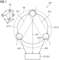
- the redundant automation system 100 includes a first subsystem 1, a second subsystem 2, a third subsystem 3 and output means IO-Dev.
- the subsystems 1, 2, 3 mentioned and the output means IO-Dev are connected via a communication network KN; shown on the side is a symbolized communication network in a structure that is common today, for example for the Internet.
- This communication network KN can be spanned between the subsystems 1,2,3 communication paths KP12, KP13, KP23.
- the first subsystem 1 is designed as a master and accordingly the first subsystem 1 with a first control program P1 with a first program cycle Z1 can output first output data A1 in a cycle-oriented manner via an active first application relationship AR1 to the output means IO-Dev.
- the second subsystem 2 is designed with a second control program P2 with a second program cycle Z2 and is on standby, namely in a slave function, to provide second output data A2 for the output means IO-Dev via a second application relationship AR2.
- the third subsystem 3 is designed with a third control program P3 with a third program cycle Z3 and is also ready to provide third output data A3 for the output means IO-Dev via a third application relationship AR3, the three subsystems 1, 2, 3 also being designed to To provide each other with their calculated output data A1, A2, A3 via the communication paths KP12, KP13, KP23.
- the second and third subsystems 2, 3 follow the first subsystem 1 in time and the first subsystem 1 exchanges the required data asynchronously via the communication paths KP12, KP13, with the first subsystem 1 and the second subsystem 2 forming a first tracking system N12 and a second tracking system N13 is formed from the first subsystem 1 and the third subsystem 3, the necessary synchronization data for the first tracking system N12 and the second tracking system N13 are identical and therefore advantageously only have to be sent once via multicast-based communication from the first subsystem 1 to the other subsystems 2,3.
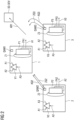
- the first subsystem 1 has a first acknowledgment output means QAM1, via this acknowledgment output means QAM1 the first control program P1 can provide acknowledgments for other subsystems 2, 3 with its first program cycle Z1, for example if the first program cycle Z1 has been completed completely or the first output data A1 is completely available .
- the first control program P1 writes the first output data A1 into a first process image PA1, from which they can be sent from the first process image PA1 via a first application relationship AR1 to an output means IO-Dev.
- the second subsystem 2 and the third subsystem 3 each send their second output acknowledgment AQ2 and their third output acknowledgment AQ3 via the second acknowledgment output means QAM2 or the third receipt issuing means QAM3 to the first subsystem 1.
- the first subsystem 1 has an activation means FSM, which is designed to only pass on the first output data A1 to the output means IO-Dev when the second output acknowledgment AQ2 and the third output acknowledgment AQ3 have arrived in the first subsystem 1.
- FSM activation means
- each subsystem 1,2,3 according to FIG 2 a comparison means V1, V2, V3, which is designed to cyclically compare the first, second and third output data A1, A2, A3 with one another and in the event that in a comparison in which all Output data A1,A2,A3 are the same, no further action is carried out.
- a deviation detection means AEM is available, as described in FIG 3 is shown.
- the deviation detection means AEM is arranged in the first comparison means V1, which provides a deviation frequency AH, based on a subsystem 1, 2, 3, by means of a majority decision ME.
- the first column shows the subsystems 1, 2, 3 as they produce their output data A1, A2, A3.
- the second column should show the value of standardized output data A1, A2, A3.
- the difference between the original data A1, A2, A3 is shown in terms of amounts.
- the difference between the first output data A1 and A2 the difference between the first output data A1 and the third output data A3 and the difference between the second output data A2 and the third output data A3 are therefore represented in terms of amounts.
- the deviation is 1.0 because there is no deviation between the second output data A2 and the third output data A3, based on the first output data A1.
- the second line T2 shows the deviation 1,-,1.
- the third line shows the deviation -.0.1. This results in a deviation frequency AH in the second line for the second subsystem 2, because a deviation of 1 exists twice, which in total gives a value of 2. This means that, based on the majority decision ME, it is determined that the second subsystem 2 must be considered disturbed. Now program scenarios would occur to switch off the faulty subsystem, although the first subsystem 1 still has the master functionality, but the second subsystem 2 is switched off in such a way that it cannot function as a redundant subsystem if the first subsystem 1 fails, now only the third subsystem could 3 act as a redundant subsystem to the failed first subsystem 1.
- the deviation frequency AH would be found in the first line T1 of the first subsystem 1.
- the possibility is shown of arranging at least one subsystem 1, 2, 3, namely the third subsystem 3, in an IT infrastructure as a virtual subsystem in the form of a service.
- the IT infrastructure therefore corresponds to a Cloud C.
- the communication paths KP13 and KP23 can still be set up to the other subsystems 1,2 via an Internet Int.
- the first subsystem 1 and the second subsystem 2 are located in a local area network Lan, such as exists on a production site of an industrial automation system.
- the advantage is that a redundant automation system 100 is set up here, in which a third one is not necessarily required physical subsystem 3 must be placed on the production site, but is implemented as a backup solution in a cloud C, which offers a cost advantage and therefore the third subsystem 3 would not differ from the second subsystem 2.
- the activation means FSM is shown again in relation to the receipts.
- the second output acknowledgment AQ2, the third output acknowledgment AQ3, the second cycle acknowledgment ZQ2 and the third cycle acknowledgment ZQ3 are interconnected via an AND operation and forwarded to the activation means FSM as a validity signal, the first output data A1 provided by the first process image PA1 of the first subsystem 1 can thus be sent to the output means IO-Dev via the first application relationship AR1, for example via a Profinet.
Claims (9)
- Procédé pour faire fonctionner un système (100) d'automatisation redondant pour la commande d'un processus technique, dans lequel on fait fonctionner un premier système (1) partiel, un deuxième système (2) partiel, un troisième système (3) partiel et des moyens (IO-Dev) d'édition pour le processus dans un réseau (KN) de communication, de manière à utiliser des chemins (KP12, KP13, KP23) de communication entre eux pour l'échange de données, dans lequel- le premier système (1) partiel envoie aux moyens (IO-Dev) d'édition par un protocole (PN) périphérique des premières données (A1) de sortie à orientation cycle par un premier programme (P1) de commande ayant un premier cycle (Z1) de programme, dans lequel à cet effet on établit une première relation (AR1) d'application active entre le premier système (1) partiel et les moyens (IO-Dev) d'édition, dans lequel en parallèle au premier système (1) partiel- le deuxième système (2) partiel calcule, pour la préparation de la prise en charge de la commande du processus technique, par un deuxième programme (P2) de commande ayant un deuxième cycle (Z2) de programme des deuxièmes données (A2) de sortie et respectivement le troisième système (3) partiel par un troisième programme (P3) de commande ayant un troisième cycle (Z3) de programme des troisièmes données (A3) de sortie, dans lequel en outre- on établit, entre le deuxième système (2) partiel et les moyens (IO-Dev) d'édition, une deuxième relation (AR2) d'application passive et, entre le troisième système (3) partiel et les moyens (IO-Dev) d'édition, une troisième relation (AR3) d'application passive,- dans lequel on fait fonctionner les trois systèmes (1, 2, 3) partiels, de manière à ce qu'ils aient connaissance l'un l'autre de leurs données (A1, A2, A3) de sortie calculées, caractérisé en ce que- le deuxième système (2) partiel envoie un deuxième accusé (AQ2) de réception et le troisième système (3) partiel envoie un troisième accusé (AQ3) de réception au premier système (1) partiel,- le premier système (1) partiel n'envoie les premières données (A1) de sortie aux moyens (IO-Dev) d'émission que si- le deuxième accusé (AQ2) de réception et le troisième accusé (AQ3) de réception sont arrivés dans le premier système (1) partiel et en outre,- on fait fonctionner cycliquement dans chaque système (1, 2, 3) partiel un moyen (V1, V2, V3) de comparaison, qui compare entre elles les premières, deuxièmes et troisièmes données (A1, A2, A3) de sortie et on fait fonctionner les moyens (V1, V2, V3) respectifs de comparaison, de manière- à ne pas effectuer d'autres actions à chaque comparaison, pour laquelle en résultat toutes les données (A1, A2, A3) de sortie sont les mêmes, et- à détecter pour une comparaison, dans laquelle on constate des écarts entre les données de sortie, comme perturbé le système (1, 2, 3) partiel au moyen d'une décision (ME) à la majorité, dans lequel les écarts de ses propres données (A1, A2, A3) de sortie par rapport aux autres données (A1, A2, A3) de sortie est le plus grand et sur la base de ce résultat,- dans le cas où le premier système (1) partiel a été détecté comme perturbé, on fait passer la deuxième relation (AR2) d'application de l'état passif à un état actif et, d'une manière correspondante, on fait passer la première relation (AR1) d'application de l'état actif à un état passif, et à partir de là, on met les deuxièmes données (A2) de sortie à disposition du processus par les moyens (IO-Device) d'édition, dans lequel le deuxième et le troisième systèmes (2, 3) partiels suivent dans le temps le premier système (1) partiel et le premier système (1) partiel effectue l'échange des données, de manière asynchrone dans le temps par les chemins (KP12, KP13) de communication, dans lequel on forme à partir du premier système (1) partiel et du deuxième système (2) partiel, un premier système (N12) de poursuite, à partir du premier système (1) partiel et du troisième système (3) partiel, un deuxième système (N13) de poursuite, dans lequel des données de synchronisation du premier système (N12) de poursuite et du deuxième système (N13) de poursuite sont pareils et sont émises par le premier système (1) partiel par une communication reposant sur le multicast.
- Procédé suivant la revendication 1, dans lequel le deuxième système (2) partiel envoie un deuxième accusé (ZQ2) de réception de cycle et le troisième système (3) partiel envoie un troisième accusé (ZQ3) de réception de cycle au premier système (1) partiel et dans le premier système (1) partiel un premier cycle (Z1) de programme venant immédiatement ensuite, renouvelé ne débute, que si tous les accusés de réception sont arrivés.
- Procédé suivant la revendication 1 ou 2, dans lequel la communication des systèmes (1, 2, 3) partiels s'effectue par le réseau (KN) de communication au moyen d'OPC UA ou d'OPC UA TSN.
- Procédé suivant l'une des revendications 1 à 3, dans lequel on configure la communication des systèmes (1, 2, 3) partiels avec le moyen (IO-Dev) d'édition pour un réseau Profinet par le protocole (PN) périphérique correspondant.
- Procédé suivant l'une des revendications 1 à 4, dans lequel on met à disposition un système (1, 2, 3) partiel dans une infrastructure IT comme système partiel virtuel sous la forme d'une prestation de service.
- Procédé suivant l'une des revendications 1 à 5, dans lequel dans le cas où le deuxième système (2) partiel envoie les données (IO-Dev) de sortie par la deuxième relation (AR2) d'application active aux moyens (IO-Dev) d'édition, alors le troisième système (3) partiel envoie le troisième accusé (AQ3) de réception et le troisième accusé (ZQ3) de cycle au deuxième système (1) partiel et- le deuxième système (2) partiel n'envoie les deuxièmes données (A2) de sortie aux moyens (IO-Dev) d'édition, que si le troisième accusé (AQ3) de réception et le troisième accusé (ZQ3) de cycle ont été reçus au deuxième système (2) partiel.
- Système (100) d'automatisation redondant de commande d'un processus technique comprenant un premier système (1) partiel, un deuxième système (2) partiel, un troisième système (3) partiel et des moyens (IO-Dev) d'édition, qui sont reliés par un réseau (KN) de communication, et des chemins (KP12, KP13, KP23) de communication sont constitués entre les systèmes (1, 2, 3) partiels pour l'échange de données, dans lequel- le premier système (1) partiel est constitué pour, par un premier programme (P1) de commande à orientation cycle ayant un premier cycle (Z1) de programme, envoyer aux moyens (IO-Dev) d'édition des premières données (A1) de sortie par une première relation (AR1) d'application active,- le deuxième système (2) partiel est constitué pour, par un deuxième programme (P2) de commande ayant un deuxième cycle (Z2) de programme, mettre à disposition par une deuxième relation (AR2) d'application des deuxièmes données (A2) de sortie pour les moyens (IO-Dev) d'édition,- le troisième système (3) partiel est constitué pour, par un troisième programme (P3) de commande ayant un troisième cycle (Z3) de programme, mettre à disposition par une troisième relation (AR3) d'application des troisièmes données (A3) de sortie pour les moyens (IO-Dev) d'édition, dans lequel en outre- les trois systèmes (1, 2, 3) partiels sont conformés pour mettre à disposition mutuellement leurs données (A1, A2, A3) de sortie calculées,caractérisé en ce que- le deuxième système (2) partiel a un deuxième moyen (QAM2) d'émission d'accusé de réception, qui est conformé pour envoyer un deuxième accusé (AQ2) de réception et- le troisième système (3) partiel a un troisième moyen (QAM3) d'émission d'accusé de réception, qui est conformé pour envoyer un troisième accusé (AQ3) de réception et- le premier système (1) partiel a un moyen de (FSM) de libération, qui est conformé pour n'envoyer des premières données (A1) de sortie aux moyens (IO-Dev) d'édition, que si- le deuxième accusé (AQ2) de réception et le troisième accusé (AQ3) de réception sont arrivés dans le premier système (1) partiel et en outre- chaque système (1, 2, 3) partiel a un moyen (V1, V2, V3) de comparaison, qui est conformé pour comparer entre eux cycliquement les premières, deuxièmes et troisièmes données (A1, A2, A3) de sortie et dans le cas où,- dans une comparaison, dans laquelle en résultat toutes les données (A1, A2, A3) de sortie sont les mêmes, ne pas effectuer d'autres actions, et dans le cas où,- dans une comparaison, dans laquelle on constate des écarts entre les données de sortie, reconnaître comme perturbé au moyen d'une décision (ME) à la majorité, le système (1, 2, 3) partiel, dans lequel les écarts de ses propres données (A1, A2, A3) de sortie par rapport aux autres données (A1, A2, A3) de sortie est le plus grand, dans lequel, il y a cet effet, un moyen (AEM) de détection des écarts, dans lequel- le premier système partiel est conformé en outre, dans le cas où on a détecté comme perturbé le premier système (1) partiel, pour faire passer la première relation (AR1) d'application de l'état actif à un état passif et- le deuxième système (2) partiel est conformé pour faire passer la deuxième relation (AR2) d'application de l'état passif à un état actif grâce à quoi, dès lors, on met les deuxièmes données (A2) de sortie par les moyens (IO-Device) d'édition à disposition du processus, en ce qu'il est formé à partir du premier système (1) partiel et du deuxième système (2) partiel, un premier système (N12) de poursuite et en ce qu'il est formé à partir du premier système (1) partiel et du troisième système (3) partiel, un deuxième système (N13) de poursuite, dans lequel le premier système (1) partiel est conformé, de manière à mettre par une communication reposant sur le multicast des données de synchronisation du premier système (N12) de poursuite et du deuxième système (N13) de poursuite.
- Système (100) d'automatisation redondant de commande suivant la revendication 7, dans lequel- le deuxième moyen (QAM2) d'accusé de réception est conformé pour envoyer un deuxième accusé (ZQ2) de réception de cycle au premier système (1) partiel et- le troisième moyen (QAM3) d'accusé de réception est conformé pour envoyer un troisième accusé (ZQ3) de réception de cycle au premier système (1) partiel et le premier système (1) partiel est conformé pour ne faire débuter un premier cycle (Z1) de programme renouvelé, que si tous les accusés de réception sont reçus.
- Système (100) d'automatisation redondant de commande suivant la revendication 7 ou 8, dans lequel au moins un système (1, 2, 3) partiel est disposé dans une infrastructure IT comme système partiel virtuel sous la forme d'une prestation de service.
Applications Claiming Priority (2)
| Application Number | Priority Date | Filing Date | Title |
|---|---|---|---|
| EP20185017.9A EP3936949A1 (fr) | 2020-07-09 | 2020-07-09 | Procédé de fonctionnement d'un système d'automatisation redondant et système d'automatisation redondant |
| PCT/EP2021/063289 WO2022008128A1 (fr) | 2020-07-09 | 2021-05-19 | Procédé permettant d'exécuter un système d'automatisation redondant et système d'automatisation redondant |
Publications (3)
| Publication Number | Publication Date |
|---|---|
| EP4133343A1 EP4133343A1 (fr) | 2023-02-15 |
| EP4133343C0 EP4133343C0 (fr) | 2024-03-13 |
| EP4133343B1 true EP4133343B1 (fr) | 2024-03-13 |
Family
ID=71575040
Family Applications (2)
| Application Number | Title | Priority Date | Filing Date |
|---|---|---|---|
| EP20185017.9A Withdrawn EP3936949A1 (fr) | 2020-07-09 | 2020-07-09 | Procédé de fonctionnement d'un système d'automatisation redondant et système d'automatisation redondant |
| EP21731050.7A Active EP4133343B1 (fr) | 2020-07-09 | 2021-05-19 | Procédé de fonctionnement d'un système d'automatisation redondant et système d'automatisation redondant |
Family Applications Before (1)
| Application Number | Title | Priority Date | Filing Date |
|---|---|---|---|
| EP20185017.9A Withdrawn EP3936949A1 (fr) | 2020-07-09 | 2020-07-09 | Procédé de fonctionnement d'un système d'automatisation redondant et système d'automatisation redondant |
Country Status (4)
| Country | Link |
|---|---|
| US (1) | US11914338B2 (fr) |
| EP (2) | EP3936949A1 (fr) |
| CN (1) | CN115803692A (fr) |
| WO (1) | WO2022008128A1 (fr) |
Family Cites Families (24)
| Publication number | Priority date | Publication date | Assignee | Title |
|---|---|---|---|---|
| US5974103A (en) * | 1996-07-01 | 1999-10-26 | Sun Microsystems, Inc. | Deterministic exchange of data between synchronised systems separated by a distance |
| US6760634B2 (en) * | 2001-01-17 | 2004-07-06 | Rockwell Automation Technologies, Inc. | System and method for periodic task resumption following redundant control system switchover |
| US6928583B2 (en) * | 2001-04-11 | 2005-08-09 | Stratus Technologies Bermuda Ltd. | Apparatus and method for two computing elements in a fault-tolerant server to execute instructions in lockstep |
| US20090076625A1 (en) | 2007-09-14 | 2009-03-19 | The Ohio Willow Wood Company | Reinforced prosthetic suspension sleeve |
| US20090076628A1 (en) * | 2007-09-18 | 2009-03-19 | David Mark Smith | Methods and apparatus to upgrade and provide control redundancy in process plants |
| US7764188B2 (en) * | 2007-11-29 | 2010-07-27 | Caterpillar Inc | System and method for maintaining machine operation |
| US7936685B2 (en) * | 2009-01-15 | 2011-05-03 | Vss Monitoring, Inc. | Intelligent fast switch-over network tap system and methods |
| US20100229029A1 (en) * | 2009-03-06 | 2010-09-09 | Frazier Ii Robert Claude | Independent and dynamic checkpointing system and method |
| JP5585332B2 (ja) * | 2010-09-14 | 2014-09-10 | 日本電気株式会社 | 耐故障システム、マスタft制御lsi、スレーブft制御lsiおよび耐故障制御方法 |
| US8650564B2 (en) * | 2010-10-19 | 2014-02-11 | Vmware, Inc. | Method and system for synchronizing fault-tolerant virtual machines and adjusting CPU resource limit based on execution latency |
| US20140164851A1 (en) * | 2011-11-04 | 2014-06-12 | Simon Pelly | Fault Processing in a System |
| EP2615511A1 (fr) * | 2012-01-12 | 2013-07-17 | Siemens Aktiengesellschaft | Procédé de développement synchronisé de programmes dans un système d'automatisation redondant |
| WO2013115806A1 (fr) * | 2012-01-31 | 2013-08-08 | Hewlett-Packard Development Company , L.P. | Pilotes et dispositifs de commande |
| US9026842B2 (en) * | 2012-03-20 | 2015-05-05 | Blackberry Limited | Selective fault recovery of subsystems |
| JP5758418B2 (ja) | 2012-04-25 | 2015-08-05 | 京セラドキュメントソリューションズ株式会社 | 画像形成装置 |
| EP2657797B1 (fr) * | 2012-04-27 | 2017-01-18 | Siemens Aktiengesellschaft | Procédé de fonctionnement d'un système d'automatisation redondant |
| EP2667269B1 (fr) | 2012-05-25 | 2014-12-17 | Siemens Aktiengesellschaft | Procédé de fonctionnement d'un système d'automatisation redondant |
| AT515454A3 (de) * | 2013-03-14 | 2018-07-15 | Fts Computertechnik Gmbh | Verfahren zur Behandlung von Fehlern in einem zentralen Steuergerät sowie Steuergerät |
| JP5772911B2 (ja) * | 2013-09-27 | 2015-09-02 | 日本電気株式会社 | フォールトトレラントシステム |
| EP2857913B1 (fr) * | 2013-10-01 | 2019-04-24 | Siemens Aktiengesellschaft | Système d'automatisation redondant |
| EP2860598B1 (fr) * | 2013-10-14 | 2018-03-21 | Siemens Aktiengesellschaft | Procédé d'operation d' un système d'automatisation redondant, dans lequel l' esclave exécute de fonctions diagnostiques |
| US9870013B2 (en) * | 2015-02-13 | 2018-01-16 | Rockwell Automation Asia Pacific Business Ctr. Pte. Ltd. | Energy storage method and system to power functional safety diagnostic subsystem |
| EP3214512B1 (fr) * | 2016-03-02 | 2018-04-25 | Siemens Aktiengesellschaft | Systeme de commande redondant pour un actionneur et son procede de commande redondant |
| EP3246771B1 (fr) * | 2016-05-17 | 2021-06-30 | Siemens Aktiengesellschaft | Procede de fonctionnement d'un systeme d'automatisation redondant |
-
2020
- 2020-07-09 EP EP20185017.9A patent/EP3936949A1/fr not_active Withdrawn
-
2021
- 2021-05-19 EP EP21731050.7A patent/EP4133343B1/fr active Active
- 2021-05-19 US US18/015,000 patent/US11914338B2/en active Active
- 2021-05-19 WO PCT/EP2021/063289 patent/WO2022008128A1/fr unknown
- 2021-05-19 CN CN202180048637.6A patent/CN115803692A/zh active Pending
Also Published As
| Publication number | Publication date |
|---|---|
| EP3936949A1 (fr) | 2022-01-12 |
| CN115803692A (zh) | 2023-03-14 |
| US11914338B2 (en) | 2024-02-27 |
| EP4133343C0 (fr) | 2024-03-13 |
| US20230229131A1 (en) | 2023-07-20 |
| EP4133343A1 (fr) | 2023-02-15 |
| WO2022008128A1 (fr) | 2022-01-13 |
Similar Documents
| Publication | Publication Date | Title |
|---|---|---|
| EP3246771B1 (fr) | Procede de fonctionnement d'un systeme d'automatisation redondant | |
| EP2817682B1 (fr) | Procédé permettant un fonctionnement à sécurité intégrée d'un système de commande de processus à l'aide de dispositifs de commande redondants | |
| EP1297394B1 (fr) | Systeme de commande redondant avec calculateur pilote, et unite peripherique pour un tel systeme de commande | |
| EP2657797B1 (fr) | Procédé de fonctionnement d'un système d'automatisation redondant | |
| EP3547618B1 (fr) | Procédé d'établissement d'une connexion de communication redondante et unité de commande sécurisée | |
| DE102012000158B4 (de) | Adaptives mehrfach redundantes ringförmiges Netzwerk und Verfahren zum Wählen einer Umleitung | |
| DE102004001031A1 (de) | Redundante Anwendungsendgeräte für Prozesssteuerungssysteme | |
| EP2667269B1 (fr) | Procédé de fonctionnement d'un système d'automatisation redondant | |
| DE102012002494A1 (de) | Alternative Synchronisationsverbindungen zwischen redundanten Steuerungseinrichtungen | |
| EP2506502B1 (fr) | Système d'automatisation redondant | |
| EP1743225A1 (fr) | Systeme d'automatisation redondant comprenant un automate programmable maitre et un automate programmable reserve | |
| EP0394514A1 (fr) | Méthode de synchronisation d'équipements de traitement de données | |
| EP4133343B1 (fr) | Procédé de fonctionnement d'un système d'automatisation redondant et système d'automatisation redondant | |
| EP2418580B1 (fr) | Procédé destiné au fonctionnement d'un réseau et réseau | |
| EP3654121B1 (fr) | Système d'automatisation redondant pourvu d'une pluralité d'unités de processeur par unité matérielle | |
| EP3457232B1 (fr) | Procédé de fonctionnement d'un système d'automatisation à haute disponibilité | |
| AT12998U1 (de) | Redundantes steuerungssystem sowie steuerrechner und peripherieeinheit | |
| EP3751363B1 (fr) | Procédé de fonctionnement d'un système d'automatisation redondant | |
| EP1729433B1 (fr) | Procédé de correction de retard de propagation dans une structure de communication | |
| EP3971662B1 (fr) | Procédé de fonctionnement d'un système d'automatisation redondant | |
| EP3104558B1 (fr) | Interface réseau, réseau et procédé de transmission de données dans le réseau | |
| EP0299375B1 (fr) | Méthode pour connecter un calculateur dans un système multicalculateur | |
| EP3229141A1 (fr) | Procede d'augmentation de la disponibilite d'un systeme d'automatisation redondant et systeme d'automatisation redondant | |
| EP1692578A1 (fr) | Unite peripherique d'un systeme de commande redondant | |
| EP2765464A1 (fr) | Procédé de fonctionnement d'un système d'automatisation redondant |
Legal Events
| Date | Code | Title | Description |
|---|---|---|---|
| STAA | Information on the status of an ep patent application or granted ep patent |
Free format text: STATUS: UNKNOWN |
|
| STAA | Information on the status of an ep patent application or granted ep patent |
Free format text: STATUS: THE INTERNATIONAL PUBLICATION HAS BEEN MADE |
|
| PUAI | Public reference made under article 153(3) epc to a published international application that has entered the european phase |
Free format text: ORIGINAL CODE: 0009012 |
|
| STAA | Information on the status of an ep patent application or granted ep patent |
Free format text: STATUS: REQUEST FOR EXAMINATION WAS MADE |
|
| 17P | Request for examination filed |
Effective date: 20221111 |
|
| AK | Designated contracting states |
Kind code of ref document: A1 Designated state(s): AL AT BE BG CH CY CZ DE DK EE ES FI FR GB GR HR HU IE IS IT LI LT LU LV MC MK MT NL NO PL PT RO RS SE SI SK SM TR |
|
| DAV | Request for validation of the european patent (deleted) | ||
| DAX | Request for extension of the european patent (deleted) | ||
| GRAP | Despatch of communication of intention to grant a patent |
Free format text: ORIGINAL CODE: EPIDOSNIGR1 |
|
| STAA | Information on the status of an ep patent application or granted ep patent |
Free format text: STATUS: GRANT OF PATENT IS INTENDED |
|
| INTG | Intention to grant announced |
Effective date: 20231127 |
|
| GRAS | Grant fee paid |
Free format text: ORIGINAL CODE: EPIDOSNIGR3 |
|
| GRAA | (expected) grant |
Free format text: ORIGINAL CODE: 0009210 |
|
| STAA | Information on the status of an ep patent application or granted ep patent |
Free format text: STATUS: THE PATENT HAS BEEN GRANTED |
|
| AK | Designated contracting states |
Kind code of ref document: B1 Designated state(s): AL AT BE BG CH CY CZ DE DK EE ES FI FR GB GR HR HU IE IS IT LI LT LU LV MC MK MT NL NO PL PT RO RS SE SI SK SM TR |
|
| REG | Reference to a national code |
Ref country code: GB Ref legal event code: FG4D Free format text: NOT ENGLISH |
|
| REG | Reference to a national code |
Ref country code: CH Ref legal event code: EP |
|
| REG | Reference to a national code |
Ref country code: DE Ref legal event code: R096 Ref document number: 502021002992 Country of ref document: DE |
|
| U01 | Request for unitary effect filed |
Effective date: 20240313 |
|
| U07 | Unitary effect registered |
Designated state(s): AT BE BG DE DK EE FI FR IT LT LU LV MT NL PT SE SI Effective date: 20240321 |