EP4133325B1 - Wellenleiteranzeige mit kreuzpolarisierten augenpupillenexpandierern - Google Patents
Wellenleiteranzeige mit kreuzpolarisierten augenpupillenexpandierern Download PDFInfo
- Publication number
- EP4133325B1 EP4133325B1 EP21716190.0A EP21716190A EP4133325B1 EP 4133325 B1 EP4133325 B1 EP 4133325B1 EP 21716190 A EP21716190 A EP 21716190A EP 4133325 B1 EP4133325 B1 EP 4133325B1
- Authority
- EP
- European Patent Office
- Prior art keywords
- coupler
- waveguide
- light
- image
- polarization
- Prior art date
- Legal status (The legal status is an assumption and is not a legal conclusion. Google has not performed a legal analysis and makes no representation as to the accuracy of the status listed.)
- Active
Links
Images


Classifications
-
- G—PHYSICS
- G02—OPTICS
- G02B—OPTICAL ELEMENTS, SYSTEMS OR APPARATUS
- G02B27/00—Optical systems or apparatus not provided for by any of the groups G02B1/00 - G02B26/00, G02B30/00
- G02B27/01—Head-up displays
- G02B27/017—Head mounted
- G02B27/0172—Head mounted characterised by optical features
-
- G—PHYSICS
- G02—OPTICS
- G02B—OPTICAL ELEMENTS, SYSTEMS OR APPARATUS
- G02B27/00—Optical systems or apparatus not provided for by any of the groups G02B1/00 - G02B26/00, G02B30/00
- G02B27/28—Optical systems or apparatus not provided for by any of the groups G02B1/00 - G02B26/00, G02B30/00 for polarising
- G02B27/283—Optical systems or apparatus not provided for by any of the groups G02B1/00 - G02B26/00, G02B30/00 for polarising used for beam splitting or combining
-
- G—PHYSICS
- G02—OPTICS
- G02B—OPTICAL ELEMENTS, SYSTEMS OR APPARATUS
- G02B6/00—Light guides; Structural details of arrangements comprising light guides and other optical elements, e.g. couplings
- G02B6/0001—Light guides; Structural details of arrangements comprising light guides and other optical elements, e.g. couplings specially adapted for lighting devices or systems
- G02B6/0011—Light guides; Structural details of arrangements comprising light guides and other optical elements, e.g. couplings specially adapted for lighting devices or systems the light guides being planar or of plate-like form
- G02B6/0033—Means for improving the coupling-out of light from the light guide
- G02B6/0035—Means for improving the coupling-out of light from the light guide provided on the surface of the light guide or in the bulk of it
- G02B6/0036—2-D arrangement of prisms, protrusions, indentations or roughened surfaces
-
- G—PHYSICS
- G02—OPTICS
- G02B—OPTICAL ELEMENTS, SYSTEMS OR APPARATUS
- G02B6/00—Light guides; Structural details of arrangements comprising light guides and other optical elements, e.g. couplings
- G02B6/0001—Light guides; Structural details of arrangements comprising light guides and other optical elements, e.g. couplings specially adapted for lighting devices or systems
- G02B6/0011—Light guides; Structural details of arrangements comprising light guides and other optical elements, e.g. couplings specially adapted for lighting devices or systems the light guides being planar or of plate-like form
- G02B6/0033—Means for improving the coupling-out of light from the light guide
- G02B6/0056—Means for improving the coupling-out of light from the light guide for producing polarisation effects, e.g. by a surface with polarizing properties or by an additional polarizing elements
-
- G—PHYSICS
- G02—OPTICS
- G02B—OPTICAL ELEMENTS, SYSTEMS OR APPARATUS
- G02B27/00—Optical systems or apparatus not provided for by any of the groups G02B1/00 - G02B26/00, G02B30/00
- G02B27/01—Head-up displays
- G02B27/0101—Head-up displays characterised by optical features
- G02B2027/0123—Head-up displays characterised by optical features comprising devices increasing the field of view
-
- G—PHYSICS
- G02—OPTICS
- G02B—OPTICAL ELEMENTS, SYSTEMS OR APPARATUS
- G02B27/00—Optical systems or apparatus not provided for by any of the groups G02B1/00 - G02B26/00, G02B30/00
- G02B27/10—Beam splitting or combining systems
- G02B27/1086—Beam splitting or combining systems operating by diffraction only
Definitions
- the present disclosure relates to the field of optics and photonics, and more specifically to optical device comprising at least one diffraction grating. It may find applications in the field of conformable and wearable optics (e.g. ARNR glasses (Augmented RealityNirtual Reality)), as well as in a variety of other electronic consumer products comprising displays and/or lightweight imaging systems, including head up displays (HUD), as for example in the automotive industry.
- ARNR glasses Augmented RealityNirtual Reality
- HUD head up displays
- ARNR glasses are under consideration for a new generation of human-machine interface.
- Development of AR/VR glasses is associated with a number of challenges, including reduction of size and weight of such devices as well as improvement of the image quality (in terms of contrast, field of view, color depth, etc.) that should be realistic enough to enable a truly immersive user experience.
- optical components The tradeoff between the image quality and physical size of the optical components motivates research into ultra-compact optical components that can be used as building blocks for more complex optical systems, such as ARNR glasses. It is desirable for such optical components to be easy to fabricate and replicate.
- various types of refractive and diffractive lenses and beam-forming components are used to guide the light from a micro-display or a projector towards the human eye, allowing forming a virtual image that is superimposed with an image of the physical world seen with a naked eye (in case of AR glasses) or captured by a camera (in case of VR glasses).
- Some of kinds of AR/VR glasses utilize an optical waveguide wherein light propagates into the optical waveguide by TIR (for Total Internal Reflection) only over a limited range of internal angles.
- TIR Total Internal Reflection
- the FoV for Field of View
- the material of the waveguide depends on the material of the waveguide, among other factors.
- WO2017180403 a waveguide with an extended field of view is proposed wherein a dual mode image propagation is used.
- combining both half images is done thanks to the pupil expanders and out-couplers at the exit of the waveguide so that the user sees one single image.
- the goal of the system is to double the field of view since each half image can use the whole angular bandwidth of the waveguide in each direction of propagation.
- an optical waveguide comprising a diffraction grating configured to diffract a light of at least one given wavelength incident on the optical waveguide.
- the diffraction grating has a grating pitch above the at least one given wavelength and is configured to diffract the incident light at a diffraction order
- a 60° FoV is still limited with respect to the total human field of view where stereopsis is effective for human vision and which is about 114°.
- a similar optical waveguide comprising diffraction gratings is disclosed in Chinese patent publication CN-A-110471185 .
- Waveguide-based AR/VR glasses can exhibit a wide field of view along one direction (e.g. in a horizontal direction) but may have a narrower field of view along another direction (e.g. in a vertical direction).
- a limitation of the field of view along one direction may, for practical purposes, effectively limit the field of view along the other direction.
- references in the specification to "one embodiment,” “an embodiment,” “an example embodiment,” and the like indicate that the embodiment described may include a particular feature, structure, or characteristic; but not every embodiment necessarily includes that particular feature, structure, or characteristic. Moreover, such phrases are not necessarily referring to the same embodiment. Further, when a particular feature, structure, or characteristic is described in connection with an embodiment, such feature, structure, or characteristic may be used in connection with other embodiments whether or not explicitly described.
- the apparatus further includes an image generator configured to generate an image having an upper portion and a lower portion, the in-coupler being arranged to couple the upper and lower portions of the image into the waveguide; wherein the first and second diffraction gratings are configured to cooperatively direct the upper portion of the image toward the out-coupler, and the third and fourth diffraction gratings are configured to cooperatively direct the lower portion of the image toward the out-coupler.
- the apparatus further includes an image generator configured to generate an image having a left portion and a right portion, the left portion including an upper-left quadrant and a lower-left quadrant, the right portion including an upper-right quadrant and a lower-right quadrant; wherein the in-coupler is arranged to couple the left portion of the image along the first optical path to the out-coupler and to couple the right portion of the image along a second optical path to the out-coupler; wherein the first and second diffraction gratings are configured to cooperatively direct the upper-left quadrant toward the out-coupler, and the third and fourth diffraction gratings are configured to cooperatively direct the lower-left quadrant toward the out-coupler.
- an image generator configured to generate an image having a left portion and a right portion, the left portion including an upper-left quadrant and a lower-left quadrant, the right portion including an upper-right quadrant and a lower-right quadrant
- the in-coupler is arranged to couple the left portion of the image along
- the apparatus further includes a fifth diffraction grating and a sixth diffraction grating along the second optical path, wherein the fifth and sixth diffraction gratings have a greater diffraction efficiency for light having the first polarization state than for light having the second polarization state, the fifth and sixth diffraction gratings being configured to cooperatively direct the upper-right quadrant toward the out-coupler; and a seventh diffraction grating and an eighth diffraction grating along the second optical path, wherein the seventh and eighth diffraction gratings have a greater diffraction efficiency for light having the second polarization state than for light having the first polarization state, the seventh and eighth diffraction gratings being configured to cooperatively direct the lower-right quadrant toward the out-coupler.
- the first polarization state is one of p-polarization and s-polarization and the second polarization state is the other of p-polarization and s-polarization.
- the first and third diffraction gratings are arranged in at least partially overlapping positions on opposite surfaces of the waveguide.
- the first and second diffraction gratings have a first grating period and the third and fourth diffraction gratings have a second grating period different from the first grating period.
- the image generator is operative to generate an image with unpolarized light.
- the first portion of the image is an upper portion of the image and the second portion of the image is a lower portion of the image.
- the method further includes directing a third portion of the image along a second optical path from the in-coupler of the waveguide to an out-coupler of the waveguide using at least a fifth and a sixth diffraction grating, wherein the fifth and sixth diffraction gratings have a greater diffraction efficiency for light having the first polarization state than for light having the second polarization state; and directing a fourth portion of the image along the second optical path from the in-coupler of the waveguide to the out-coupler of the waveguide using at least a seventh and an eighth diffraction grating, wherein the seventh and eighth diffraction gratings have a greater diffraction efficiency for light having the second polarization state than for light having the first polarization state.
- the first polarization state is one of p-polarization and s-polarization and the second polarization state is the other of p-polarization and s-polarization.
- the first and third diffraction gratings are arranged in at least partially overlapping positions on opposite surfaces of the waveguide.
- the first and second diffraction gratings have a first grating period and the third and fourth diffraction gratings have a second grating period different from the first grating period.
- the image is generated with unpolarized light.
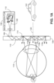
- FIG. 1A is a schematic cross-sectional side view of a waveguide display device in operation.
- An image is projected by an image generator 102.
- the image generator 102 may use one or more of various techniques for projecting an image.
- the image generator 102 may be a laser beam scanning (LBS) projector, a liquid crystal display (LCD), a light-emitting diode (LED) display (including an organic LED (OLED) or micro LED ( ⁇ LED) display), a digital light processor (DLP), a liquid crystal on silicon (LCoS) display, or other type of image generator or light engine.
- LBS laser beam scanning
- LCD liquid crystal display
- LED light-emitting diode
- ⁇ LED micro LED
- DLP digital light processor
- LCDoS liquid crystal on silicon
- Light representing an image 112 generated by the image generator 102 is coupled into a waveguide 104 by a diffractive in-coupler 106.
- the in-coupler 106 diffracts the light representing the image 112 into one or more diffractive orders.
- light ray108 which is one of the light rays representing a portion of the bottom of the image, is diffracted by the in-coupler 106, and one of the diffracted orders 110 (e.g. the second order) is at an angle that is capable of being propagated through the waveguide 104 by total internal reflection.
- At least a portion of the light 110 that has been coupled into the waveguide 104 by the diffractive in-coupler 106 is coupled out of the waveguide by a diffractive out-coupler 114.
- At least some of the light coupled out of the waveguide 104 replicates the incident angle of light coupled into the waveguide.
- out-coupled light rays 116a, 116b, and 116c replicate the angle of the in-coupled light ray 108. Because light exiting the out-coupler replicates the directions of light that entered the in-coupler, the waveguide substantially replicates the original image 112. A user's eye 118 can focus on the replicated image.
- the out-coupler 114 out-couples only a portion of the light with each reflection allowing a single input beam (such as beam 108) to generate multiple parallel output beams (such as beams 116a, 116b, and 116c). In this way, at least some of the light originating from each portion of the image is likely to reach the user's eye even if the eye is not perfectly aligned with the center of the out-coupler. For example, if the eye 118 were to move downward, beam 116c may enter the eye even if beams 116a and 116b do not, so the user can still perceive the bottom of the image 112 despite the shift in position.
- the out-coupler 114 thus operates in part as an exit pupil expander in the vertical direction.
- the waveguide may also include one or more additional exit pupil expanders (not shown in FIG. 1A ) to expand the exit pupil in the horizontal direction.
- the waveguide 104 is at least partly transparent with respect to light originating outside the waveguide display.
- the light 120 from real-world objects such as object 122 traverses the waveguide 104, allowing the user to see the real-world objects while using the waveguide display.
- the diffraction grating 114 As light 120 from real-world objects also goes through the diffraction grating 114, there will be multiple diffraction orders and hence multiple images.
- the diffraction order zero no deviation by 114 to have a great diffraction efficiency for light 120 and order zero, while higher diffraction orders are lower in energy.
- the out-coupler 114 is preferably configured to let through the zero order of the real image. In such embodiments, images displayed by the waveguide display may appear to be superimposed on the real world.
- a waveguide display includes more than one waveguide layer.
- Each waveguide layer may be configured to preferentially convey light with a particular range of wavelengths and/or incident angles from the image generator to the viewer.
- waveguide displays having in-couplers, out-couplers, and pupil expanders may have various different configurations.
- An example layout of one binocular waveguide display is illustrated in FIG. 1B .
- the display includes waveguides 152a, 152b for the left and right eyes, respectively.
- the waveguides include in-couplers 154a,b, pupil expanders 156a,b, and components 158a,b, which operate as both out-couplers and horizontal pupil expanders.
- the pupil expanders 156a,b are arranged along an optical path between the in-coupler and the out-coupler.
- An image generator (not shown) may be provided for each eye and arranged to project light representing an image on the respective in-coupler.
- different features of the waveguide displays may be provided on different surfaces of the waveguides.
- the in-coupler and the out-coupler may both be arranged on the anterior surface of the waveguide (away from the user's eye).
- the in-coupler and/or the out-coupler may be on a posterior surface of the waveguide (toward the user's eye).
- the in-coupler and out-coupler may be on opposite surfaces of the waveguide.
- one or more of an out-coupler, and a pupil expander may be present on both surfaces of the waveguide.
- the image generator may be arranged toward the anterior surface or toward the posterior surface of the waveguide.
- the in-coupler is not necessarily on the same side of the waveguide as the image generator. Any pupil expanders in a waveguide may be arranged on the anterior surface, on the posterior surface, or on both surfaces of the waveguide. In displays with more than one waveguide layer, different layers may have different configurations of in-coupler, out-coupler, and pupil expander.
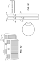
- FIG. 1D is a schematic exploded view of a double waveguide display according to some embodiments, including an image generator 170, a first waveguide (WG 1 ) 172, and a second waveguide (WG 2 ) 174.
- FIG. 1E is a schematic side-view of a double waveguide display according to some embodiments, including an image generator 176, a first waveguide (WG 1 ) 178, and a second waveguide (WG 2 ) 180.
- the first waveguide includes a first transmissive diffractive in-coupler (DG1) 180 and a first diffractive out-coupler (DG6) 182.
- the second waveguide has a second transmissive diffractive in-coupler (DG2) 184, a reflective diffractive in-coupler (DG3) 186, a second diffractive out-coupler (DG4) 188, and a third diffractive out-coupler (DG5) 190.
- DG2 transmissive diffractive in-coupler
- DG3 reflective diffractive in-coupler
- DG4 second diffractive out-coupler
- DG5 third diffractive out-coupler
- Different embodiments may use different arrangements of optical components (such as different arrangements of pupil expanders) on the first and second waveguides.
- FIGs. 1A-1E illustrate the use of waveguides in a near-eye display
- the same principles may be used in other display technologies, such as head up displays for automotive or other uses.
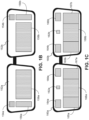
- FIGs. 2A-2B illustrate an example arrangement of optical features on a waveguide according to some embodiments.
- a substantially planar waveguide 200 has a first surface (e.g. a front surface) 202 and a second surface (e.g. a rear surface) 204 that is on the opposite surface of the waveguide 200 from the first surface.
- the first surface 202 includes an in-coupler 206 and an out-coupler 208. While the out-coupler 208 may also operate as a horizontal pupil expander, it is referred to herein as an out-coupler to avoid confusion with other features that operate as pupil expanders.
- pupil expanders 210 and 212 lie along an optical path from the in-coupler 206 to the out-coupler 208.
- pupil expanders 214 and 216 lie along the optical path from the in-coupler 206 to the out-coupler 208.
- the second surface 204 is illustrated in FIG. 2B in the same orientation as the first surface (i.e., illustrated as if the first surface were invisible).
- pupil expanders 218 and 220 lie along the optical path from the in-coupler 206 to the out-coupler 208.
- pupil expanders 222 and 224 lie along an optical path from the in-coupler 206 to the out-coupler 208.
- pupil expander 210 is substantially opposite pupil expander 218, pupil expander 212 is substantially opposite pupil expander 220, pupil expander 214 is substantially opposite pupil expander 222, and pupil expander 216 is substantially opposite pupil expander 224.
- the pupil expanders are illustrated as being rectangular, but different shapes and configurations of pupil expanders are contemplated in different embodiments.
- the shapes and configurations of the in-coupler 206 and the out-coupler 208 are not limited to those illustrated in FIGs. 2A-2B .
- in-coupler 206 and out-coupler 208 are both illustrated on the first surface 202. In other embodiments, one or both of in-coupler 206 and out-coupler 208 are on the second surface 204.
- FIGs. 3A-3B are schematic illustrations showing an example orientation of the diffraction grating lines of each of the pupil expanders 210, 212, 214, 216, 218, 220, 222, 224.
- the grating lines of each pupil expander are oriented such that a normal to the grating lines makes an angle ⁇ K with respect to incident light (as projected onto the plane of the waveguide).
- ⁇ K ⁇ 45° for each of the pupil expanders.
- ⁇ K may have values other than ⁇ 45°, and it may have different values for different ones of the pupil expanders.
- the pupil expanders on the first surface of the waveguide are configured to preferentially diffract light with a first polarization, e.g. p-polarization, also referred to as transverse-magnetic (TM) polarization, at an angle that propagates through the waveguide.
- the pupil expanders on the second surface of the waveguide are configured to preferentially diffract light with a second polarization, e.g. s-polarization, also referred to as transverse-electric (TE) polarization, at an angle that propagates through the waveguide.
- a second polarization e.g. s-polarization
- TE transverse-electric
- the pupil expanders instead of using s-polarization versus p-polarization, are configured to use left-circular polarization versus right-circular polarization. Other complementary sets of polarization directions may alternatively be used.
- the pupil expanders on the first surface of the waveguide are configured to preferentially diffract light representing a first portion of an image coupled into the in-coupler, such as an upper portion of the image, at an angle that propagates through the waveguide.
- the pupil expanders on the second surface of the waveguide are configured to preferentially diffract light representing a second portion of an image coupled into the in-coupler, such as a lower portion of the image, at an angle that propagates through the waveguide.
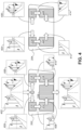
- FIG. 4 An example of the operation of a waveguide display according to some embodiments is illustrated schematically in FIG. 4 .
- a complete image 402 is coupled into an in-coupler 206 of the waveguide.
- Light from the left half 404 of the image is diffracted into a range of angles that propagates leftward through the waveguide.
- Light from the right half 406 of the image is diffracted into a range of angles that propagates rightward through the waveguide.
- the pupil expanders on the first surface 202 of the waveguide are configured to diffract light representing the top half of the image 402 into a range of angles that propagate through the waveguide.
- the left half 404 of the image reaches pupil expander 210.
- Pupil expander 210 is configured to diffract the top portion 408 of the left half toward pupil expander 212.
- Pupil expander 212 is configured to diffract the top-left portion 408 of the image toward the out-coupler 208.
- the right half 406 of the image reaches pupil expander 214.
- Pupil expander 214 is configured to diffract the top portion 410 of the right half toward pupil expander 216.
- Pupil expander 216 is configured to diffract the top-right portion 410 of the image toward the out-coupler 208.
- the pupil expanders on the second surface 204 of the waveguide are configured to diffract light representing the bottom half of the image 402 into a range of angles that propagate through the waveguide.
- the left half 404 of the image reaches pupil expander 218.
- Pupil expander 218 is configured to diffract the bottom portion 412 of the left half toward pupil expander 220.
- Pupil expander 220 is configured to diffract the bottom-left portion 412 of the image toward the out-coupler 208.
- the right half 406 of the image reaches pupil expander 222.
- Pupil expander 222 is configured to diffract the bottom portion 414 of the right half toward pupil expander 224.
- Pupil expander 224 is configured to diffract the bottom-right portion 414 of the image toward the out-coupler 208.
- the pupil expanders 210 and 212 on the first surface of the left side are configured to preferentially diffract light with a first propagation direction corresponding to a first polarization state but to reflect light (via total internal reflection, or via high-efficiency zero-order diffraction) with a second, substantially complementary polarization state.
- the pupil expanders 218 and 220 on the second surface of the left side are configured to preferentially diffract light with the second polarization state but to reflect light (via total internal reflection, or via high-efficiency zero-order diffraction) with the first polarization state.
- the pupil expanders 210 and 212 may be configured to preferentially diffract p-polarized light and to reflect s-polarized light, while the pupil expanders 218 and 220 may be configured to preferentially diffract s-polarized light and to reflect p-polarized light (or vice versa).
- light that is diffracted to a zero-order mode within the waveguide is referred to as being reflected.
- the pupil expanders 214 and 216 on the first surface of the right side are configured to preferentially diffract light with a first polarization state but to reflect light (via total internal reflection, or via high-efficiency zero-order diffraction) with a second, substantially complementary polarization state.
- the pupil expanders 222 and 224 on the second surface of the right side are configured to preferentially diffract light with the second polarization state but to reflect light with the first polarization state.
- the pupil expanders 214 and 216 may be configured to preferentially diffract p-polarized light and to reflect s-polarized light, while the pupil expanders 222 and 224 may be configured to preferentially diffract s-polarized light and to reflect p-polarized light (or vice versa).
- a potential benefit of using polarization-selective diffraction gratings is as follows.
- pupil expander 212 is less likely to direct light from pupil expander 218 toward the out-coupler. Otherwise, light diffracted first by pupil expander 218 (on the second surface) and subsequently by pupil expander 212 (on the first surface) could be coupled out of the waveguide in the wrong direction, appearing as stray light that diminishes the quality of the displayed image.
- each quarter of the display has rays emitted with polar and azimuth angles into a specific trigonometric sector (see for example FIG. 6B ).
- the corresponding EPE may have a pitch size that is configured to handle those directions. If another direction impinges on the first EPE, the ray may not satisfy the TIR condition and may escape from the waveguide.
- each pupil expander is paired with another pupil expander on the same side (e.g. pupil expanders 210 and 212 on the first surface). It may be noted that in other embodiments, each pupil expander may be paired with a pupil expander on the other side.
- pupil expanders 210 on the first surface and 220 on the second surface use the same polarization and are configured to direct the same portion of the in-coupled image toward the out-coupler, and similar changes can be made to the other pupil expanders.
- the in-coupled image 402 is schematically illustrated as being neatly divided into quadrants 408, 410, 412, 414. It should be understood that in practical embodiments, the different portions of the image may overlap to some degree and may have different sizes and irregular shapes.
- FIG. 4 illustrates image flow inside of an optical system according to some embodiments.
- the display's area is divided into four parts.
- the in-coupler is splitting half of the width of the display into one direction inside of the waveguide and the other half into the opposite direction.
- both eye pupil expander (EPE) regions have a top grating on one side of the glass wafer and a bottom EPE on the opposite side of the glass wafer.
- the top EPE has a pitch size that preferentially TIR-diffracts only the top of display's content while the bottom EPE has a pitch size that TIR-diffracts the bottom image content.
- the vertical field of view of an AR headset based on diffractive optics is limited by gratings used as EPEs.
- the design of the EPE calls for selection of the grating's pitch in order to optimize it for the desired vertical field of view.
- the geometry is generally set for deviating a symmetrically distributed beam. This involves an assumption that the display is centered on the optical axis of the projection lens and that the angular distribution of azimuth orientations is symmetrical. This in turn means that the top part of the display (positive azimuth angles) will produce only azimuth angles of a specific sign while the bottom part of the display (below the optical axis) will produce azimuth angles of the opposite sign.
- the azimuth angle average is ⁇ , hence here, instead of measuring angles over [0,2 ⁇ ], the azimuth angles may be measured over [- ⁇ ,+ ⁇ ].
- the grating's pitch size in another way.
- Example embodiments use EPE regions with two different gratings in TIR conical mounting, one for the top of the display and one for the bottom of the display, that act as beam deviators and expanders.
- these gratings involve the use of two gratings in a single EPE region, these gratings are set at different locations. In some embodiments, one is set on one face of the waveguide and the other one on the opposite face. We can call them top and bottom EPE. Hence, the image flow inside of the waveguide is divided as shown in FIG. 4 .
- FIG. 5 is a schematic perspective view of the waveguide of FIG. 4 .
- One issue addressed by some embodiments is to enable the light emitted by the top part of the display to be diffracted only by one of the gratings in the EPE region, either the top or bottom one, and to enable the light emitted by the bottom part of the display to be diffracted by the remaining grating.
- the top and bottom EPE gratings act on different polarizations.
- the top EPE may primarily diffract s-polarized light, while if it is hit by p-polarized light, the p-polarized light reflects back by TIR inside of the waveguide.
- the bottom EPE has the opposite property, preferentially diffracting p-polarized light and reflecting s-polarized light by TIR.
- the light engine or other image generator emits light of both polarizations.
- the in-coupler is able to diffract both polarizations, s and p.
- the in-coupler operates to diffract one half of the display's image into one diffraction mode inside of the waveguide, while it diffracts the other half into the complementary mode into the opposite direction.
- the image generator may use light of different (e.g. complementary) polarizations for different portions of the images.
- the image generator may use s-polarization for an upper portion of the image and p-polarization for a lower portion of the image, or vice-versa.
- the image generator may use left-circular polarization for an upper portion of the image and right-circular polarization for a lower portion of the image, or vice-versa.
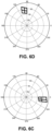
- FIG. 6A illustrates the top-right part of the display area.
- FIG. 6B illustrates the angular polar and azimuth space the display is emitting.
- FIG. 6C illustrates the angular space occupied by rays diffracted after the in-coupler.
- FIG. 6D illustrates angular space occupied by rays diffracted after the top EPE.
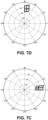
- FIG. 7A illustrates the bottom-right part of the display area.
- FIG. 7B illustrates angular polar and azimuth space the display is emitting.
- FIG. 7C illustrates angular space occupied by rays diffracted after the in-coupler.
- FIG. 7D illustrates angular space occupied by rays diffracted after the bottom EPE.
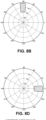
- FIGs. 8A-8D illustrate an expected display size and field of view possible for the right half of a system with a conventional EPE.
- FIG. 8B illustrates the angular bandpass after the EPE.
- FIG. 8C illustrates the angular bandpass before the in-coupler.
- FIG. 8D illustrates the angular bandpass after the in-coupler.
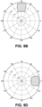
- FIGs. 9A-9D illustrate an example display size and field of view possible in a system with top and bottom gratings for an EPE.
- incident light at an angle ⁇ i g 4 ° diffracts to the grazing angle
- FIG. 9B illustrates the angular bandpass after the EPE.
- FIG. 9C illustrates the angular bandpass before the in-coupler.
- FIG. 9D illustrates the angular bandpass after the in-coupler.
- FIGs. 8A-8D Comparing FIGs. 8A-8D with 9A-9D, it is possible to see the effect on the vertical field of view in embodiments that split the EPE for the top and bottom display areas. Particularly comparing FIG. 8C with FIG. 9C , it is seen that the vertical field of view has substantially doubled with the use of cross-polarized EPE gratings.
- an x-polarized ray 1006 incident on eye pupil expander 1002 is primarily diffracted to order M (1008). Another portion may be diffracted to order zero (1010).
- the x-polarized ray is primarily reflected by total internal reflection (1012).
- a y-polarized ray 1014 incident on eye pupil expander 1002 is primarily reflected by total internal reflection (1016).
- the y-polarized ray is primarily diffracted to order M (1018).
- Another portion may be diffracted to order zero (1020).
- a y-polarized ray 1022 incident on eye pupil expander 1004 is primarily diffracted to order M (1024). Another portion may be diffracted to order zero (1026).
- the y-polarized ray is primarily reflected by total internal reflection (1028).
- an x-polarized ray 1030 incident on eye pupil expander 1004 is primarily reflected by total internal reflection (1032).
- the x-polarized ray is primarily diffracted to order M (1034).
- Another portion may be diffracted to order zero (1036).
- the eye pupil expanders 1002 and 1004 of FIGs. 10A-10D may correspond to any of the opposing pairs of eye pupil expanders described herein, such as eye pupil expander pairs 210 and 218, 212 and 220, 214 and 222, or 216 and 224.
- An apparatus includes: a waveguide having an in-coupler and an out-coupler; a first diffraction grating along an optical path from the in-coupler to the out-coupler wherein the first diffraction grating is configured to preferentially diffract light having a first polarization state; a second diffraction grating along the optical path from the in-coupler to the out-coupler, wherein the second diffraction grating is configured to preferentially diffract light having a second polarization state substantially complementary to the first polarization state.
- Either or both of the first and second diffraction gratings may be a pupil expander.
- a diffraction grating is configured to preferentially diffract light having a first polarization state when the diffraction grating has a greater diffraction efficiency for light having the first polarization state than for light having a second polarization state that is complementary (e.g. perpendicular, in the case of linear polarization) to the first polarization state.
- the first polarization state is p-polarization and the second polarization state is s-polarization.
- the in-coupler is configured to couple at least a first portion of a field of view and a second portion of the field of view into the waveguide, the first diffraction grating is configured to direct the first portion of the field of view along the optical path to the out-coupler, and the second diffraction grating is configured to direct the second portion of the field of view along the optical path to the out-coupler.
- a third diffraction grating is provided along the optical path from the in-coupler to the out-coupler, where the third diffraction grating is configured to preferentially diffract light having the first polarization state, and a fourth diffraction grating along the optical path from the in-coupler to the out-coupler, where the fourth diffraction grating is configured to preferentially diffract light having the second polarization state.
- the in-coupler is configured to couple at least a first portion of a field of view and a second portion of the field of view into the waveguide; the first diffraction grating and the third diffraction grating are configured to cooperatively direct the first portion of the field of view along the optical path to the out-coupler; and the second diffraction grating and the fourth diffraction grating are configured to cooperatively direct the second portion of the field of view along the optical path to the out-coupler.
- the first and second diffraction gratings are arranged in at least partially overlapping positions on opposite surfaces of the waveguide. In some embodiments, the third and fourth diffraction gratings are arranged in at least partially overlapping positions on opposite surfaces of the waveguide.
- An apparatus includes: an image generator configured to generate an image having an upper portion and a lower portion; a waveguide having an in-coupler and an out-coupler, the in-coupler being arranged to couple the upper and lower portions of the image along an optical path to the out-coupler; and along the optical path, at least a first and a second polarization-selective diffraction grating configured to cooperatively direct the upper portion of the image toward the out-coupler and at least a third and a fourth polarization-selective diffraction grating configured to cooperatively direct the lower portion of the image toward the out-coupler.
- One or more of the diffraction gratings may be a pupil expander.
- the first and second polarization-selective diffraction gratings are configured to preferentially diffract light having a first polarization
- the third and a fourth polarization-selective diffraction gratings are configured to preferentially diffract light having a second polarization substantially complementary to the first polarization
- the first polarization state is p-polarization and the second polarization state is s-polarization. In other embodiments, the first polarization state is s-polarization and the second polarization state is p-polarization.
- the first and second diffraction gratings have a first grating period and the third and fourth diffraction gratings have a second grating period different from the first grating period.
- the image generator is operative to generate an image with unpolarized light.
- the first and second diffraction grating are on a first surface of the waveguide and the third and fourth diffraction grating are on a second surface of the waveguide opposite the first surface.
- the upper and lower portions of the image are partly overlapping.
- An apparatus includes: an image generator configured to generate an image having a left portion and a right portion, the left portion including an upper-left quadrant and a lower-left quadrant, the right portion including an upper-right quadrant and a lower-right quadrant; a waveguide having an in-coupler and an out-coupler, the in-coupler being arranged to couple the left portion of the image along a first optical path to the out-coupler and to couple the right portion of the image along a second optical path to the out-coupler; along the first optical path, at least a first and a second polarization-selective diffraction grating configured to cooperatively direct the upper-left quadrant toward the out-coupler and at least a third and a fourth polarization-selective diffraction grating configured to cooperatively direct the lower-left quadrant toward the out-coupler; and along the second optical path, at least a fifth and a sixth polarization-selective diffraction grating configured
- the first and second polarization-selective diffraction gratings are configured to preferentially diffract light having a first polarization
- the third and a fourth polarization-selective diffraction gratings are configured to preferentially diffract light having a second polarization substantially complementary to the first polarization
- the fifth and sixth polarization-selective diffraction gratings are configured to preferentially diffract light having the first polarization
- the seventh and eighth polarization-selective diffraction gratings are configured to preferentially diffract light having the second polarization.
- the first polarization state is p-polarization and the second polarization state is s-polarization. In other embodiments, the first polarization state is s-polarization and the second polarization state is p-polarization.
- the first, second, fifth, and sixth diffraction gratings have a first grating period and the third, fourth, seventh, and eighth diffraction gratings have a second grating period different from the first grating period.
- the image generator is operative to generate an image with unpolarized light.
- the first, second, fifth, and sixth diffraction gratings are on a first surface of the waveguide and the third, fourth, seventh, and eighth diffraction gratings are on a second surface of the waveguide opposite the first surface.
- the method includes: generating an image having an upper portion and a lower portion; coupling the upper and lower portions of the image into a waveguide using an in-coupler of the waveguide; directing the upper portion of the image along an optical path from the in-coupler of the waveguide to an out-coupler of the waveguide using at least a first and a second polarization-selective diffraction grating; and directing the lower portion of the image along the optical path using at least a third and a fourth polarization-selective diffraction grating.
- the first and second polarization-selective diffraction gratings are configured to preferentially diffract light having a first polarization
- the third and a fourth polarization-selective diffraction gratings are configured to preferentially diffract light having a second polarization substantially complementary to the first polarization
- the first polarization state is p-polarization and the second polarization state is s-polarization. In other embodiments, the first polarization state is s-polarization and the second polarization state is p-polarization.
- the first and second diffraction gratings have a first grating period and the second and third diffraction gratings have a second grating period different from the first grating period.
- generating an image comprises generating an image with unpolarized light.
Landscapes
- Physics & Mathematics (AREA)
- General Physics & Mathematics (AREA)
- Optics & Photonics (AREA)
- Diffracting Gratings Or Hologram Optical Elements (AREA)
Claims (15)
- Vorrichtung zum Anzeigen eines Bilds, wobei die Vorrichtung umfasst:einen Wellenleiter (200) mit einem Einkoppler (206) und mit einem Auskoppler (208);dadurch gekennzeichnet, dass die Vorrichtung ferner umfasst:ein erstes Beugungsgitter (210) und ein zweites Beugungsgitter (212) entlang eines ersten optischen Wegs von dem Einkoppler zu dem Auskoppler, wobei das erste und das zweite Beugungsgitter für Licht mit einem ersten Polarisationszustand eine höhere Beugungseffizienz als für Licht mit einem zweiten Polarisationszustand, der zu dem ersten Polarisationszustand komplementär ist, aufweisen; undein drittes Beugungsgitter (218) und ein viertes Beugungsgitter (220) entlang des ersten optischen Wegs, wobei das dritte und das vierte Beugungsgitter für Licht mit dem zweiten Polarisationszustand eine höhere Beugungseffizienz als für Licht mit dem ersten Polarisationszustand, aufweisen;wobei der Einkoppler an einer Oberfläche des Wellenleiters (200) angeordnet ist und zum Beugen von Licht mit dem ersten Polarisationszustand und von Licht mit dem zweiten Polarisationszustand konfiguriert ist.
- Vorrichtung nach Anspruch 1, die ferner umfasst:einen Bildgenerator (170, 176), der zum Erzeugen eines Bilds mit einem oberen Teil und mit einem unteren Teil konfiguriert ist, wobei der Einkoppler zum Koppeln des oberen und des unteren Teils des Bilds in den Wellenleiter angeordnet ist;wobei das erste und das zweite Beugungsgitter dafür konfiguriert sind, den oberen Teil des Bilds zusammenwirkend zu dem Auskoppler zu leiten, und das dritte und das vierte Beugungsgitter dafür konfiguriert sind, den unteren Teil des Bilds zusammenwirkend zu dem Auskoppler zu leiten.
- Vorrichtung nach Anspruch 1, die ferner umfasst:einen Bildgenerator (170, 176), der zum Erzeugen eines Bilds mit einem linken Teil und mit einem rechten Teil konfiguriert ist, wobei der linke Teil einen linken oberen Quadranten und einen linken unteren Quadranten enthält, wobei der rechte Teil einen rechten oberen Quadranten und einen rechten unteren Quadranten enthält;wobei der Einkoppler dafür angeordnet ist, den linken Teil des Bilds entlang des ersten optischen Wegs zu dem Auskoppler zu koppeln und den rechten Teil des Bilds entlang eines zweiten optischen Wegs zu dem Auskoppler zu koppeln;wobei das erste und das zweite Beugungsgitter dafür konfiguriert sind, den linken oberen Quadranten zusammenwirkend zu dem Auskoppler zu leiten, und das dritte und des vierte Beugungsgitter dafür konfiguriert sind, den linken unteren Quadranten zusammenwirkend zu dem Auskoppler zu leiten;wobei die Vorrichtung ferner umfasst:ein fünftes Beugungsgitter (214) und ein sechstes Beugungsgitter (216) entlang des zweiten optischen Wegs, wobei das fünfte und das sechste Beugungsgitter für Licht mit dem ersten Polarisationszustand eine höhere Beugungseffizienz als für Licht mit dem zweiten Polarisationszustand aufweisen, wobei das fünfte und das sechste Beugungsgitter dafür konfiguriert sind, den rechten oberen Quadranten zusammenwirkend zu dem Auskoppler zu leiten; undein siebentes Beugungsgitter (222) und ein achtes Beugungsgitter (224) entlang des zweiten optischen Wegs, wobei das siebente und das achte Beugungsgitter für Licht mit einem zweiten Polarisationszustand eine höhere Beugungseffizienz als für Licht mit dem ersten Polarisationszustand aufweisen, wobei der siebente und das achte Beugungsgitter dafür konfiguriert sind, zusammenwirkend den rechten unteren Quadranten zu dem Auskoppler zu leiten.
- Vorrichtung nach einem der vorhergehenden Ansprüche, wobei der erste Polarisationszustand der p-Polarisationszustand oder der s-Polarisationszustand ist und der zweite Polarisationszustand der andere des p-Polarisationszustands und des s-Polarisationszustands ist.
- Vorrichtung nach einem der vorhergehenden Ansprüche, wobei das erste und das dritte Beugungsgitter an mindestens teilweise überlappenden Positionen auf gegenüberliegenden Oberflächen des Wellenleiters angeordnet sind.
- Vorrichtung nach einem der vorhergehenden Ansprüche, wobei das zweite und das vierte Beugungsgitter an mindestens teilweise überlappenden Positionen auf gegenüberliegenden Oberflächen des Wellenleiters angeordnet sind.
- Vorrichtung nach einem der vorhergehenden Ansprüche, wobei das erste und das zweite Beugungsgitter eine erste Gitterperiode aufweisen und das dritte und das vierte Beugungsgitter eine zweite Gitterperiode, die von der ersten Gitterperiode verschieden ist, aufweisen.
- Vorrichtung nach Anspruch 2 oder 3, wobei der Bildgenerator dafür betreibbar ist, ein Bild mit unpolarisiertem Licht zu erzeugen.
- Verfahren, das umfasst:Erzeugen eines Bilds;Koppeln des Bilds in einen Wellenleiter unter Verwendung eines Einkopplers des Wellenleiters;Leiten eines ersten Teils des Bilds entlang eines ersten optischen Wegs von dem Einkoppler des Wellenleiters zu einem Auskoppler des Wellenleiters unter Verwendung mindestens eines ersten und eines zweiten Beugungsgitters, wobei das erste und das zweite Beugungsgitter für Licht mit einem ersten Polarisationszustand eine höhere Beugungseffizienz als für Licht mit einem zweiten Polarisationszustand, der zu dem ersten Polarisationszustand komplementär ist, aufweisen; undLeiten eines zweiten Teils des Bilds entlang des ersten optischen Wegs von dem Einkoppler des Wellenleiters zu dem Auskoppler des Wellenleiters unter Verwendung mindestens eines dritten und eines vierten Beugungsgitters, wobei das dritte und das vierte Beugungsgitter für Licht mit einem zweiten Polarisationszustand eine höhere Beugungseffizienz als für Licht mit dem ersten Polarisationszustand aufweisen;wobei der Einkoppler an einer Oberfläche des Wellenleiters angeordnet ist und dafür konfiguriert ist, Licht mit dem ersten Polarisationszustand und Licht mit dem zweiten Polarisationszustand zu beugen.
- Verfahren nach Anspruch 9, wobei der erste Teil des Bilds ein oberer Teil des Bilds ist und der zweite Teil des Bilds ein unterer Teil des Bilds ist.
- Verfahren nach Anspruch 9, das ferner umfasst:Leiten eines dritten Teils des Bilds entlang eines zweiten optischen Wegs von dem Einkoppler des Wellenleiters zu dem Auskoppler des Wellenleiters unter Verwendung mindestens eines fünften und eines sechsten Beugungsgitters, wobei das fünfte und das sechste Beugungsgitter für Licht mit dem ersten Polarisationszustand eine höhere Beugungseffizienz als für Licht mit dem zweiten Polarisationszustand aufweisen; undLeiten eines vierten Teils des Bilds entlang des zweiten optischen Wegs von dem Einkoppler des Wellenleiters zu dem Auskoppler des Wellenleiters unter Verwendung mindestens eines siebenten und eines achten Beugungsgitters,wobei das siebente und das achte Beugungsgitter für Licht mit dem zweiten Polarisationszustand eine höhere Beugungseffizienz als für Licht mit dem ersten Polarisationszustand aufweisen.
- Verfahren nach einem der Ansprüche 9 bis 11, wobei der erste Polarisationszustand der p-Polarisationszustand oder der s-Polarisationszustand ist und der zweite Polarisationszustand der andere des p-Polarisationszustands und des s-Polarisationszustands ist.
- Verfahren nach einem der Ansprüche 9 bis 12, wobei das erste und das dritte Beugungsgitter an mindestens teilweise überlappenden Positionen auf gegenüberliegenden Oberflächen des Wellenleiters angeordnet sind.
- Verfahren nach einem der Ansprüche 9 bis 13, wobei das erste und das zweite Beugungsgitter eine erste Gitterperiode aufweisen und das dritte und das vierte Beugungsgitter eine zweite Gitterperiode, die von der ersten Gitterperiode verschieden ist, aufweisen.
- Verfahren nach einem der Ansprüche 9 bis 14, wobei das Bild mit unpolarisiertem Licht erzeugt wird.
Applications Claiming Priority (2)
| Application Number | Priority Date | Filing Date | Title |
|---|---|---|---|
| EP20315121 | 2020-04-06 | ||
| PCT/EP2021/058583 WO2021204656A1 (en) | 2020-04-06 | 2021-04-01 | Waveguide display with cross-polarized eye pupil expanders |
Publications (2)
| Publication Number | Publication Date |
|---|---|
| EP4133325A1 EP4133325A1 (de) | 2023-02-15 |
| EP4133325B1 true EP4133325B1 (de) | 2025-06-04 |
Family
ID=70861387
Family Applications (1)
| Application Number | Title | Priority Date | Filing Date |
|---|---|---|---|
| EP21716190.0A Active EP4133325B1 (de) | 2020-04-06 | 2021-04-01 | Wellenleiteranzeige mit kreuzpolarisierten augenpupillenexpandierern |
Country Status (4)
| Country | Link |
|---|---|
| US (1) | US12306405B2 (de) |
| EP (1) | EP4133325B1 (de) |
| CN (1) | CN115485605A (de) |
| WO (1) | WO2021204656A1 (de) |
Families Citing this family (6)
| Publication number | Priority date | Publication date | Assignee | Title |
|---|---|---|---|---|
| CN116324587A (zh) * | 2020-08-13 | 2023-06-23 | 交互数字Ce专利控股有限公司 | 通过c形平面光学架构的低失真成像 |
| US20240264354A1 (en) * | 2021-06-10 | 2024-08-08 | Interdigital Ce Patent Holdings, Sas | Dual diffraction grating in-coupler for reduced waveguide thickness background |
| CN113933997A (zh) * | 2021-10-21 | 2022-01-14 | 上海交通大学 | 基于双通道波导的近眼显示装置 |
| CN118355313A (zh) * | 2021-12-16 | 2024-07-16 | 谷歌有限责任公司 | 具有多个光学路径的光学波导 |
| US12282163B2 (en) * | 2021-12-30 | 2025-04-22 | Goertek Inc. | Optical waveguide system and electronic device |
| WO2023215339A1 (en) * | 2022-05-06 | 2023-11-09 | Google Llc | Waveguide input coupler multiplexing to reduce exit pupil expansion ray footprint |
Family Cites Families (9)
| Publication number | Priority date | Publication date | Assignee | Title |
|---|---|---|---|---|
| US10234686B2 (en) * | 2015-11-16 | 2019-03-19 | Microsoft Technology Licensing, Llc | Rainbow removal in near-eye display using polarization-sensitive grating |
| CN108780224B (zh) * | 2016-03-24 | 2021-08-03 | 迪吉伦斯公司 | 用于提供偏振选择性全息波导装置的方法和设备 |
| US9791703B1 (en) | 2016-04-13 | 2017-10-17 | Microsoft Technology Licensing, Llc | Waveguides with extended field of view |
| US10061124B2 (en) * | 2016-04-29 | 2018-08-28 | Microsoft Technology Licensing, Llc | Robust architecture for large field of view components |
| US10551622B2 (en) | 2016-10-26 | 2020-02-04 | Microsoft Technology Licensing, Llc | Field of view tiling in waveguide-based near-eye displays |
| FI130178B (en) | 2018-03-28 | 2023-03-29 | Dispelix Oy | Waveguide element and waveguide stack for display use |
| WO2019237051A1 (en) * | 2018-06-08 | 2019-12-12 | Magic Leap, Inc. | Method and system for projection display with polarization selective reflectors |
| EP3671293A1 (de) | 2018-12-21 | 2020-06-24 | Thomson Licensing | Optische vorrichtung mit mindestens einem beugungsgitter mit einem gitterpegel über der wellenlänge |
| CN110471185A (zh) * | 2019-08-28 | 2019-11-19 | 瑞声通讯科技(常州)有限公司 | 波导增强现实显示装置 |
-
2021
- 2021-04-01 WO PCT/EP2021/058583 patent/WO2021204656A1/en not_active Ceased
- 2021-04-01 EP EP21716190.0A patent/EP4133325B1/de active Active
- 2021-04-01 US US17/916,498 patent/US12306405B2/en active Active
- 2021-04-01 CN CN202180032575.XA patent/CN115485605A/zh active Pending
Also Published As
| Publication number | Publication date |
|---|---|
| US12306405B2 (en) | 2025-05-20 |
| EP4133325A1 (de) | 2023-02-15 |
| US20230176382A1 (en) | 2023-06-08 |
| CN115485605A (zh) | 2022-12-16 |
| WO2021204656A1 (en) | 2021-10-14 |
Similar Documents
| Publication | Publication Date | Title |
|---|---|---|
| EP4133325B1 (de) | Wellenleiteranzeige mit kreuzpolarisierten augenpupillenexpandierern | |
| US11668935B2 (en) | Waveguide image combiners for augmented reality displays | |
| EP4031927B1 (de) | Optische vorrichtung zum koppeln eines hohen blickfeldes von einfallendem licht | |
| JP6867999B2 (ja) | 反射型転換アレイを有する結像光ガイド | |
| JP6720315B2 (ja) | 反射型転換アレイを有する結像光ガイド | |
| EP4016166B1 (de) | Vorrichtung der erweiterten realität zur bereitstellung von dreidimensionaler erweiterter realität und betriebsverfahren dafür | |
| US11994684B2 (en) | Image light guide with zoned diffractive optic | |
| US12326562B2 (en) | Waveguide display system with wide field of view | |
| US11209652B2 (en) | Light guide with polarization separator for dual images | |
| US20240361592A1 (en) | Full color eye-pupil-expanders with high vertical field of view | |
| US20230400618A1 (en) | Single mode full color waveguide combiner using asymmetric transmissive and reflective diffraction gratings | |
| US12449583B2 (en) | Low distortion imaging through a C-shape flat optical architecture | |
| CN115398284A (zh) | 非偏振光光栅入耦合器 | |
| US20240385364A1 (en) | Double-sided waveguide | |
| WO2022258725A1 (en) | Dual diffraction grating in-coupler for reduced waveguide thickness | |
| WO2022008378A1 (en) | Reflective in-coupler design with high refractive index element using second diffraction order for near-eye displays | |
| JP7818103B2 (ja) | デュアルインデックス導波路スタック | |
| WO2024006638A1 (en) | Multiplexing image light guide with split input and optical power | |
| CN118974612A (zh) | 多波长范围成像光导系统 | |
| US20230273449A1 (en) | Full-color waveguide combiner with embedded metagrating | |
| WO2022157228A1 (en) | Uniform incoupler for conical incidence | |
| EP4359846A1 (de) | Leckagenunterdrückung für austrittspupillenexpander |
Legal Events
| Date | Code | Title | Description |
|---|---|---|---|
| STAA | Information on the status of an ep patent application or granted ep patent |
Free format text: STATUS: UNKNOWN |
|
| STAA | Information on the status of an ep patent application or granted ep patent |
Free format text: STATUS: THE INTERNATIONAL PUBLICATION HAS BEEN MADE |
|
| PUAI | Public reference made under article 153(3) epc to a published international application that has entered the european phase |
Free format text: ORIGINAL CODE: 0009012 |
|
| STAA | Information on the status of an ep patent application or granted ep patent |
Free format text: STATUS: REQUEST FOR EXAMINATION WAS MADE |
|
| 17P | Request for examination filed |
Effective date: 20221012 |
|
| AK | Designated contracting states |
Kind code of ref document: A1 Designated state(s): AL AT BE BG CH CY CZ DE DK EE ES FI FR GB GR HR HU IE IS IT LI LT LU LV MC MK MT NL NO PL PT RO RS SE SI SK SM TR |
|
| DAV | Request for validation of the european patent (deleted) | ||
| DAX | Request for extension of the european patent (deleted) | ||
| GRAP | Despatch of communication of intention to grant a patent |
Free format text: ORIGINAL CODE: EPIDOSNIGR1 |
|
| STAA | Information on the status of an ep patent application or granted ep patent |
Free format text: STATUS: GRANT OF PATENT IS INTENDED |
|
| RIC1 | Information provided on ipc code assigned before grant |
Ipc: G02B 27/10 20060101ALN20241217BHEP Ipc: G02B 27/28 20060101ALI20241217BHEP Ipc: G02B 27/01 20060101AFI20241217BHEP |
|
| INTG | Intention to grant announced |
Effective date: 20250108 |
|
| GRAJ | Information related to disapproval of communication of intention to grant by the applicant or resumption of examination proceedings by the epo deleted |
Free format text: ORIGINAL CODE: EPIDOSDIGR1 |
|
| STAA | Information on the status of an ep patent application or granted ep patent |
Free format text: STATUS: REQUEST FOR EXAMINATION WAS MADE |
|
| GRAP | Despatch of communication of intention to grant a patent |
Free format text: ORIGINAL CODE: EPIDOSNIGR1 |
|
| STAA | Information on the status of an ep patent application or granted ep patent |
Free format text: STATUS: GRANT OF PATENT IS INTENDED |
|
| GRAS | Grant fee paid |
Free format text: ORIGINAL CODE: EPIDOSNIGR3 |
|
| P01 | Opt-out of the competence of the unified patent court (upc) registered |
Free format text: CASE NUMBER: APP_11395/2025 Effective date: 20250307 |
|
| INTC | Intention to grant announced (deleted) | ||
| RIC1 | Information provided on ipc code assigned before grant |
Ipc: G02B 27/10 20060101ALN20250320BHEP Ipc: G02B 27/28 20060101ALI20250320BHEP Ipc: G02B 27/01 20060101AFI20250320BHEP |
|
| INTG | Intention to grant announced |
Effective date: 20250328 |
|
| GRAA | (expected) grant |
Free format text: ORIGINAL CODE: 0009210 |
|
| STAA | Information on the status of an ep patent application or granted ep patent |
Free format text: STATUS: THE PATENT HAS BEEN GRANTED |
|
| AK | Designated contracting states |
Kind code of ref document: B1 Designated state(s): AL AT BE BG CH CY CZ DE DK EE ES FI FR GB GR HR HU IE IS IT LI LT LU LV MC MK MT NL NO PL PT RO RS SE SI SK SM TR |
|
| REG | Reference to a national code |
Ref country code: GB Ref legal event code: FG4D |
|
| REG | Reference to a national code |
Ref country code: CH Ref legal event code: EP |
|
| REG | Reference to a national code |
Ref country code: DE Ref legal event code: R096 Ref document number: 602021031751 Country of ref document: DE |
|
| REG | Reference to a national code |
Ref country code: IE Ref legal event code: FG4D |
|
| REG | Reference to a national code |
Ref country code: NL Ref legal event code: MP Effective date: 20250604 |
|
| PG25 | Lapsed in a contracting state [announced via postgrant information from national office to epo] |
Ref country code: ES Free format text: LAPSE BECAUSE OF FAILURE TO SUBMIT A TRANSLATION OF THE DESCRIPTION OR TO PAY THE FEE WITHIN THE PRESCRIBED TIME-LIMIT Effective date: 20250604 Ref country code: FI Free format text: LAPSE BECAUSE OF FAILURE TO SUBMIT A TRANSLATION OF THE DESCRIPTION OR TO PAY THE FEE WITHIN THE PRESCRIBED TIME-LIMIT Effective date: 20250604 |
|
| REG | Reference to a national code |
Ref country code: LT Ref legal event code: MG9D |
|
| PG25 | Lapsed in a contracting state [announced via postgrant information from national office to epo] |
Ref country code: NO Free format text: LAPSE BECAUSE OF FAILURE TO SUBMIT A TRANSLATION OF THE DESCRIPTION OR TO PAY THE FEE WITHIN THE PRESCRIBED TIME-LIMIT Effective date: 20250904 Ref country code: GR Free format text: LAPSE BECAUSE OF FAILURE TO SUBMIT A TRANSLATION OF THE DESCRIPTION OR TO PAY THE FEE WITHIN THE PRESCRIBED TIME-LIMIT Effective date: 20250905 |
|
| PG25 | Lapsed in a contracting state [announced via postgrant information from national office to epo] |
Ref country code: PL Free format text: LAPSE BECAUSE OF FAILURE TO SUBMIT A TRANSLATION OF THE DESCRIPTION OR TO PAY THE FEE WITHIN THE PRESCRIBED TIME-LIMIT Effective date: 20250604 |
|
| PG25 | Lapsed in a contracting state [announced via postgrant information from national office to epo] |
Ref country code: BG Free format text: LAPSE BECAUSE OF FAILURE TO SUBMIT A TRANSLATION OF THE DESCRIPTION OR TO PAY THE FEE WITHIN THE PRESCRIBED TIME-LIMIT Effective date: 20250604 |
|
| PG25 | Lapsed in a contracting state [announced via postgrant information from national office to epo] |
Ref country code: HR Free format text: LAPSE BECAUSE OF FAILURE TO SUBMIT A TRANSLATION OF THE DESCRIPTION OR TO PAY THE FEE WITHIN THE PRESCRIBED TIME-LIMIT Effective date: 20250604 |
|
| PG25 | Lapsed in a contracting state [announced via postgrant information from national office to epo] |
Ref country code: RS Free format text: LAPSE BECAUSE OF FAILURE TO SUBMIT A TRANSLATION OF THE DESCRIPTION OR TO PAY THE FEE WITHIN THE PRESCRIBED TIME-LIMIT Effective date: 20250904 |
|
| PG25 | Lapsed in a contracting state [announced via postgrant information from national office to epo] |
Ref country code: LV Free format text: LAPSE BECAUSE OF FAILURE TO SUBMIT A TRANSLATION OF THE DESCRIPTION OR TO PAY THE FEE WITHIN THE PRESCRIBED TIME-LIMIT Effective date: 20250604 |
|
| PG25 | Lapsed in a contracting state [announced via postgrant information from national office to epo] |
Ref country code: NL Free format text: LAPSE BECAUSE OF FAILURE TO SUBMIT A TRANSLATION OF THE DESCRIPTION OR TO PAY THE FEE WITHIN THE PRESCRIBED TIME-LIMIT Effective date: 20250604 |
|
| PG25 | Lapsed in a contracting state [announced via postgrant information from national office to epo] |
Ref country code: PT Free format text: LAPSE BECAUSE OF FAILURE TO SUBMIT A TRANSLATION OF THE DESCRIPTION OR TO PAY THE FEE WITHIN THE PRESCRIBED TIME-LIMIT Effective date: 20251006 |
|
| REG | Reference to a national code |
Ref country code: AT Ref legal event code: MK05 Ref document number: 1800873 Country of ref document: AT Kind code of ref document: T Effective date: 20250604 |
|
| PG25 | Lapsed in a contracting state [announced via postgrant information from national office to epo] |
Ref country code: IS Free format text: LAPSE BECAUSE OF FAILURE TO SUBMIT A TRANSLATION OF THE DESCRIPTION OR TO PAY THE FEE WITHIN THE PRESCRIBED TIME-LIMIT Effective date: 20251004 |
|
| PG25 | Lapsed in a contracting state [announced via postgrant information from national office to epo] |
Ref country code: AT Free format text: LAPSE BECAUSE OF FAILURE TO SUBMIT A TRANSLATION OF THE DESCRIPTION OR TO PAY THE FEE WITHIN THE PRESCRIBED TIME-LIMIT Effective date: 20250604 Ref country code: SM Free format text: LAPSE BECAUSE OF FAILURE TO SUBMIT A TRANSLATION OF THE DESCRIPTION OR TO PAY THE FEE WITHIN THE PRESCRIBED TIME-LIMIT Effective date: 20250604 |
|
| PG25 | Lapsed in a contracting state [announced via postgrant information from national office to epo] |
Ref country code: CZ Free format text: LAPSE BECAUSE OF FAILURE TO SUBMIT A TRANSLATION OF THE DESCRIPTION OR TO PAY THE FEE WITHIN THE PRESCRIBED TIME-LIMIT Effective date: 20250604 |
|
| PG25 | Lapsed in a contracting state [announced via postgrant information from national office to epo] |
Ref country code: EE Free format text: LAPSE BECAUSE OF FAILURE TO SUBMIT A TRANSLATION OF THE DESCRIPTION OR TO PAY THE FEE WITHIN THE PRESCRIBED TIME-LIMIT Effective date: 20250604 |
|
| PG25 | Lapsed in a contracting state [announced via postgrant information from national office to epo] |
Ref country code: SK Free format text: LAPSE BECAUSE OF FAILURE TO SUBMIT A TRANSLATION OF THE DESCRIPTION OR TO PAY THE FEE WITHIN THE PRESCRIBED TIME-LIMIT Effective date: 20250604 |
|
| PG25 | Lapsed in a contracting state [announced via postgrant information from national office to epo] |
Ref country code: IT Free format text: LAPSE BECAUSE OF FAILURE TO SUBMIT A TRANSLATION OF THE DESCRIPTION OR TO PAY THE FEE WITHIN THE PRESCRIBED TIME-LIMIT Effective date: 20250604 |
|
| REG | Reference to a national code |
Ref country code: DE Ref legal event code: R097 Ref document number: 602021031751 Country of ref document: DE |
|
| PLBE | No opposition filed within time limit |
Free format text: ORIGINAL CODE: 0009261 |
|
| STAA | Information on the status of an ep patent application or granted ep patent |
Free format text: STATUS: NO OPPOSITION FILED WITHIN TIME LIMIT |
|
| PG25 | Lapsed in a contracting state [announced via postgrant information from national office to epo] |
Ref country code: DK Free format text: LAPSE BECAUSE OF FAILURE TO SUBMIT A TRANSLATION OF THE DESCRIPTION OR TO PAY THE FEE WITHIN THE PRESCRIBED TIME-LIMIT Effective date: 20250604 |
|
| REG | Reference to a national code |
Ref country code: CH Ref legal event code: L10 Free format text: ST27 STATUS EVENT CODE: U-0-0-L10-L00 (AS PROVIDED BY THE NATIONAL OFFICE) Effective date: 20260416 |