EP4132675B1 - Selbstreinigender filter - Google Patents
Selbstreinigender filter Download PDFInfo
- Publication number
- EP4132675B1 EP4132675B1 EP21719968.6A EP21719968A EP4132675B1 EP 4132675 B1 EP4132675 B1 EP 4132675B1 EP 21719968 A EP21719968 A EP 21719968A EP 4132675 B1 EP4132675 B1 EP 4132675B1
- Authority
- EP
- European Patent Office
- Prior art keywords
- cleaning
- self
- internal surface
- filter
- opening
- Prior art date
- Legal status (The legal status is an assumption and is not a legal conclusion. Google has not performed a legal analysis and makes no representation as to the accuracy of the status listed.)
- Active
Links
Images


Classifications
-
- B—PERFORMING OPERATIONS; TRANSPORTING
- B01—PHYSICAL OR CHEMICAL PROCESSES OR APPARATUS IN GENERAL
- B01D—SEPARATION
- B01D29/00—Filters with filtering elements stationary during filtration, e.g. pressure or suction filters, not covered by groups B01D24/00 - B01D27/00; Filtering elements therefor
- B01D29/11—Filters with filtering elements stationary during filtration, e.g. pressure or suction filters, not covered by groups B01D24/00 - B01D27/00; Filtering elements therefor with bag, cage, hose, tube, sleeve or like filtering elements
- B01D29/31—Self-supporting filtering elements
- B01D29/35—Self-supporting filtering elements arranged for outward flow filtration
-
- B—PERFORMING OPERATIONS; TRANSPORTING
- B01—PHYSICAL OR CHEMICAL PROCESSES OR APPARATUS IN GENERAL
- B01D—SEPARATION
- B01D29/00—Filters with filtering elements stationary during filtration, e.g. pressure or suction filters, not covered by groups B01D24/00 - B01D27/00; Filtering elements therefor
- B01D29/62—Regenerating the filter material in the filter
- B01D29/64—Regenerating the filter material in the filter by scrapers, brushes, nozzles, or the like, acting on the cake side of the filtering element
- B01D29/6407—Regenerating the filter material in the filter by scrapers, brushes, nozzles, or the like, acting on the cake side of the filtering element brushes
- B01D29/6415—Regenerating the filter material in the filter by scrapers, brushes, nozzles, or the like, acting on the cake side of the filtering element brushes with a rotary movement with respect to the filtering element
-
- B—PERFORMING OPERATIONS; TRANSPORTING
- B01—PHYSICAL OR CHEMICAL PROCESSES OR APPARATUS IN GENERAL
- B01D—SEPARATION
- B01D29/00—Filters with filtering elements stationary during filtration, e.g. pressure or suction filters, not covered by groups B01D24/00 - B01D27/00; Filtering elements therefor
- B01D29/62—Regenerating the filter material in the filter
- B01D29/66—Regenerating the filter material in the filter by flushing, e.g. counter-current air-bumps
- B01D29/68—Regenerating the filter material in the filter by flushing, e.g. counter-current air-bumps with backwash arms, shoes or nozzles
- B01D29/682—Regenerating the filter material in the filter by flushing, e.g. counter-current air-bumps with backwash arms, shoes or nozzles with a rotary movement with respect to the filtering element
-
- B—PERFORMING OPERATIONS; TRANSPORTING
- B01—PHYSICAL OR CHEMICAL PROCESSES OR APPARATUS IN GENERAL
- B01D—SEPARATION
- B01D29/00—Filters with filtering elements stationary during filtration, e.g. pressure or suction filters, not covered by groups B01D24/00 - B01D27/00; Filtering elements therefor
- B01D29/62—Regenerating the filter material in the filter
- B01D29/66—Regenerating the filter material in the filter by flushing, e.g. counter-current air-bumps
- B01D29/68—Regenerating the filter material in the filter by flushing, e.g. counter-current air-bumps with backwash arms, shoes or nozzles
- B01D29/688—Regenerating the filter material in the filter by flushing, e.g. counter-current air-bumps with backwash arms, shoes or nozzles with backwash arms or shoes acting on the cake side
-
- B—PERFORMING OPERATIONS; TRANSPORTING
- B01—PHYSICAL OR CHEMICAL PROCESSES OR APPARATUS IN GENERAL
- B01D—SEPARATION
- B01D35/00—Filtering devices having features not specifically covered by groups B01D24/00 - B01D33/00, or for applications not specifically covered by groups B01D24/00 - B01D33/00; Auxiliary devices for filtration; Filter housing constructions
- B01D35/14—Safety devices specially adapted for filtration; Devices for indicating clogging
- B01D35/147—Bypass or safety valves
-
- B—PERFORMING OPERATIONS; TRANSPORTING
- B01—PHYSICAL OR CHEMICAL PROCESSES OR APPARATUS IN GENERAL
- B01D—SEPARATION
- B01D2201/00—Details relating to filtering apparatus
- B01D2201/08—Regeneration of the filter
- B01D2201/081—Regeneration of the filter using nozzles or suction devices
- B01D2201/082—Suction devices placed on the cake side of the filtering element
Definitions
- the present invention relates to a self-cleaning filter for liquids.
- a filter is particularly usable whenever it is necessary to remove solid particulates and/or insoluble liquid from a liquid to be filtered, usually water.
- Such a system is usually used in purification plants, treatment plants, or for the filtration of water for industrial, civil, naval or other use.
- Such filters comprise an inlet opening, a delivery opening, a tubular element for filtering the liquid flowing from the inlet opening to the delivery opening, and a plurality of shoes arranged inside the tubular element, in particular in proximity to the internal surface.
- Such shoes rotating with respect to a central axis, are capable of sweeping substantially the entire internal surface of the tubular element.
- the shoes are each provided with a respective suction opening, capable of withdrawing dirt from the internal surface of the tubular element.
- the suction shoes are T-shaped and have a longitudinally extending suction slot.
- Such suction shoes were unsatisfactory in terms of flow/suction flow distribution along the suction slot. In fact, it is maximum in the central part at the discharge opening of the shoe and minimum in the end parts.
- a further filter is shown in EP 3424578 A1 , in the name of the same Applicant.
- Such a filter is similar to the previous ones, but comprises brushes fixed to the suction shoes. The combined action of the brushes and suction allows to significantly improve the efficiency of the self-cleaning system with respect to the previous filters.
- the filter described in EP 3044165 A1 is further known.
- the suction openings of the shoes are selectively activatable.
- the shoes act without suction, but only through the mechanical action of the brushes. This mode removes coarser dirt, which is then made to outflow through a first discharge line, connected in fluid communication with the internal surface of the tubular element.
- the suction openings of the shoes are activated, so as to collect the finer dirt particles. Such dirt particles are then expelled through a second discharge line, placed in fluid communication with the suction openings.
- All the known self-cleaning filters except for the filter of EP ⁇ 578, require a prefilter connected upstream of the self-cleaning filter itself.
- a prefilter has the function of removing the larger particles of contaminant dirt which would otherwise quickly saturate the self-cleaning filter.
- Such prefilters comprise a grille which intercepts the liquid flow upstream of the self-cleaning filter.
- the prefilters must be subject to a maintenance cycle distinct from that of the self-cleaning filter.
- the prefilters are periodically extracted and cleaned by the operator by hand. To carry out this operation it is necessary to block the system, losing the main advantage of the self-cleaning of the filter.
- the filter of EP ⁇ 578 manages to overcome the disadvantage of the prefilter by carrying out a two-stage cleaning process, which is capable of removing both the largest and the smallest dirt particles from the inside of the filter. It should be noted, however, that this advantageous solution is achieved by significantly increasing the complexity of the filter, since it requires the presence of two separate discharge lines, one for coarse dirt and the other for finer dirt.
- the technical task underlying the present invention is to propose a self-cleaning filter which overcomes the drawbacks of the prior art mentioned above.
- an object of the present invention is to provide a self-cleaning filter which does not require a prefilter and, at the same time, which simplifies the hydraulic connections to the system and the control of the cleaning process.
- a self-cleaning filter according to the present invention comprises the technical features of claim 1.
- Such a device solves the technical problem, as it can operate in two distinct steps.
- the rubbing carried out by the contact cleaning means i.e., by the brushes, allows the larger dirt particles to be detached from the filter by mechanical action.
- the suction acts mainly through the latter and not through the suction apertures of the cleaning elements, allowing the coarsest dirt to be removed and made to outflow to the discharge line directly through the bypass valve.
- This filter operating mode no longer requires the prefilter as in the state of the art, since the larger particles settle directly inside the self-cleaning filter and can be disposed of during a normal cleaning cycle.
- the cleaning cycle of the self-cleaning filter according to the present invention allows both coarse and fine dirt to flow through a single discharge line, thereby simplifying both the structure of the filter and the control of the cleaning process. In fact, to switch from one mode to another it is necessary to act exclusively on the bypass valve, while the suction is kept active throughout the cycle.
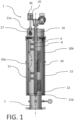
- the number 1 indicates a self-cleaning filter in accordance with an embodiment of the present invention.
- the filter 1 comprises a casing 21.
- This casing 21 encloses a volume adapted to contain both the fluid to be filtered and the filtered fluid.
- the casing 21 has a first 21a and a second end 21b arranged along a longitudinal development direction "A".
- the longitudinal development direction "A" can be oriented horizontally, vertically or in any other intermediate direction.
- the casing 21 has an inlet opening 2 through which the fluid to be filtered is introduced.
- the casing 21 also has a delivery opening 3 from which the filtered fluid flows.
- the casing 21 is further provided with a discharge opening 24, distinct from the delivery opening 3, the function of which will be illustrated in a subsequent part of the present description.
- a tubular filtering element 10 is inserted in the casing 21.
- a tubular element 10 is configured to be passed through by a fluid to be filtered.
- the tubular element 10 extends in particular along the aforementioned longitudinal development axis "A".
- the tubular element 10 is arranged between the ends 21a, 21b of the casing 21 and, even more preferably, has a cylindrical shape.
- the tubular element 10 consists of a filtering mesh.
- the tubular element 10 defines an internal zone 22 within the casing 21.
- Such an internal zone 22 is adapted to be placed in communication with a source of fluid to be filtered, in particular through the inlet opening 2.
- An internal surface 10a faces the internal zone 22, and is adapted to receive and retain the suspended contaminant in the fluid to be filtered.
- An external surface 10b is opposite the internal surface 10a.
- the tubular element 10 further defines an external zone 23 within the casing 21.
- Such an external zone 23 is in particular comprised between the external surface 10b of the tubular element 10 and the casing 21.
- the external zone 23 receives the filtered fluid from the tubular element 10 and allows it to flow through the delivery opening 3.
- the self-cleaning filter 1 comprises one or more cleaning elements 4 placed within the internal zone 23.
- the cleaning elements 4 are spaced from each other along the longitudinal development direction "A". Multiple elements can be placed in the same position on the longitudinal axis "A". In this case, these cleaning elements 4 are arranged angularly equally spaced from each other around the longitudinal development axis "A". Preferably, the cleaning elements 4 arranged adjacent along the longitudinal development direction "A" are angularly spaced by 120°.
- the cleaning elements 4 are in particular configured to rotate around the longitudinal development direction "A".
- the filter 1 comprises a hollow shaft 8 arranged centrally and oriented along the longitudinal development direction "A".
- the cleaning element 4 are connected to the shaft 8 which, by rotating, rotates them with respect to the tubular element 10.
- each cleaning element 4 has an advancement direction "B".
- each cleaning element travels along the internal surface 10a advancing along an advancement direction "B", as shown for example in figure 4 .
- each cleaning element 4 comprises a suction aperture 5.
- the suction aperture 5 faces the internal surface 10a of the tubular element 10, in particular placed near the internal surface 10a, in particular in contact therewith.
- Such a first suction aperture 5 has the function of sucking the filtered impurities from the internal surface 10a of the tubular element 10.
- the suction aperture 5 comprises a slot 15, preferably of constant width, which extends along the longitudinal development direction "A" for more than 90% of the length of the cleaning element 4.
- the cleaning elements 4 are spaced along the longitudinal development direction "A" so that, following the rotation thereof around the longitudinal development direction "A" of the tubular element 10, the surfaces swept by the suction apertures 5 of two adjacent cleaning elements 4 overlap with a ratio of overlapping area to total area of the suction aperture 5 in a range between 5% and 35%.
- Each cleaning element 4 comprises in particular a pair of rods 6 and a shoe 7.
- Each rod 6 is oriented radially with respect to the tubular element 10.
- each rod 6 has a first end 6a and a second end 6b. The first end 6a is connected to the shaft 8 mentioned above.
- the shoe 7 is connected to the second ends 6b of the rods 6, and is in particular arranged transversely with respect thereto. Said shoe 6 is arranged in a zone near the internal surface 10a of the tubular element 10, in particular substantially in contact therewith.
- each cleaning element 4 is provided with quick connection means 19 active between the rod 6 and the shoe 7.
- Such quick connection means 19 have the function of connecting/disconnecting the rod 6 from the shoe 7.
- the quick connection means 19 ensure a stable fixing of the shoe 7 on the rod 6, useful in particular when the cleaning element 4 is extracted from the tubular element 10 to perform maintenance operations.
- shoe 7 extends substantially parallel to the longitudinal development direction "A".
- the first suction aperture 5, described above, is obtained on the shoe 7.
- Each cleaning element 4 can advantageously comprise at least one elastic element 37, in particular an elastic bellows, connected to the shoe 7 and configured to push it against the internal surface 10a.
- the shoe 7 can be made of plastic material.
- each cleaning element 4 comprises contact cleaning means 9, arranged in particular on the shoe 7.
- Such contact cleaning means 9 are configured to rub on the internal surface 10a of the tubular element 10, so as to remove dirt.
- the contact cleaning means 9 are positioned in front of the first suction aperture 5 along the advancement direction "B".
- the contact cleaning means 9 comprise a plurality of brushes 11.
- Each brush 11 is fixed to a respective cleaning element 4, and is configured to slide in contact with the internal surface 10a of the tubular element 10 along the aforementioned advancement direction "B".
- the brush 11 allows a greater amount of dirt to be removed by mechanic al action.
- each cleaning element 4 has a seat 12, in particular obtained on the shoe 7.
- the aforementioned brush 11 is arranged inside the seat 12.
- each brush 11 is insertable/removable in/from the seat 12, so as to be connected/disconnected to the respective cleaning element 4.
- a pair of plugs fixes the brush 11 inside the seat 12. Such plugs are in themselves a fixing mechanism known to those skilled in the art, and will therefore not be described further.
- the removability of the brushes 11 allows to replace them when they are worn and/or to select a particular type of brush 11 more suitable for the particular type of tubular element 10 mounted in the filter 1.
- the self-cleaning filter 1 further comprises a suction conduit 16 arranged within the tubular element 10, in particular within the shaft 8, and configured to rotate with respect to the tubular element 10.
- the suction conduit 16 is arranged coaxially with respect to the tubular element 10.
- the cleaning elements 4 are fixed in rotation to the suction conduit 16 and project radially from the suction conduit 16.
- connection conduit 16 has a plurality of connection openings 17.
- Each connection opening 17 is connected to a respective cleaning element 4 through a respective connection conduit 18.
- connection conduit is defined within at least one of the two rods 6 forming the cleaning element 4, preferably within both rods 6.
- the above-mentioned discharge opening 24 is arranged to expel the dirt removed from the internal surface 10a.
- the discharge opening 24 is placed in fluid communication with the internal zone 22 and, in particular, with the suction apertures 5 of the cleaning elements 4.
- the filter 1 further comprises a discharge valve 25 placed at the discharge opening 24.
- the discharge opening 24 is formed at the first end 21a of the casing 21.
- a chamber 27 is arranged coaxially to the tubular element 10, and is placed at the first end 21a.
- the discharge opening 24 is formed at such a chamber 27.
- the aforementioned shaft 8 coaxially passes through the chamber 27.
- the filter 1 is provided with at least one bypass valve 30.
- a bypass valve 30 is placed in parallel with respect to the suction apertures 5 of the cleaning elements 4.
- the bypass valve 30 can be opened, so as to put the internal zone 22 directly in fluid communication with the discharge opening 24.
- the bypass valve 30 is placed between the internal zone 22 and the chamber 27.
- the filter 1 comprises a single bypass valve 30. In alternative embodiments, not shown, there can be any number of bypass valves 30.
- the bypass valve 30 comprises a bypass opening 31, which is placed between the chamber 27 and the internal zone 22.
- the filter 1 comprises a separation wall 34 arranged between the chamber 27 and the internal zone 22. The bypass opening 31 is then formed on the wall 34.
- a stem 32 is associated with the bypass opening 31, and is movable with respect thereto to open and/or close it.
- the stem is oriented substantially parallel to the longitudinal development direction "A".
- the bypass valve 30 further comprises actuating means 33 for the stem 32, so as to be able to move it with respect to the bypass opening 30.
- actuating means 33 comprise a cylinder 35 and a piston 36, inserted in the cylinder 35 and slidable therein.
- the piston 36 is connected to the stem 32, in particular to the opposite end of the bypass opening 31.
- the cylinder 35 and the piston 36 are of a pneumatic type.
- the piston 35 and the cylinder 36 can be of another type, for example of the hydraulic type.
- the actuating means 33 can be of any type, as long as they are suitable for the purpose.
- the actuating means 33 can comprise an electric linear actuator.
- the object of the present invention is also a self-cleaning process of the filter 1 described above.
- a rough cleaning is carried out by rotating the cleaning elements 4 to sweep the internal surface 10a of the tubular element 10.
- fluid is sucked from the discharge opening 24, and the bypass valve 30 is opened.
- the contaminant mainly the larger particles, is removed from the brushes 11 and flows predominantly from the bypass opening 31 directly to the discharge opening 24.
- the cleaning elements 4 move exclusively along a circumferential direction of the internal surface 10a of the tubular element 10.
- the shoes 7 do not move along a direction parallel to the longitudinal development direction "A" of the filter 1.
Landscapes
- Chemical & Material Sciences (AREA)
- Chemical Kinetics & Catalysis (AREA)
- Filtering Of Dispersed Particles In Gases (AREA)
- Separation Of Suspended Particles By Flocculating Agents (AREA)
- Detergent Compositions (AREA)
Claims (11)
- Selbstreinigender Filter (1), umfassend:- ein Gehäuse (21), das eine Einlassöffnung (2) zum Abziehen von zu filterndem Fluid aufweist, eine Abgabeöffnung (3) zum Strömenlassen eines gefilterten Fluids, und eine Abflussöffnung (24), die von der Abgabeöffnung (3) getrennt ist;- ein rohrförmiges Filterelement (10), das in das Gehäuse (21) eingesetzt und konfiguriert ist, um von einem zu filternden Fluid durchflossen zu werden, wobei das rohrförmige Element (10) eine innere Zone (22) innerhalb des Gehäuses (21) in Fluidverbindung mit der Einlassöffnung (2) und eine äußere Zone (23) definiert, die in Fluidverbindung mit der Abgabeöffnung (3) eingerichtet ist, wobei das rohrförmige Element (10) ferner eine innere Oberfläche (10a), die der inneren Zone (22) zugewandt ist, und eine Längsausdehnungsrichtung (A) aufweist;- ein oder mehrere Reinigungselemente (4), die innerhalb der inneren Zone (22) platziert und konfiguriert sind, um sich in Bezug auf die Längsausdehnungsrichtung (A) zu drehen, wobei jedes Reinigungselement (4) eine Saugöffnung (5) umfasst, die der inneren Oberfläche (10a) zugewandt ist und in der Nähe und bevorzugt in Kontakt mit der inneren Oberfläche (10a) platziert ist, um Verunreinigung von der inneren Oberfläche (10a) zu saugen, Kontaktreinigungsmittel (9), die konfiguriert sind, um an der inneren Oberfläche (10a) zu reiben, um Verunreinigung von der inneren Oberfläche (10a) zu entfernen, wobei die Abflussöffnung (24) in Fluidverbindung mit den Saugöffnungen (5) platziert ist;dadurch gekennzeichnet, dass es ein Bypassventil (30) umfasst, das parallel in Bezug auf die Saugöffnungen (5) platziert ist und geöffnet werden kann, um die interne Zone (22) in direkte Fluidverbindung mit der Abflussöffnung (24) zu bringen.
- Selbstreinigender Filter (1) nach dem vorstehenden Anspruch, dadurch gekennzeichnet, dass er eine Kammer (27) umfasst, die koaxial zu dem rohrförmigen Element (10) eingerichtet und an einem Ende (21a, 21b) des Gehäuses (21) platziert ist, wobei die Abflussöffnung (24) an der Kammer (27) erhalten wird, wobei das Bypassventil (30) zwischen der inneren Zone (22) und der Kammer (27) platziert ist.
- Selbstreinigender Filter (1) nach dem vorstehenden Anspruch, dadurch gekennzeichnet, dass das Bypassventil (30) eine Bypassöffnung (31), die zwischen der Kammer (27) und der inneren Zone (22) platziert ist, einen Schaft (32), der der Bypassöffnung (31) zugeordnet ist und in Bezug auf die Bypassöffnung (31) bewegbar ist, um sie zu öffnen/schließen, Betätigungsmittel (33) des Schafts (32), um ihn in Bezug auf die Bypassöffnung (31) zu bewegen, umfasst.
- Selbstreinigender Filter (1) nach dem vorstehenden Anspruch, dadurch gekennzeichnet, dass er eine Wand (34) umfasst, die zwischen der Kammer (27) und der inneren Zone (22) eingerichtet ist, wobei die Bypassöffnung (31) an der Wand (34) gebildet ist.
- Selbstreinigender Filter (1) nach dem vorstehenden Anspruch, dadurch gekennzeichnet, dass die Betätigungsmittel (33) einen Zylinder (35) und einen Kolben (36) umfassen, der mit dem Schaft (32) verbunden ist und innerhalb des Zylinders (35) gleitet.
- Selbstreinigender Filter (1) nach einem der vorstehenden Ansprüche, dadurch gekennzeichnet, dass jedes Reinigungselement (4) eine jeweilige Vorschubrichtung (B) aufweist, wobei die Kontaktreinigungsmittel (9) entlang der Vorschubrichtung (B) vor der ersten Saugöffnung (5) platziert sind.
- Selbstreinigender Filter (1) nach dem vorstehenden Anspruch, dadurch gekennzeichnet, dass das Kontaktreinigungsmittel (9) eine Vielzahl von Bürsten (11) umfasst, die jeweils an einem jeweiligen Reinigungselement (4) befestigt und dazu konfiguriert sind, in Kontakt mit der Innenfläche (10a) des rohrförmigen Elements (10) entlang der Vorschubrichtung (B) zu gleiten.
- Selbstreinigender Filter (1) nach einem der vorstehenden Ansprüche, dadurch gekennzeichnet, dass jedes Reinigungselement (4) einen Schuh (7) umfasst, der mindestens ein elastisches Element aufweist, das dazu konfiguriert ist, den Schuh (7) gegen die Innenfläche (10a) zu schieben.
- Selbstreinigender Prozess eines Filters (1) nach einem der Ansprüche, der die folgenden Schritte umfasst:- Durchführen einer Grobreinigung durch Drehen der Reinigungselemente (4), um die Innenfläche (10a) des rohrförmigen Elements (10) zu fegen und große Verunreinigungsteilchen zu entfernen;- Durchführen einer Feinreinigung durch Drehen der Reinigungselemente (4) und gleichzeitiges Ausüben einer Saugwirkung durch die Saugöffnungen (5) mit ausreichender Stärke, um kleine Verunreinigungsteilchen von der Innenfläche (10a) des rohrförmigen Elements (10) zu entfernen;dadurch gekennzeichnet, dass das Bypassventil (30) während des Grobreinigungsschritts offen und während des Feinreinigungsschritts geschlossen ist, um sowohl große Verunreinigungsteilchen als auch kleine Verunreinigungsteilchen durch die Ablauföffnung (24) abzuleiten.
- Selbstreinigungsverfahren nach dem vorstehenden Anspruch, dadurch gekennzeichnet, dass sowohl der Grobreinigungsschritt als auch der Feinreinigungsschritt durchgeführt werden, indem das Fluid aus der Ablauföffnung (24) gesaugt wird.
- Selbstreinigungsverfahren nach Anspruch 10 oder 11, dadurch gekennzeichnet, dass sich die Reinigungselemente (4) ausschließlich entlang einer Umfangsrichtung der Innenfläche (10a) des rohrförmigen Elements (10) bewegen.
Applications Claiming Priority (2)
| Application Number | Priority Date | Filing Date | Title |
|---|---|---|---|
| IT102020000007459A IT202000007459A1 (it) | 2020-04-08 | 2020-04-08 | Filtro autopulente |
| PCT/IB2021/052629 WO2021205286A1 (en) | 2020-04-08 | 2021-03-30 | Self-cleaning filter |
Publications (2)
| Publication Number | Publication Date |
|---|---|
| EP4132675A1 EP4132675A1 (de) | 2023-02-15 |
| EP4132675B1 true EP4132675B1 (de) | 2024-03-27 |
Family
ID=71111672
Family Applications (1)
| Application Number | Title | Priority Date | Filing Date |
|---|---|---|---|
| EP21719968.6A Active EP4132675B1 (de) | 2020-04-08 | 2021-03-30 | Selbstreinigender filter |
Country Status (5)
| Country | Link |
|---|---|
| EP (1) | EP4132675B1 (de) |
| ES (1) | ES2980615T3 (de) |
| IL (1) | IL297213A (de) |
| IT (1) | IT202000007459A1 (de) |
| WO (1) | WO2021205286A1 (de) |
Families Citing this family (3)
| Publication number | Priority date | Publication date | Assignee | Title |
|---|---|---|---|---|
| CN115090019B (zh) * | 2022-07-14 | 2023-05-26 | 江苏赛德力制药机械制造有限公司 | 全自动多功能过滤器 |
| CN116808674B (zh) * | 2023-08-28 | 2023-11-28 | 新乡市中汇过滤技术有限公司 | 一种浆料过滤器 |
| CN117839304A (zh) * | 2024-01-17 | 2024-04-09 | 海宁市水享净水设备有限公司 | 一种二级前置过滤器 |
Family Cites Families (4)
| Publication number | Priority date | Publication date | Assignee | Title |
|---|---|---|---|---|
| ITVR20110118A1 (it) * | 2011-05-27 | 2012-11-28 | Mauro Bonatti | Filtro particolarmente per acque di irrigazione o industriali |
| US20140021125A1 (en) | 2012-07-18 | 2014-01-23 | Dan Lin | Self-cleaning suction filter |
| HK1223085A1 (zh) | 2013-09-12 | 2017-07-21 | 安特尔处理设施建设工贸股份公司 | 带有电机减速器的吸污嘴刷洗式自动清洁过滤器 |
| IT201700076873A1 (it) | 2017-07-07 | 2019-01-07 | Alfa Water S R L | Filtro autopulente |
-
2020
- 2020-04-08 IT IT102020000007459A patent/IT202000007459A1/it unknown
-
2021
- 2021-03-30 ES ES21719968T patent/ES2980615T3/es active Active
- 2021-03-30 EP EP21719968.6A patent/EP4132675B1/de active Active
- 2021-03-30 IL IL297213A patent/IL297213A/en unknown
- 2021-03-30 WO PCT/IB2021/052629 patent/WO2021205286A1/en not_active Ceased
Also Published As
| Publication number | Publication date |
|---|---|
| WO2021205286A1 (en) | 2021-10-14 |
| IL297213A (en) | 2022-12-01 |
| EP4132675A1 (de) | 2023-02-15 |
| ES2980615T3 (es) | 2024-10-02 |
| IT202000007459A1 (it) | 2021-10-08 |
Similar Documents
| Publication | Publication Date | Title |
|---|---|---|
| EP4132675B1 (de) | Selbstreinigender filter | |
| JP3839074B2 (ja) | 逆流洗浄式フィルタ | |
| US4624785A (en) | Easily-cleanable filters | |
| EP2670506B1 (de) | Rückspülfilter mit spülungsvorrichtung | |
| KR101299806B1 (ko) | 유체 필터 | |
| US8216469B2 (en) | Filter device | |
| CN1260011C (zh) | 磁性过滤器 | |
| KR100513356B1 (ko) | 연속-작동 여과 방법 및 장치 | |
| JP2009517204A (ja) | 洗浄装置 | |
| EP0844013A3 (de) | In-situ zu reinigender Filter mit gefiltertem Reinigungsmittel | |
| EP3077074A1 (de) | Filtrationssystem und filteranordnung damit | |
| EP3530336B1 (de) | Selbstreinigender filter | |
| WO2010026476A2 (en) | Method and device for cleaning a filter for fluids | |
| EP3424578B1 (de) | Selbstreinigender filter | |
| CN115245714A (zh) | 一种纺织车间用粉尘过滤装置 | |
| KR20150085487A (ko) | 청소 장치를 구비하여 공정 중단 없이 액체를 여과하기 위한 장치 및 방법 | |
| CN106974589A (zh) | 抽吸清洁设备 | |
| USRE34218E (en) | Easily-cleanable filters | |
| JP6042700B2 (ja) | 濾過装置 | |
| CA2363588C (en) | Self-cleaning filter | |
| KR200404946Y1 (ko) | 공작기계용 절삭유 세정장치 | |
| CN2817950Y (zh) | 全自动自清洗过滤器 | |
| WO2026003836A1 (en) | Filter cleaning hybrid device | |
| SU1590102A1 (ru) | Самоочищающийс фильтр дл жидкости | |
| KR101648738B1 (ko) | 스크린 및 이를 구비한 스크리닝 장치 |
Legal Events
| Date | Code | Title | Description |
|---|---|---|---|
| STAA | Information on the status of an ep patent application or granted ep patent |
Free format text: STATUS: UNKNOWN |
|
| STAA | Information on the status of an ep patent application or granted ep patent |
Free format text: STATUS: THE INTERNATIONAL PUBLICATION HAS BEEN MADE |
|
| PUAI | Public reference made under article 153(3) epc to a published international application that has entered the european phase |
Free format text: ORIGINAL CODE: 0009012 |
|
| STAA | Information on the status of an ep patent application or granted ep patent |
Free format text: STATUS: REQUEST FOR EXAMINATION WAS MADE |
|
| 17P | Request for examination filed |
Effective date: 20221019 |
|
| AK | Designated contracting states |
Kind code of ref document: A1 Designated state(s): AL AT BE BG CH CY CZ DE DK EE ES FI FR GB GR HR HU IE IS IT LI LT LU LV MC MK MT NL NO PL PT RO RS SE SI SK SM TR |
|
| DAV | Request for validation of the european patent (deleted) | ||
| DAX | Request for extension of the european patent (deleted) | ||
| GRAP | Despatch of communication of intention to grant a patent |
Free format text: ORIGINAL CODE: EPIDOSNIGR1 |
|
| STAA | Information on the status of an ep patent application or granted ep patent |
Free format text: STATUS: GRANT OF PATENT IS INTENDED |
|
| INTG | Intention to grant announced |
Effective date: 20231031 |
|
| GRAS | Grant fee paid |
Free format text: ORIGINAL CODE: EPIDOSNIGR3 |
|
| GRAA | (expected) grant |
Free format text: ORIGINAL CODE: 0009210 |
|
| STAA | Information on the status of an ep patent application or granted ep patent |
Free format text: STATUS: THE PATENT HAS BEEN GRANTED |
|
| AK | Designated contracting states |
Kind code of ref document: B1 Designated state(s): AL AT BE BG CH CY CZ DE DK EE ES FI FR GB GR HR HU IE IS IT LI LT LU LV MC MK MT NL NO PL PT RO RS SE SI SK SM TR |
|
| REG | Reference to a national code |
Ref country code: GB Ref legal event code: FG4D |
|
| REG | Reference to a national code |
Ref country code: CH Ref legal event code: EP |
|
| REG | Reference to a national code |
Ref country code: DE Ref legal event code: R096 Ref document number: 602021010983 Country of ref document: DE |
|
| REG | Reference to a national code |
Ref country code: IE Ref legal event code: FG4D |
|
| PG25 | Lapsed in a contracting state [announced via postgrant information from national office to epo] |
Ref country code: LT Free format text: LAPSE BECAUSE OF FAILURE TO SUBMIT A TRANSLATION OF THE DESCRIPTION OR TO PAY THE FEE WITHIN THE PRESCRIBED TIME-LIMIT Effective date: 20240327 |
|
| REG | Reference to a national code |
Ref country code: LT Ref legal event code: MG9D |
|
| PG25 | Lapsed in a contracting state [announced via postgrant information from national office to epo] |
Ref country code: GR Free format text: LAPSE BECAUSE OF FAILURE TO SUBMIT A TRANSLATION OF THE DESCRIPTION OR TO PAY THE FEE WITHIN THE PRESCRIBED TIME-LIMIT Effective date: 20240628 |
|
| PG25 | Lapsed in a contracting state [announced via postgrant information from national office to epo] |
Ref country code: HR Free format text: LAPSE BECAUSE OF FAILURE TO SUBMIT A TRANSLATION OF THE DESCRIPTION OR TO PAY THE FEE WITHIN THE PRESCRIBED TIME-LIMIT Effective date: 20240327 Ref country code: RS Free format text: LAPSE BECAUSE OF FAILURE TO SUBMIT A TRANSLATION OF THE DESCRIPTION OR TO PAY THE FEE WITHIN THE PRESCRIBED TIME-LIMIT Effective date: 20240627 |
|
| PG25 | Lapsed in a contracting state [announced via postgrant information from national office to epo] |
Ref country code: RS Free format text: LAPSE BECAUSE OF FAILURE TO SUBMIT A TRANSLATION OF THE DESCRIPTION OR TO PAY THE FEE WITHIN THE PRESCRIBED TIME-LIMIT Effective date: 20240627 Ref country code: LT Free format text: LAPSE BECAUSE OF FAILURE TO SUBMIT A TRANSLATION OF THE DESCRIPTION OR TO PAY THE FEE WITHIN THE PRESCRIBED TIME-LIMIT Effective date: 20240327 Ref country code: HR Free format text: LAPSE BECAUSE OF FAILURE TO SUBMIT A TRANSLATION OF THE DESCRIPTION OR TO PAY THE FEE WITHIN THE PRESCRIBED TIME-LIMIT Effective date: 20240327 Ref country code: GR Free format text: LAPSE BECAUSE OF FAILURE TO SUBMIT A TRANSLATION OF THE DESCRIPTION OR TO PAY THE FEE WITHIN THE PRESCRIBED TIME-LIMIT Effective date: 20240628 Ref country code: FI Free format text: LAPSE BECAUSE OF FAILURE TO SUBMIT A TRANSLATION OF THE DESCRIPTION OR TO PAY THE FEE WITHIN THE PRESCRIBED TIME-LIMIT Effective date: 20240327 Ref country code: BG Free format text: LAPSE BECAUSE OF FAILURE TO SUBMIT A TRANSLATION OF THE DESCRIPTION OR TO PAY THE FEE WITHIN THE PRESCRIBED TIME-LIMIT Effective date: 20240327 |
|
| REG | Reference to a national code |
Ref country code: NL Ref legal event code: MP Effective date: 20240327 |
|
| PG25 | Lapsed in a contracting state [announced via postgrant information from national office to epo] |
Ref country code: SE Free format text: LAPSE BECAUSE OF FAILURE TO SUBMIT A TRANSLATION OF THE DESCRIPTION OR TO PAY THE FEE WITHIN THE PRESCRIBED TIME-LIMIT Effective date: 20240327 Ref country code: LV Free format text: LAPSE BECAUSE OF FAILURE TO SUBMIT A TRANSLATION OF THE DESCRIPTION OR TO PAY THE FEE WITHIN THE PRESCRIBED TIME-LIMIT Effective date: 20240327 |
|
| PG25 | Lapsed in a contracting state [announced via postgrant information from national office to epo] |
Ref country code: NL Free format text: LAPSE BECAUSE OF FAILURE TO SUBMIT A TRANSLATION OF THE DESCRIPTION OR TO PAY THE FEE WITHIN THE PRESCRIBED TIME-LIMIT Effective date: 20240327 |
|
| REG | Reference to a national code |
Ref country code: AT Ref legal event code: MK05 Ref document number: 1669378 Country of ref document: AT Kind code of ref document: T Effective date: 20240327 |
|
| PG25 | Lapsed in a contracting state [announced via postgrant information from national office to epo] |
Ref country code: NL Free format text: LAPSE BECAUSE OF FAILURE TO SUBMIT A TRANSLATION OF THE DESCRIPTION OR TO PAY THE FEE WITHIN THE PRESCRIBED TIME-LIMIT Effective date: 20240327 |
|
| REG | Reference to a national code |
Ref country code: ES Ref legal event code: FG2A Ref document number: 2980615 Country of ref document: ES Kind code of ref document: T3 Effective date: 20241002 |
|
| PG25 | Lapsed in a contracting state [announced via postgrant information from national office to epo] |
Ref country code: IS Free format text: LAPSE BECAUSE OF FAILURE TO SUBMIT A TRANSLATION OF THE DESCRIPTION OR TO PAY THE FEE WITHIN THE PRESCRIBED TIME-LIMIT Effective date: 20240727 |
|
| PG25 | Lapsed in a contracting state [announced via postgrant information from national office to epo] |
Ref country code: SM Free format text: LAPSE BECAUSE OF FAILURE TO SUBMIT A TRANSLATION OF THE DESCRIPTION OR TO PAY THE FEE WITHIN THE PRESCRIBED TIME-LIMIT Effective date: 20240327 Ref country code: PT Free format text: LAPSE BECAUSE OF FAILURE TO SUBMIT A TRANSLATION OF THE DESCRIPTION OR TO PAY THE FEE WITHIN THE PRESCRIBED TIME-LIMIT Effective date: 20240729 |
|
| PG25 | Lapsed in a contracting state [announced via postgrant information from national office to epo] |
Ref country code: CZ Free format text: LAPSE BECAUSE OF FAILURE TO SUBMIT A TRANSLATION OF THE DESCRIPTION OR TO PAY THE FEE WITHIN THE PRESCRIBED TIME-LIMIT Effective date: 20240327 Ref country code: EE Free format text: LAPSE BECAUSE OF FAILURE TO SUBMIT A TRANSLATION OF THE DESCRIPTION OR TO PAY THE FEE WITHIN THE PRESCRIBED TIME-LIMIT Effective date: 20240327 |
|
| PG25 | Lapsed in a contracting state [announced via postgrant information from national office to epo] |
Ref country code: AT Free format text: LAPSE BECAUSE OF FAILURE TO SUBMIT A TRANSLATION OF THE DESCRIPTION OR TO PAY THE FEE WITHIN THE PRESCRIBED TIME-LIMIT Effective date: 20240327 |
|
| PG25 | Lapsed in a contracting state [announced via postgrant information from national office to epo] |
Ref country code: PL Free format text: LAPSE BECAUSE OF FAILURE TO SUBMIT A TRANSLATION OF THE DESCRIPTION OR TO PAY THE FEE WITHIN THE PRESCRIBED TIME-LIMIT Effective date: 20240327 |
|
| PG25 | Lapsed in a contracting state [announced via postgrant information from national office to epo] |
Ref country code: SK Free format text: LAPSE BECAUSE OF FAILURE TO SUBMIT A TRANSLATION OF THE DESCRIPTION OR TO PAY THE FEE WITHIN THE PRESCRIBED TIME-LIMIT Effective date: 20240327 |
|
| PG25 | Lapsed in a contracting state [announced via postgrant information from national office to epo] |
Ref country code: SM Free format text: LAPSE BECAUSE OF FAILURE TO SUBMIT A TRANSLATION OF THE DESCRIPTION OR TO PAY THE FEE WITHIN THE PRESCRIBED TIME-LIMIT Effective date: 20240327 Ref country code: SK Free format text: LAPSE BECAUSE OF FAILURE TO SUBMIT A TRANSLATION OF THE DESCRIPTION OR TO PAY THE FEE WITHIN THE PRESCRIBED TIME-LIMIT Effective date: 20240327 Ref country code: RO Free format text: LAPSE BECAUSE OF FAILURE TO SUBMIT A TRANSLATION OF THE DESCRIPTION OR TO PAY THE FEE WITHIN THE PRESCRIBED TIME-LIMIT Effective date: 20240327 Ref country code: PT Free format text: LAPSE BECAUSE OF FAILURE TO SUBMIT A TRANSLATION OF THE DESCRIPTION OR TO PAY THE FEE WITHIN THE PRESCRIBED TIME-LIMIT Effective date: 20240729 Ref country code: PL Free format text: LAPSE BECAUSE OF FAILURE TO SUBMIT A TRANSLATION OF THE DESCRIPTION OR TO PAY THE FEE WITHIN THE PRESCRIBED TIME-LIMIT Effective date: 20240327 Ref country code: IS Free format text: LAPSE BECAUSE OF FAILURE TO SUBMIT A TRANSLATION OF THE DESCRIPTION OR TO PAY THE FEE WITHIN THE PRESCRIBED TIME-LIMIT Effective date: 20240727 Ref country code: EE Free format text: LAPSE BECAUSE OF FAILURE TO SUBMIT A TRANSLATION OF THE DESCRIPTION OR TO PAY THE FEE WITHIN THE PRESCRIBED TIME-LIMIT Effective date: 20240327 Ref country code: CZ Free format text: LAPSE BECAUSE OF FAILURE TO SUBMIT A TRANSLATION OF THE DESCRIPTION OR TO PAY THE FEE WITHIN THE PRESCRIBED TIME-LIMIT Effective date: 20240327 Ref country code: AT Free format text: LAPSE BECAUSE OF FAILURE TO SUBMIT A TRANSLATION OF THE DESCRIPTION OR TO PAY THE FEE WITHIN THE PRESCRIBED TIME-LIMIT Effective date: 20240327 |
|
| REG | Reference to a national code |
Ref country code: CH Ref legal event code: PL |
|
| PG25 | Lapsed in a contracting state [announced via postgrant information from national office to epo] |
Ref country code: LU Free format text: LAPSE BECAUSE OF NON-PAYMENT OF DUE FEES Effective date: 20240330 |
|
| PG25 | Lapsed in a contracting state [announced via postgrant information from national office to epo] |
Ref country code: LU Free format text: LAPSE BECAUSE OF NON-PAYMENT OF DUE FEES Effective date: 20240330 |
|
| REG | Reference to a national code |
Ref country code: BE Ref legal event code: MM Effective date: 20240331 |
|
| REG | Reference to a national code |
Ref country code: DE Ref legal event code: R097 Ref document number: 602021010983 Country of ref document: DE |
|
| PG25 | Lapsed in a contracting state [announced via postgrant information from national office to epo] |
Ref country code: MC Free format text: LAPSE BECAUSE OF FAILURE TO SUBMIT A TRANSLATION OF THE DESCRIPTION OR TO PAY THE FEE WITHIN THE PRESCRIBED TIME-LIMIT Effective date: 20240327 |
|
| PG25 | Lapsed in a contracting state [announced via postgrant information from national office to epo] |
Ref country code: DK Free format text: LAPSE BECAUSE OF FAILURE TO SUBMIT A TRANSLATION OF THE DESCRIPTION OR TO PAY THE FEE WITHIN THE PRESCRIBED TIME-LIMIT Effective date: 20240327 |
|
| PG25 | Lapsed in a contracting state [announced via postgrant information from national office to epo] |
Ref country code: BE Free format text: LAPSE BECAUSE OF NON-PAYMENT OF DUE FEES Effective date: 20240331 |
|
| PG25 | Lapsed in a contracting state [announced via postgrant information from national office to epo] |
Ref country code: IE Free format text: LAPSE BECAUSE OF NON-PAYMENT OF DUE FEES Effective date: 20240330 |
|
| PG25 | Lapsed in a contracting state [announced via postgrant information from national office to epo] |
Ref country code: MC Free format text: LAPSE BECAUSE OF FAILURE TO SUBMIT A TRANSLATION OF THE DESCRIPTION OR TO PAY THE FEE WITHIN THE PRESCRIBED TIME-LIMIT Effective date: 20240327 Ref country code: IE Free format text: LAPSE BECAUSE OF NON-PAYMENT OF DUE FEES Effective date: 20240330 Ref country code: DK Free format text: LAPSE BECAUSE OF FAILURE TO SUBMIT A TRANSLATION OF THE DESCRIPTION OR TO PAY THE FEE WITHIN THE PRESCRIBED TIME-LIMIT Effective date: 20240327 Ref country code: BE Free format text: LAPSE BECAUSE OF NON-PAYMENT OF DUE FEES Effective date: 20240331 Ref country code: CH Free format text: LAPSE BECAUSE OF NON-PAYMENT OF DUE FEES Effective date: 20240331 |
|
| PLBE | No opposition filed within time limit |
Free format text: ORIGINAL CODE: 0009261 |
|
| STAA | Information on the status of an ep patent application or granted ep patent |
Free format text: STATUS: NO OPPOSITION FILED WITHIN TIME LIMIT |
|
| 26N | No opposition filed |
Effective date: 20250103 |
|
| PG25 | Lapsed in a contracting state [announced via postgrant information from national office to epo] |
Ref country code: SI Free format text: LAPSE BECAUSE OF FAILURE TO SUBMIT A TRANSLATION OF THE DESCRIPTION OR TO PAY THE FEE WITHIN THE PRESCRIBED TIME-LIMIT Effective date: 20240327 |
|
| PGFP | Annual fee paid to national office [announced via postgrant information from national office to epo] |
Ref country code: ES Payment date: 20250429 Year of fee payment: 5 |
|
| PG25 | Lapsed in a contracting state [announced via postgrant information from national office to epo] |
Ref country code: CY Free format text: LAPSE BECAUSE OF FAILURE TO SUBMIT A TRANSLATION OF THE DESCRIPTION OR TO PAY THE FEE WITHIN THE PRESCRIBED TIME-LIMIT; INVALID AB INITIO Effective date: 20210330 |
|
| PG25 | Lapsed in a contracting state [announced via postgrant information from national office to epo] |
Ref country code: HU Free format text: LAPSE BECAUSE OF FAILURE TO SUBMIT A TRANSLATION OF THE DESCRIPTION OR TO PAY THE FEE WITHIN THE PRESCRIBED TIME-LIMIT; INVALID AB INITIO Effective date: 20210330 |
|
| GBPC | Gb: european patent ceased through non-payment of renewal fee |
Effective date: 20250330 |
|
| PG25 | Lapsed in a contracting state [announced via postgrant information from national office to epo] |
Ref country code: GB Free format text: LAPSE BECAUSE OF NON-PAYMENT OF DUE FEES Effective date: 20250330 |
|
| PGFP | Annual fee paid to national office [announced via postgrant information from national office to epo] |
Ref country code: NO Payment date: 20260323 Year of fee payment: 6 Ref country code: DE Payment date: 20260319 Year of fee payment: 6 |
|
| PGFP | Annual fee paid to national office [announced via postgrant information from national office to epo] |
Ref country code: IT Payment date: 20260320 Year of fee payment: 6 |
|
| PGFP | Annual fee paid to national office [announced via postgrant information from national office to epo] |
Ref country code: FR Payment date: 20260323 Year of fee payment: 6 |
|
| PGFP | Annual fee paid to national office [announced via postgrant information from national office to epo] |
Ref country code: TR Payment date: 20260326 Year of fee payment: 6 |