EP4132383B1 - Vorrichtungen zur retraktion des prostatagewebes eines patienten - Google Patents
Vorrichtungen zur retraktion des prostatagewebes eines patienten Download PDFInfo
- Publication number
- EP4132383B1 EP4132383B1 EP21785710.1A EP21785710A EP4132383B1 EP 4132383 B1 EP4132383 B1 EP 4132383B1 EP 21785710 A EP21785710 A EP 21785710A EP 4132383 B1 EP4132383 B1 EP 4132383B1
- Authority
- EP
- European Patent Office
- Prior art keywords
- balloon
- distal
- proximal
- prostatic
- implantable device
- Prior art date
- Legal status (The legal status is an assumption and is not a legal conclusion. Google has not performed a legal analysis and makes no representation as to the accuracy of the status listed.)
- Active
Links
Images


Classifications
-
- A—HUMAN NECESSITIES
- A61—MEDICAL OR VETERINARY SCIENCE; HYGIENE
- A61B—DIAGNOSIS; SURGERY; IDENTIFICATION
- A61B17/00—Surgical instruments, devices or methods
- A61B17/04—Surgical instruments, devices or methods for suturing wounds; Holders or packages for needles or suture materials
- A61B17/0401—Suture anchors, buttons or pledgets, i.e. means for attaching sutures to bone, cartilage or soft tissue; Instruments for applying or removing suture anchors
-
- A—HUMAN NECESSITIES
- A61—MEDICAL OR VETERINARY SCIENCE; HYGIENE
- A61B—DIAGNOSIS; SURGERY; IDENTIFICATION
- A61B17/00—Surgical instruments, devices or methods
- A61B17/02—Surgical instruments, devices or methods for holding wounds open, e.g. retractors; Tractors
- A61B17/0218—Surgical instruments, devices or methods for holding wounds open, e.g. retractors; Tractors for minimally invasive surgery
-
- A—HUMAN NECESSITIES
- A61—MEDICAL OR VETERINARY SCIENCE; HYGIENE
- A61B—DIAGNOSIS; SURGERY; IDENTIFICATION
- A61B17/00—Surgical instruments, devices or methods
- A61B17/04—Surgical instruments, devices or methods for suturing wounds; Holders or packages for needles or suture materials
- A61B17/0487—Suture clamps, clips or locks, e.g. for replacing suture knots; Instruments for applying or removing suture clamps, clips or locks
-
- A—HUMAN NECESSITIES
- A61—MEDICAL OR VETERINARY SCIENCE; HYGIENE
- A61B—DIAGNOSIS; SURGERY; IDENTIFICATION
- A61B17/00—Surgical instruments, devices or methods
- A61B17/04—Surgical instruments, devices or methods for suturing wounds; Holders or packages for needles or suture materials
- A61B17/06—Needles ; Sutures; Needle-suture combinations; Holders or packages for needles or suture materials
- A61B17/06166—Sutures
-
- A—HUMAN NECESSITIES
- A61—MEDICAL OR VETERINARY SCIENCE; HYGIENE
- A61B—DIAGNOSIS; SURGERY; IDENTIFICATION
- A61B17/00—Surgical instruments, devices or methods
- A61B17/064—Surgical staples, i.e. penetrating the tissue
-
- A—HUMAN NECESSITIES
- A61—MEDICAL OR VETERINARY SCIENCE; HYGIENE
- A61B—DIAGNOSIS; SURGERY; IDENTIFICATION
- A61B17/00—Surgical instruments, devices or methods
- A61B17/00234—Surgical instruments, devices or methods for minimally invasive surgery
- A61B2017/00238—Type of minimally invasive operation
- A61B2017/00274—Prostate operation, e.g. prostatectomy, turp, bhp treatment
-
- A—HUMAN NECESSITIES
- A61—MEDICAL OR VETERINARY SCIENCE; HYGIENE
- A61B—DIAGNOSIS; SURGERY; IDENTIFICATION
- A61B17/00—Surgical instruments, devices or methods
- A61B2017/00535—Surgical instruments, devices or methods pneumatically or hydraulically operated
- A61B2017/00557—Surgical instruments, devices or methods pneumatically or hydraulically operated inflatable
-
- A—HUMAN NECESSITIES
- A61—MEDICAL OR VETERINARY SCIENCE; HYGIENE
- A61B—DIAGNOSIS; SURGERY; IDENTIFICATION
- A61B17/00—Surgical instruments, devices or methods
- A61B17/04—Surgical instruments, devices or methods for suturing wounds; Holders or packages for needles or suture materials
- A61B17/0401—Suture anchors, buttons or pledgets, i.e. means for attaching sutures to bone, cartilage or soft tissue; Instruments for applying or removing suture anchors
- A61B2017/0417—T-fasteners
-
- A—HUMAN NECESSITIES
- A61—MEDICAL OR VETERINARY SCIENCE; HYGIENE
- A61B—DIAGNOSIS; SURGERY; IDENTIFICATION
- A61B17/00—Surgical instruments, devices or methods
- A61B17/04—Surgical instruments, devices or methods for suturing wounds; Holders or packages for needles or suture materials
- A61B17/0401—Suture anchors, buttons or pledgets, i.e. means for attaching sutures to bone, cartilage or soft tissue; Instruments for applying or removing suture anchors
- A61B2017/0419—H-fasteners
-
- A—HUMAN NECESSITIES
- A61—MEDICAL OR VETERINARY SCIENCE; HYGIENE
- A61B—DIAGNOSIS; SURGERY; IDENTIFICATION
- A61B17/00—Surgical instruments, devices or methods
- A61B17/04—Surgical instruments, devices or methods for suturing wounds; Holders or packages for needles or suture materials
- A61B17/0401—Suture anchors, buttons or pledgets, i.e. means for attaching sutures to bone, cartilage or soft tissue; Instruments for applying or removing suture anchors
- A61B2017/0464—Suture anchors, buttons or pledgets, i.e. means for attaching sutures to bone, cartilage or soft tissue; Instruments for applying or removing suture anchors for soft tissue
-
- A—HUMAN NECESSITIES
- A61—MEDICAL OR VETERINARY SCIENCE; HYGIENE
- A61B—DIAGNOSIS; SURGERY; IDENTIFICATION
- A61B17/00—Surgical instruments, devices or methods
- A61B17/04—Surgical instruments, devices or methods for suturing wounds; Holders or packages for needles or suture materials
- A61B17/06—Needles ; Sutures; Needle-suture combinations; Holders or packages for needles or suture materials
- A61B17/06166—Sutures
- A61B2017/06176—Sutures with protrusions, e.g. barbs
-
- A—HUMAN NECESSITIES
- A61—MEDICAL OR VETERINARY SCIENCE; HYGIENE
- A61B—DIAGNOSIS; SURGERY; IDENTIFICATION
- A61B17/00—Surgical instruments, devices or methods
- A61B17/064—Surgical staples, i.e. penetrating the tissue
- A61B2017/0647—Surgical staples, i.e. penetrating the tissue having one single leg, e.g. tacks
Definitions
- the present disclosure relates generally to techniques for treatment of lower urinary tract symptoms and more particularly to implantable devices for retracting prostatic tissue of a patient.
- Benign prostatic hyperplasia affects a large majority of older men, and traditional solutions to address the condition are not without significant issues. It is estimated that over 40% of men in their 50s have BPH, over 70% of men in their 60s have the condition, and approximately 80% of men over the age of 70 have it. BPH is a non-cancerous enlargement of the prostate gland that causes an increasing stricture of the urethra as the prostate grows, resulting in lower urinary tract symptoms (LUTS) such as frequent urination, urge incontinence, increased frequency of urination at night, and a weak stream with difficulty starting urination - symptoms that are familiar to older men and their loved ones. If left untreated, BPH can worsen over time and cause permanent kidney and bladder damage.
- LUTS lower urinary tract symptoms
- the alternatives to drugs are surgical options to completely excise the prostatic tissue that is impinging on the urethra.
- Surgical BPH procedures are lengthy and performed in an operating-room setting, with general or extensive spinal anesthesia required.
- the gold-standard treatment for BPH is transurethral resection of the prostate (TURP), an invasive procedure in which prostate tissue is removed through the urethra using an electrocautery tool.
- Other surgical options involve ablation of prostate tissue by microwave, laser, or heat energy. For all of these procedures, several weeks of recovery are required, and it can take up to six months for patients to experience symptom relief. Morbidities such as temporary difficulty urinating, prolonged heavy bleeding, pain, and permanent sexual side-effects can occur post-procedure and affect patient satisfaction with their treatment choice.
- US5843156 disclose a method for providing a synthetic barrier made of biocompatible polymeric materials in vivo.
- US2011/098684 discloses a catheter device for control of liquid discharge from the urinary bladder.
- US2017/100125 discloses devices, systems and methods for compressing, cutting or altering the composition of tissues or anatomical structures.
- US2011/040312 discloses an anchor that secures to a connector as part of an anchor assembly.
- an implantable device for retracting prostatic tissue of a patient comprising:
- the proximal balloon may be positioned at the proximal end of the shaft, and the distal balloon may be positioned at the distal end of the shaft.
- the intermediate balloon may be positioned closer to the distal balloon than the proximal balloon.
- the shaft further may include a second lumen in fluid communication with the reservoir of the intermediate balloon and in fluid isolation from the reservoir of the proximal balloon and the reservoir of the distal balloon.
- the shaft may have a first diameter in a direction perpendicular to the longitudinal axis
- the proximal balloon may be configured to expand to an expanded configuration in which the proximal balloon has a second diameter in the direction perpendicular to the longitudinal axis, and the second diameter may be greater than the first diameter.
- the proximal balloon may have a length in the direction of the longitudinal axis when the proximal balloon is in the expanded configuration, and the second diameter may be greater than the length.
- the shaft may have a first diameter in a direction perpendicular to the longitudinal axis
- the distal balloon may be configured to expand to an expanded configuration in which the distal balloon has a second diameter in the direction perpendicular to the longitudinal axis, and the second diameter may be greater than the first diameter.
- the distal balloon may have a length in the direction of the longitudinal axis when the distal balloon is in the expanded configuration, and the second diameter may be greater than the length.
- the shaft may have a first diameter in a direction perpendicular to the longitudinal axis
- the intermediate balloon may be configured to expand to an expanded configuration in which the intermediate balloon has a second diameter in the direction perpendicular to the longitudinal axis, and the second diameter may be greater than the first diameter.
- the intermediate balloon may have a length in the direction of the longitudinal axis when the intermediate balloon is in the expanded configuration, and the second diameter may be less than the length.
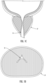
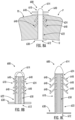
- FIGS. 1A and 1B illustrate the prostate P and the urethra U of a patient having normal anatomy.
- FIGS. 1C and 1D illustrate the prostate P and the urethra U of a patient having BPH.
- BPH involves a narrowing of the urethra, which may result in LUTS such as frequent urination, urge incontinence, increased frequency of urination at night, and a weak stream with difficulty starting urination.
- LUTS such as frequent urination, urge incontinence, increased frequency of urination at night, and a weak stream with difficulty starting urination.
- the implantable devices may be implanted in an outpatient setting, without the need for general anesthesia or an overnight hospital stay, and may provide rapid, effective, and durable relief from LUTS caused by BPH.
- the implantable devices may be implanted in a minimally-invasive manner.
- the implantable devices may address one or more of the above-mentioned problems associated with existing devices and their use.
- some embodiments of the implantable devices may be easily removable post-deployment, if needed.
- the implantable devices may be capable of adjusting or dialing-in an appropriate level of tissue retraction to meet a patient's specific needs.
- the implantable devices may be MR safe and may reduce the overall procedure time for implantation.
- the implantable devices may be implanted with a reloadable delivery system that allows multiple implantable devices to be easily deployed during a procedure, thereby improving user experience and making the system more cost-effective.
- the implantable devices described herein may improve the ease, effectiveness, and economics of using the devices, making the devices more suitable for both developed and emerging economies, and potentially improving the clinical effect and durability of the therapy. Additionally, the tissue-sparing and removable attributes of the implantable devices would not preclude their use in patients that may continue with medical management or elect to have additional minimally-invasive or surgical BPH therapies at a later time. Ultimately, the implantable devices may provide faster, sustained relief of LUTS without the side-effects of drugs or surgical options. Still other benefits and advantages of the implantable devices provided herein over conventional devices and techniques will be appreciated by those of ordinary skill in the art from the following description and the appended drawings.
- the device may include a proximal balloon that is configured to reside in the urethra, a distal balloon that is configured to reside outside of the prostatic capsule, and an intermediate balloon that is configured to reside between the distal balloon and the proximal balloon.
- a proximal balloon that is configured to reside in the urethra
- a distal balloon that is configured to reside outside of the prostatic capsule
- an intermediate balloon that is configured to reside between the distal balloon and the proximal balloon.
- Example materials may include nitinol, PEEK, Pebax, stainless steel, and PTFE, although other biocompatible materials may be used.
- a tubular shaft and at least one fluid lumen may connect the balloons. After filling the balloons, the lumen(s) may be sealed by an elastomeric material or a mechanical crimp.
- such a delivery system may have a scope channel built into it so that implantation could be visualized.
- the scope and sheath may be advanced to the area of the prostatic urethra where the device is to be implanted to retract tissue.
- the obturator or cannula then may be advanced out of the tip of the delivery device and into the prostate, creating the channel in the prostate from the urethra to the prostate capsule into which the device is inserted.
- the balloon-style implantable device advantageously may provide the ability to adjust the expanded device to a patient's anatomy to create optimal tissue retraction, ease of implant removal post implantation, low metal content and MR safety attributes, and/or reloadability of the delivery system in situ (i.e., a new delivery system does not need to be placed for each implantable device in the case where multiple devices are to be implanted).
- implantable devices such as balloon-style implantable devices, locking-tab-style implantable devices, movable-barb-style implantable devices, hydraulic-style implantable devices, deformable-style implantable devices, and jack-style implantable devices, and methods of implanting the same will be appreciated from the example devices depicted in the drawings and described below.
- an example implantable device 100 (which also may be referred to as a "prostatic tissue retractor,” a “tissue retractor,” or simply a “device”) is depicted.
- the implantable device 100 is configured for retracting prostatic tissue PT of a patient to treat LUTS caused by BPH.
- the device 100 may be implanted in a minimally-invasive manner.
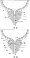
- An example placement of the implantable device 100 is depicted in FIG. 2A .
- multiple devices 100 may be used for a single patient.
- the implantable device 100 generally may include a shaft 110 and a plurality of balloons.
- the device 100 may include a proximal balloon 120, a distal balloon 130, and an intermediate balloon 140, as shown in FIG. 2A .
- the shaft 110 may have a proximal end 112 and a distal end 114 disposed opposite one another in a direction of a longitudinal axis of the shaft 110.
- the shaft 110 may be formed of a flexible material and at least a portion of the shaft 110 may be configured to be elastically deformed from a natural undeformed configuration to a deformed configuration.
- Example materials may include nitinol, PEEK, Pebax, stainless steel, and PTFE, although other biocompatible materials may be used.
- the shaft 110 may have a linear shape when the shaft 110 is in the natural undeformed configuration. In some embodiments, the shaft 110 may have a curved or otherwise contoured shape when the shaft 110 is in the natural undeformed configuration. As shown, the shaft 110 may be configured to extend through prostatic tissue PT of the patient.
- the proximal balloon 120 may be fixedly attached to the shaft 110 and positioned closer to the proximal end 112 than the distal end 114. In some embodiments, the proximal balloon 120 may be positioned at the proximal end 112 of the shaft 110. The proximal balloon 120 may be configured to reside within the prostatic urethra U of the patient. In some embodiments, as shown, the proximal balloon 120 may be configured to contact the wall of the prostatic urethra U when the device 100 is in an implanted state. The proximal balloon 120 may be expandable from an unexpanded configuration to an expanded configuration, for example, by filling a reservoir of the proximal balloon 120 with a fluid.
- the distal balloon 130 may be fixedly attached to the shaft 110 and positioned closer to the distal end 114 than the proximal end 112. In some embodiments, the distal balloon 130 may be positioned at the distal end 114 of the shaft 110. The distal balloon 130 may be configured to reside outside of the prostatic capsule PC of the patient. The distal balloon 130 may be expandable from an unexpanded configuration to an expanded configuration, for example, by filling a reservoir of the distal balloon 130 with a fluid.
- the intermediate balloon 140 may be fixedly attached to the shaft and positioned between the proximal balloon 120 and the distal balloon 130. In some embodiments, as shown, the intermediate balloon 140 may be positioned closer to the distal balloon 130 than the proximal balloon 120. In some embodiments, the intermediate balloon 140 may be positioned adjacent to the distal balloon 130.
- the intermediate balloon 140 may be configured to reside outside of the prostatic capsule PC of the patient. In some embodiments, as shown, the intermediate balloon 140 may be configured to contact the prostatic capsule PC when the device 100 is in an implanted state.
- the intermediate balloon 140 may be expandable from an unexpanded configuration to an expanded configuration, for example, by filling a reservoir of the intermediate balloon 140 with a fluid.
- the proximal balloon 120 may have a length in the direction of the longitudinal axis when the proximal balloon 120 is in the expanded configuration, and the diameter of the balloon 120 may be greater than the length. In this manner, the obstruction of the urethra lumen by the proximal balloon 120 may be minimized.
- the distal balloon 130 when in its expanded configuration, may have an outer diameter (in the direction perpendicular to the longitudinal axis) that is greater than the diameter of the shaft 110. In this manner, after insertion of the shaft 110 through the channel, the distal balloon 130 may be expanded to inhibit the balloon 130 from entering the channel, thereby securing placement of the device 100.
- the intermediate balloon 140 When in its expanded configuration, the intermediate balloon 140 may have an outer diameter (in the direction perpendicular to the longitudinal axis) that is greater than the diameter of the shaft 110. In this manner, the expanded configuration of the intermediate balloon 140 also may inhibit the balloon 140 form entering the channel. In some embodiments, the intermediate balloon 140 may have a length in the direction of the longitudinal axis when the intermediate balloon 140 is in the expanded configuration, and the diameter of the balloon 140 may be less than the length. As discussed further below, expansion of the intermediate balloon 140 may cause retraction of the prostatic tissue PT disposed between the intermediate balloon 140 and the proximal balloon 120. In some embodiments, a degree of expansion of the intermediate balloon 140 may correspond to a degree of retraction of the prostatic tissue PT.
- the lumens 142, 144 of the device 100 may be sealed such that the balloons 120, 130, 140 are maintained in their respective expanded configurations.
- the device 100 may include one or more self-sealing ports 116 for sealing the respective ends of the lumens 142, 144, as shown in FIG. 2B .
- the self-sealing ports 116 may be provided at or near the proximal end 112 of the device 100.
- a first self-sealing port 116 may be provided for the first lumen 142
- a second self-sealing port 116 may be provided for the second lumen 144.
- Each self-sealing port 116 may include an elastomeric member that is configured to be moved between an open configuration for filling the balloons 120, 130, 140 via the respective lumens 142, 144 and a closed configuration for sealing the lumens 142, 144 to maintain the balloons 120, 130, 140 in their expanded configurations.
- the elastomeric members may be formed as one-way valves.
- the lumens 142, 144 of the device 100 may be sealed by a mechanical crimp 118, as shown in FIG. 2C , such that the balloons 120, 130, 140 are maintained in their respective expanded configurations.
- proximal balloon 120 may be omitted, and securement of the device 100 at its proximal end may be provided by a flange, tab or similar structure, or the self-sealing ports 116 that are used for expanding the balloons 130, 140.
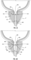
- the shaft 110 may be positioned within the prostatic tissue PT
- the proximal balloon 120 may be positioned within the prostatic urethra U
- the distal balloon 130 and the intermediate balloon 140 may be positioned outside of the prostatic capsule PC.
- the distal balloon 130 and the intermediate balloon 140 may be passed through the prostatic tissue PT while the distal balloon 130 is in its collapsed configuration and the intermediate balloon 140 is in its collapsed configuration.
- the proximal balloon 120 also may be in its collapsed configuration while the device 100 is passed through the prostatic tissue PT.
- the device 100 may be positioned within the cannula 220 such that the device 100 is passed through the prostatic tissue PT while the cannula 220 forms the channel, and then the cannula 220 may be retracted such that the device 100 is deployed in the prostatic tissue PT.
- the obturator or cannula 220 may not be used to form the channel, and the device 100 may be passed directly into the prostatic tissue PT and positioned in the prostate P.
- the proximal balloon 120 and the distal balloon 130 may be expanded, as shown in FIG. 3C . As described above, expansion of the proximal balloon 120 and the distal balloon 130 may secure the device 100 relative to the prostatic tissue PT.
- the proximal balloon 120 and the distal balloon 130 may be expanded while the intermediate balloon 140 is maintained in its collapsed configuration.
- the proximal balloon 120 and the distal balloon 130 may be expanded simultaneously, for example, via a common lumen.
- the intermediate balloon 140 may be expanded, as shown in FIG. 3D .
- FIG. 3E shows the device 100 in an implanted state, after removal of the delivery system.
- the expansion of the intermediate balloon 140 may cause the prostatic tissue PT to be compressed between the proximal balloon 120 and the intermediate balloon 140.
- the implantable device 100 may retract the prostatic tissue PT of the patient to address LUTS caused by BPH.
- a single device 100 may be used.
- multiple devices 100 may be implanted within different portions of prostatic tissue PT of a patient.
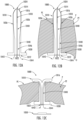
- FIG. 4 illustrates another example implantable device 300 (which also may be referred to as a "prostatic tissue retractor,” a “tissue retractor,” or simply a “device”) having a balloon-style configuration.
- the implantable device 300 generally may be configured in a manner similar to the implantable device 100 described above.
- corresponding features are identified using corresponding reference numbers.
- the device 300 may include a shaft 310 having a proximal end 312 and a distal end 314, a self-sealing port 316, a proximal balloon 320, and a distal balloon 330.
- the device 300 may not include an intermediate balloon.
- the device 300 may include a first lumen 342 that is in fluid communication with the reservoir of the proximal balloon 320 and in fluid isolation from the reservoir of the distal balloon 330, and a second lumen 344 that is in fluid communication with the reservoir of the distal balloon 330 and in fluid isolation from the reservoir of the proximal balloon 320.
- the balloons 320, 330 may be separately expanded, and a degree of expansion of the distal balloon 330 may be adjusted to accommodate the anatomy of a particular patient.
- proximal balloon 320 may be omitted, and securement of the device 300 at its proximal end may be provided by a flange, tab or similar structure, or the self-sealing port 316 that is used for expanding the distal balloon 330.
- the implantable device 300 may be implanted using a method similar to that described above with respect to the implantable device 100.
- an obturator or cannula may be used to form a channel through prostatic tissue PT of the patient, and the device 300 may be passed through the channel such that the device 300 extends from the prostatic urethra U to the prostatic capsule PC.
- the shaft 310 may be positioned within the channel, the proximal balloon 320 may be positioned within the prostatic urethra U, and the distal balloon 330 may be positioned outside of the prostatic capsule PC.
- the obturator or cannula may not be used, and the device 300 may be passed directly into the prostatic tissue PT and positioned.
- the proximal balloon 320 may be expanded to inhibit distal movement of the device 300 relative to the prostatic tissue PT.
- the distal balloon 330 may be expanded to secure the device 300 relative to the prostatic tissue PT and to cause the prostatic tissue PT to be compressed between the proximal balloon 320 and the distal balloon 330.
- the implantable device 300 may retract the prostatic tissue PT of the patient to address LUTS caused by BPH.
- a single device 300 may be used.
- multiple devices 300 may be implanted within different portions of prostatic tissue PT of a patient.
- an example implantable device 400 (which also may be referred to as a "prostatic tissue retractor,” a “tissue retractor,” or simply a “device”) is depicted.
- the implantable device 400 is configured for retracting prostatic tissue PT of a patient to treat LUTS caused by BPH.
- the device 400 may be implanted in a minimally-invasive manner.
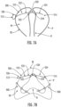
- An example placement of the implantable device 400 is depicted in FIGS. 6E and 6F .
- multiple devices 400 may be used for a single patient, as shown in FIG. 6F .
- the implantable device 400 generally may include a shaft 410 and a plurality of locking tabs.
- the device 400 may include a first locking tab 432 that is movably attached to the shaft 410 and a second locking tab 434 that is movably attached to the shaft 410.
- the shaft 410 may have a first end 412 and a second end 414 disposed opposite one another in a direction of a longitudinal axis of the shaft 410.
- the shaft 410 may be formed of a flexible material and at least a portion of the shaft 410 may be configured to be elastically deformed from a natural undeformed configuration to a deformed configuration.
- Example materials may include nitinol, PEEK, Pebax, stainless steel, and PTFE, although other biocompatible materials may be used.
- the shaft 410 may have a curved shape when the shaft 410 is in the natural undeformed configuration. In other examples, the shaft 410 may have an otherwise contoured shape or may have a linear shape when the shaft 410 is in the natural undeformed configuration. In some examples, shaft 410 may have a circular cross-sectional shape. In other examples, shaft 410 may have a non-circular cross-sectional shape (e.g., triangular, hexagonal, flat).
- the shaft 410 may include a central portion 420 positioned between the first end 412 and the second end 414, a first end portion 422 extending from the central portion 420 to the first end 412, and a second end portion 424 extending from the central portion 420 to the second end 414.
- the central portion 420 may be configured to reside within the prostatic urethra U of the patient.
- the first end portion 422 may be configured to reside at least partially within first prostatic tissue PT of the patient, while the second end portion 424 may be configured to reside at least partially within second prostatic tissue PT of the patient disposed opposite the first prostatic tissue PT.
- the first end portion 422 may include a plurality of first protrusions or recesses 426 configured for engaging the first locking tab 432.
- the second end portion 424 may include a plurality of second protrusions or recesses 428 configured for engaging the second locking tab 434.
- the first protrusions or recesses 426 and the second protrusions or recesses 428 may include annular protrusions each extending around a circumference of the shaft 410.
- the first protrusions or recesses 426 and the second protrusions or recesses 428 may include annular recesses each extending around a circumference of the shaft 410.
- first protrusions or recesses 426 and the second protrusions or recesses 428 may include teeth positioned along a circumference of the shaft 410.
- the central portion 420 may be devoid of any protrusions or recesses.
- the shaft 410 may include a first tip positioned at the first end 412 and configured to pierce the first prostatic tissue PT, and a second tip positioned at the second end 414 and configured to pierce the second prostatic tissue PT.
- Various tip configurations for the first end 412 and the second end 414 may be used, including sharpened tips, blunt tips, square tips, rounded tips, or atraumatic tips.
- the first locking tab 432 may be configured to reside within the prostatic urethra U and to contact the first prostatic tissue PT.
- the second locking tab 434 may be configured to reside within the prostatic urethra U and to contact the second prostatic tissue PT.
- the first protrusions or recesses 426 may be configured to allow the first locking tab 432 to move along the first end portion 422 toward the first end 412 and to inhibit movement of the first locking tab 432 along the first end portion 422 toward the second end 414. In this manner, the engagement between the first locking tab 432 and the first protrusions or recesses 426 may provide a mechanism for one-way movement of the first locking tab 432 toward the first end 412.
- the barbs 640 may be integrally formed with the main body 610 and configured to be elastically deformed or deflected relative to the main body 610.
- the barbs 640 may be separately formed from the main body 610 but attached to the main body 610 and configured to be elastically deformed or deflected relative to the main body 610.
- the barbs 640 may extend through respective openings defined in the main body 610, with each of the barbs 640 including a base portion positioned within the main body 610 and a free end portion positioned outside of the main body 610.
- the implantable device 600 also may include a central pin 650, as shown in FIGS. 8B and 8C .
- the central pin 650 may be removably positioned within the main body 610 and configured to inhibit movement of the barbs 640 inward toward the longitudinal axis of the main body 610 when the central pin 650 is positioned within the main body 610. In some instances, the central pin 650 may be removed from the main body 610 to allow the barbs 640 to move inward relative to the main body 610, for example to ease removal of the device 600 from a patient. In some examples, the central pin 650 may be removably attached to the main body 610, for example by a threaded connection or other means of releasable mechanical attachment.
- the implantable device 600 may be implanted using a method generally similar to that described above with respect to the implantable device 100.
- the device 600 may be implanted using a delivery system under visualization with a cystoscope, as described above.
- a sheath may be inserted through the urethra U of the patient and positioned about the prostate P.
- the device 600 may be passed through a working lumen of the sheath, along with other components of the delivery system to facilitate positioning and deployment of the device 600 under visualization through a cystoscope lumen of the sheath.
- an obturator or cannula may be used to form a channel through prostatic tissue PT of the patient, with the channel extending from the prostatic urethra U to the prostatic capsule PC of the patient.
- one or more of the barbs 640 may be positioned outside of the prostatic capsule PC, while other barbs 640 may be positioned within the prostatic tissue PT. In some examples, all of the barbs 640 may be positioned within the prostatic tissue PT. As shown, the flange 630 may be positioned within the prostatic urethra U and in contact with the prostatic tissue PT. In this manner, the prostatic tissue PT may be compressed between the flange 630 and the barbs 640. Thus, the implantable device 600 may retract the prostatic tissue PT of the patient to address LUTS caused by BPH.
- the extent to which the barbs 640 are advanced into and/or through the prostatic tissue PT may be selected to achieve a desired degree of retraction of the prostatic tissue PT for a particular patient.
- a single device 600 may be used.
- multiple devices 600 may be implanted within different portions of prostatic tissue PT of a patient.
- FIG. 9 illustrates another example implantable device 700 (which also may be referred to as a "prostatic tissue retractor,” a “tissue retractor,” or simply a “device”) having barbs.
- the implantable device 700 generally may be configured in a manner similar to the implantable device 600 described above.
- corresponding features are identified using corresponding reference numbers.
- the device 700 may include a main body 710 having a proximal end 712, a distal end 714, a proximal end portion 722, and a distal end portion 724.
- the device 700 also may include a flange 730, a plurality of barbs 740, and a central pin 750.
- the barbs 740 of the device 700 may be pivotally attached to the main body 710 and configured to pivot relative to the main body 710 from a first configuration to a second configuration, such as when the barbs 740 are advanced into or through the prostatic tissue PT.
- adjacent portions of the main body 710 may be configured to limit a range of pivotal movement of the respective barbs 740 relative to the main body 710. In this manner, the main body 710 may limit pivotal movement of the barbs 740 in an outward direction as well as in an inward direction.
- the implantable device 700 may be implanted using a method similar to that described above with respect to the implantable device 600.
- implantable device 800 (which also may be referred to as a "prostatic tissue retractor,” a “tissue retractor,” or simply a “device”) is depicted.
- the implantable device 800 is configured for retracting prostatic tissue PT of a patient to treat LUTS caused by BPH.
- the device 800 may be implanted in a minimally-invasive manner.
- multiple devices 800 may be used for a single patient.
- the implantable device 800 generally may include a distal body 810, a plurality of barbs 816 extending outwardly from the distal body 810, a proximal body 820, an intermediate body 830 extending between the distal body 810 and the proximal body 820, and a tether 840 extending between the distal body 810 and the proximal body 820.
- the distal body 810 may have a proximal end 812 and a distal end 814 disposed opposite one another in a direction of a longitudinal axis of the distal body 810.
- the distal body 810 may be rigid.
- the distal body 810 may be formed of a flexible material and at least a portion of the distal body 810 may be configured to be elastically deformed from a natural undeformed configuration to a deformed configuration.
- Example materials may include nitinol, PEEK, Pebax, stainless steel, polyethylene, polypropylene, polyester, polyamide, and fluoropolymer, although other biocompatible materials may be used.
- the distal body 810 may be configured to extend at least partially through prostatic tissue PT of the patient, with the distal end 814 of the distal body 810 residing either within the prostatic tissue PT or outside of the prostatic capsule PC.
- the proximal body 820 may be configured to reside within the prostatic urethra U of the patient and to contact the prostatic tissue PT.
- the barbs 816 may be disposed along a portion of the distal body 810.
- the barbs 816 may be configured to engage the prostatic tissue PT of the patient.
- Each of the barbs 816 may be configured to move relative to the distal body 810.
- each of the barbs 816 may be fixedly attached to the distal body 810 and configured to be elastically deformed or deflected from a first configuration to a second configuration, such as when the barbs 816 are advanced into or through the prostatic tissue PT.
- the barbs 816 may be integrally formed with the distal body 810 and configured to be elastically deformed or deflected relative to the distal body 810.
- the barbs 816 may be separately formed from the distal body 810 but attached to the distal body 810 and configured to be elastically deformed or deflected relative to the distal body 810. In some examples, the barbs 816 may be separately formed from and pivotally attached to the distal body 810.
- the intermediate body 830 may be fixedly attached to each of the distal body 810 and the proximal body 820, as shown.
- the intermediate body 830 may have a tubular shape that surrounds the tether 840.
- the intermediate body 830 may be formed of a bioerodeable material, such as PLA, PGA, polycaprolactone, or magnesium, and thus may erode over time after implantation of the device 800 within a patient. In this manner, the intermediate body 830 may facilitate implantation of the device 800, maintaining a spacing between and relative orientation of the distal body 810 and the proximal body 820 during implantation.
- the tether 840 may be fixedly attached to each of the distal body 810 and the proximal body 820, as shown.
- the tether 840 may be flexible. In some examples, the tether 840 may be or may include a non-absorbable suture. After erosion of the intermediate body 830, the distal body 810 and the proximal body 820 may remain attached to one another by the tether 840.
- the implantable device 800 may be implanted using a method generally similar to that described above with respect to the implantable device 100.
- the device 800 may be implanted using a delivery system under visualization with a cystoscope, as described above.
- a sheath may be inserted through the urethra U of the patient and positioned about the prostate P.
- the device 800 may be passed through a working lumen of the sheath, along with other components of the delivery system to facilitate positioning and deployment of the device 800 under visualization through a cystoscope lumen of the sheath.
- an obturator or cannula may be used to form a channel through prostatic tissue PT of the patient, with the channel extending from the prostatic urethra U to the prostatic capsule PC of the patient.
- the device 800 may be passed through the prostatic tissue PT without first forming a channel.
- the barbs 816 may be elastically deformed or deflected when the barbs 816 are advanced into or through the prostatic tissue PT.
- the device 800 may be positioned such that the device 800 extends from the prostatic urethra U to the prostatic capsule PC.
- the device 800 may extend through the prostatic tissue PT, with the distal end 814 of the distal body 810 positioned outside of the prostatic capsule PC.
- the device 800 may extend only partially through the prostatic tissue PT, with the distal end 814 of the distal body 810 positioned within the prostatic tissue PT.
- the intermediate body 830 may extend partially through the prostatic tissue PT, and the tether 840 may extend partially through the prostatic tissue PT.
- one or more of the barbs 816 may be positioned outside of the prostatic capsule PC, while other barbs 816 may be positioned within the prostatic tissue PT. In some examples, all of the barbs 816 may be positioned within the prostatic tissue PT.
- the proximal body 820 may be positioned within the prostatic urethra U and in contact with the prostatic tissue PT. In this manner, the prostatic tissue PT may be compressed between the proximal body 820 and the barbs 816.
- the implantable device 800 may retract the prostatic tissue PT of the patient to address LUTS caused by BPH. It will be appreciated that the extent to which the barbs 816 are advanced into and/or through the prostatic tissue PT may be selected to achieve a desired degree of retraction of the prostatic tissue PT for a particular patient. In some examples, a single device 800 may be used. In other examples, multiple devices 800 may be implanted within different portions of prostatic tissue PT of a patient.
- FIG. 11 depicts an example implantable device 900 (which also may be referred to as a "prostatic tissue retractor,” a “tissue retractor,” or simply a “device”) that utilizes a hydraulic mechanism.
- the implantable device 900 is configured for retracting prostatic tissue PT of a patient to treat LUTS caused by BPH.
- the device 900 may be implanted in a minimally-invasive manner.
- multiple devices 900 may be used for a single patient.
- the implantable device 900 generally may include a distal body 910, a plurality of barbs 916 extending outwardly from the distal body 910, a proximal body 920, and a flange 930.
- the distal body 910 may have a proximal end 912 and a distal end 914 disposed opposite one another in a direction of a longitudinal axis of the distal body 910.
- the distal body 910 may be rigid.
- the distal body 910 may be formed of a flexible material.
- Example materials may include nitinol, PEEK, Pebax, stainless steel, polyethylene, polypropylene, polyester, polyamide, and fluoropolymer, although other biocompatible materials may be used.
- the distal body 910 may be configured to extend at least partially through prostatic tissue PT of the patient, with the distal end 914 of the distal body 910 residing either within the prostatic tissue PT or outside of the prostatic capsule PC.
- the proximal body 920 may have a proximal end 922 and a distal end 924 disposed opposite one another in a direction of a longitudinal axis of the proximal body 920.
- the proximal body 920 may be rigid.
- the proximal body 920 may be formed of a flexible material.
- Example materials may include nitinol, PEEK, Pebax, stainless steel, polyethylene, polypropylene, polyester, polyamide, and fluoropolymer, although other biocompatible materials may be used.
- the proximal body 920 may be configured to extend at least partially through prostatic tissue PT of the patient, with the distal end 924 of the proximal body 920 residing within the prostatic tissue PT and the proximal end 922 residing within the prostatic urethra U of the patient.
- the flange 930 may be fixedly attached to the proximal body 920 at the proximal end 922 thereof. In this manner, the flange 930 may be configured to reside within the prostatic urethra U of the patient and to contact the prostatic tissue PT.
- the barbs 916 may be disposed along a portion of the distal body 910.
- the barbs 916 may be configured to engage the prostatic tissue PT of the patient.
- Each of the barbs 916 may be configured to move relative to the distal body 910.
- the barbs 916 may be separately formed from the distal body 910 but attached to the distal body 910 and configured to pivot relative to the distal body 910.
- the barbs 916 may be separately formed from the distal body 910 but attached to the distal body 910 and configured to be elastically deformed or deflected relative to the distal body 910.
- the barbs 916 may be integrally formed with the distal body 910 and configured to be elastically deformed or deflected relative to the distal body 910.
- the distal body 910 may define a reservoir within the distal body 910.
- the proximal body 920 similarly may define a reservoir within the proximal body 920 and in fluid communication with the reservoir of the distal body 910.
- a fluid 950 may be contained within the reservoirs of the distal body 910 and the proximal body 920.
- the fluid 950 may include any suitable biocompatible, noncompressible fluids, such as saline, water, adhesives, acrylics, epoxies, or polymethylmethacrylate.
- the device 900 may include a port 932 positioned at the proximal end 922 of the proximal body 920 and in fluid communication with the reservoirs of the distal body 910 and the proximal body 920.
- the port 932 may facilitate withdrawal of a portion of the fluid 950 from the reservoirs of the distal body 910 and the proximal body 920 during implantation of the device 900.
- the port 932 may include a valve, such as a self-sealing valve.
- the proximal body 920 may be translatably attached to the distal body 910.
- the proximal body 920 may be configured to translate relative to the distal body 910 from an extended configuration to a retracted configuration. Specifically, the proximal body 920 may be configured to translate relative to the distal body 910 from an extended configuration to a retracted configuration when a portion of the fluid 950 is withdrawn from the reservoirs of the distal body 910 and the proximal body 920 via the port 932. As shown, the device 900 may include a seal 940 positioned at an interface between the distal body 910 and the proximal body 920 to prevent leakage of the fluid 950 therebetween.
- the implantable device 900 may be implanted using a method generally similar to that described above with respect to the implantable device 100.
- the device 900 may be implanted using a delivery system under visualization with a cystoscope, as described above.
- a sheath may be inserted through the urethra U of the patient and positioned about the prostate P.
- the device 900 may be passed through a working lumen of the sheath, along with other components of the delivery system to facilitate positioning and deployment of the device 900 under visualization through a cystoscope lumen of the sheath.
- an obturator or cannula may be used to form a channel through prostatic tissue PT of the patient, with the channel extending from the prostatic urethra U to the prostatic capsule PC of the patient.
- the device 900 may be passed through the prostatic tissue PT without first forming a channel.
- the barbs 916 may pivot or may be elastically deformed or deflected when the barbs 916 are advanced into or through the prostatic tissue PT.
- the device 900 may be positioned such that the device 900 extends from the prostatic urethra U to the prostatic capsule PC.
- the device 900 may extend through the prostatic tissue PT, with the distal end 914 of the distal body 910 positioned outside of the prostatic capsule PC. In some examples, the device 900 may extend only partially through the prostatic tissue PT, with the distal end 914 of the distal body 910 positioned within the prostatic tissue PT. In some examples, one or more of the barbs 916 may be positioned outside of the prostatic capsule PC, while other barbs 916 may be positioned within the prostatic tissue PT. In some examples, all of the barbs 816 may be positioned outside of the prostatic capsule PC. In some examples, all of the barbs 816 may be positioned within the prostatic tissue PT.
- the proximal body 920 may be positioned partially within the prostatic tissue PT and partially within the prostatic urethra U.
- the flange 930 may be positioned within the prostatic urethra U and in contact with the prostatic tissue PT.
- a portion of the fluid 950 may be withdrawn from the reservoirs of the distal body 910 and the proximal body 920 via the port 932 such that the proximal body 920 translates relative to the distal body 910 from an extended configuration to a retracted configuration. In this manner, the prostatic tissue PT may be compressed between the flange 930 and the barbs 916.
- the implantable device 900 may retract the prostatic tissue PT of the patient to address LUTS caused by BPH. It will be appreciated that the amount of fluid 950 that is withdrawn may be selected to achieve a desired degree of retraction of the prostatic tissue PT for a particular patient. In some examples, a single device 900 may be used. In other examples, multiple devices 900 may be implanted within different portions of prostatic tissue PT of a patient.
- FIGS. 12A-12C depict an example implantable device 1000 (which also may be referred to as a "prostatic tissue retractor,” a “tissue retractor,” or simply a “device”) that utilizes a deformable or peelable main body.
- the implantable device 1000 is configured for retracting prostatic tissue PT of a patient to treat LUTS caused by BPH.
- the device 1000 may be implanted in a minimally-invasive manner.
- multiple devices 1000 may be used for a single patient.
- the implantable device 1000 generally may include a main body 1010, a flange 1030, and a suture 1040.
- the main body 1010 may have a proximal end 1012 and a distal end 1014 disposed opposite one another in a direction of a longitudinal axis of the main body 1010.
- the main body 1010 may be formed of a deformable or peelable material, such as Pebax, polyethylene, polypropylene, polyester, polyamide, or fluoropolymer, although other suitable materials may be used.
- the main body 1010 may be configured to extend through prostatic tissue PT of the patient, with the distal end 1014 of the main body 1010 residing outside of the prostatic capsule PC and the proximal end 1012 of the main body 1010 residing within the prostatic urethra U.
- the main body 1010 may include a distal end portion 1016 that is configured to reside at least partially outside of the prostatic capsule PC, as shown in FIG. 12B .
- the distal end portion 1016 may be configured to deform from an undeformed configuration, as shown in FIGS. 12A and 12B , to a deformed configuration, as shown in FIG. 12C .
- the suture 1040 may include a first end 1042, a second end 1044, and an intermediate portion 1046 extending between the ends 1042, 1044. As shown, the ends 1042, 1044 may extend from the proximal end 1012 of the main body 1010.
- the suture 1040 may be configured to cause the distal end portion 1016 of the main body 1010 to deform from the undeformed configuration to the deformed configuration when the first end 1042 and the second end 1044 are pulled proximally relative to the main body 1010. As shown, portions of the suture 1040 may extend through the main body 1010, while other portions of the suture 1040 extend along an outer surface of the distal end portion 1016 of the main body 1010.
- the main body 1010 may include a plurality of openings that guide the suture 1040 through and along the main body 1010. As shown, the main body 1010 may include a plurality of proximal openings 1022, a distal opening 1024, and a plurality of side openings 1026.
- the suture 1040 may include a plurality of segments connected in series between the first end 1042 and the second end 1044, with each segment interfacing with different portions of the main body 1010.
- a first segment may extend from the first end 1042 through a first proximal opening 1022 and through the main body 1010 to a first side opening 1026
- a second segment may extend from the first side opening 1026 and along the outer surface of the distal end portion 1016 to the distal opening 1024
- a third segment may extend from the distal opening 1024 through the main body 1010 and through a second proximal opening 1022
- a fourth segment may extend through a third proximal opening 1022 through the main body 1010 and through the distal opening 1024
- a fifth segment may extend from the distal opening 1024 along the outer surface of the distal end portion 1016 to a second side opening 1026
- a sixth segment may extend from the second side opening 1026 through the main body 1010 to the second end 1044.
- the distal end portion 1016 may be deformed from the undeformed configuration to the deformed configuration. Specifically, such pulling of the suture 1040 may cause the distal end portion 1016 to deform radially outward relative to the longitudinal axis of the main body 1010 from the undeformed configuration to the deformed configuration, as shown in FIG. 12C .
- the deformation of the distal end portion 1016 may include separation of respective segments of the distal end portion 1016 from one another.
- the distal end portion 1016 may include one or more zones of weakness 1018 configured to facilitate separation of the respective segments of the distal end portion from one another.
- the zones of weakness 1018 may include perforations defined in the distal end portion 1016.
- the implantable device 1000 may be implanted using a method generally similar to that described above with respect to the implantable device 100.
- the device 1000 may be implanted using a delivery system under visualization with a cystoscope, as described above.
- a sheath may be inserted through the urethra U of the patient and positioned about the prostate P.
- the device 1000 may be passed through a working lumen of the sheath, along with other components of the delivery system to facilitate positioning and deployment of the device 1000 under visualization through a cystoscope lumen of the sheath.
- an obturator or cannula may be used to form a channel through prostatic tissue PT of the patient, with the channel extending from the prostatic urethra U to the prostatic capsule PC of the patient.
- the device 1000 may be passed through the prostatic tissue PT without first forming a channel.
- the device 1000 may extend through the prostatic tissue PT, with the distal end 1014 of the main body 1010 positioned outside of the prostatic capsule PC.
- the distal end portion 1016 may be positioned outside of the prostatic capsule PC.
- the flange 1030 may be positioned within the prostatic urethra U and in contact with the prostatic tissue PT.
- the distal end portion 1016 may be deformed from an undeformed configuration to a deformed configuration by pulling the ends 1042, 1044 of the suture 1040 proximally relative to the main body 1010.
- the implantable device 1000 may retract the prostatic tissue PT of the patient to address LUTS caused by BPH.
- the extent of deformation of the distal end portion 1016 may be selected to achieve a desired degree of retraction of the prostatic tissue PT for a particular patient.
- the free end portions of the suture 1040 may be secured relative to the main body 1010.
- a cap 1050 may be used to secure the free end portions of the suture 1040 to the main body 1010 and/or the flange 1030.
- the free end portions of the suture 1040 may be tied into knots. In some examples, the free end portions of the suture 1040 may secured by an additional capture mechanism of the device 1000. In some examples, the free end portions of the suture 1040 may be cut off or otherwise removed after securing or tying. In some examples, a single device 1000 may be used. In other examples, multiple devices 1000 may be implanted within different portions of prostatic tissue PT of a patient.
- FIGS. 13A and 13B illustrate another example implantable device 1100 (which also may be referred to as a "prostatic tissue retractor,” a “tissue retractor,” or simply a “device”) having a jack-style configuration.
- the implantable device 1100 is configured for retracting prostatic tissue PT of a patient to treat LUTS caused by BPH.
- the device 1100 may be implanted in a minimally-invasive manner.
- An example placement of the implantable device 1100 is depicted in FIG. 13B .
- multiple devices 1100 may be used for a single patient.
- the implantable device 1100 generally may include a distal body 1110, a plurality of barbs 1116 extending outwardly from the distal body 1110, a proximal body 1120, a shaft 1130 movably attached to each of the distal body 1110 and the proximal body 1120, and two pairs of link arms 1140 extending between the distal body 1110 and the proximal body 1120.
- the distal body 1110 and the proximal body 1120 each may be formed as plate-like members positioned at opposite ends of the device 1100, although other shapes and configurations of the distal body 1110 and the proximal body 1120 may be used in other examples.
- the distal body 1110 and the proximal body 1120 may be rigid. In some examples, the distal body 1110 and the proximal body 1120 may be formed of a flexible material and at least portions of the distal body 1110 and the proximal body 1120 may be configured to be elastically deformed from a natural undeformed configuration to a deformed configuration.
- Example materials may include nitinol, PEEK, Pebax, stainless steel, polyethylene, polypropylene, polyester, polyamide, and fluoropolymer, although other biocompatible materials may be used.
- the distal body 1110 may be configured to reside outside of the prostatic capsule PC of the patient, and the proximal body 1120 may be configured to reside within the prostatic urethra U of the patient and to contact the prostatic tissue PT.
- the barbs 1116 may be attached to the distal body 1110 and may extend outwardly therefrom.
- the barbs 1116 may be configured to engage the prostatic capsule PC or the prostatic tissue PT of the patient.
- Each of the barbs 1116 may be configured to move relative to the distal body 1110.
- each of the barbs 1116 may be pivotally attached to the distal body 1110 via respective hinges 1118 and configured to pivot from a first configuration to a second configuration, such as when the barbs 1116 are advanced into or through the prostatic tissue PT.
Landscapes
- Health & Medical Sciences (AREA)
- Life Sciences & Earth Sciences (AREA)
- Surgery (AREA)
- Molecular Biology (AREA)
- Engineering & Computer Science (AREA)
- Biomedical Technology (AREA)
- Heart & Thoracic Surgery (AREA)
- Medical Informatics (AREA)
- Nuclear Medicine, Radiotherapy & Molecular Imaging (AREA)
- Animal Behavior & Ethology (AREA)
- General Health & Medical Sciences (AREA)
- Public Health (AREA)
- Veterinary Medicine (AREA)
- Rheumatology (AREA)
- Prostheses (AREA)
- Surgical Instruments (AREA)
Claims (15)
- Implantierbare Vorrichtung (100) zur Retraktion von Prostatagewebe eines Patienten, umfassend:einen Schaft (110) mit einem proximalen Ende (112) und einem distalen Ende (114), die sich in Richtung seiner Längsachse gegenüberliegen, gekennzeichnet durcheinen proximalen Ballon (120), der fest an dem Schaft (110) angebracht ist, wobei der proximale Ballon (120) näher am proximalen Ende (112) als am distalen Ende (114) angeordnet ist,einen distalen Ballon (130), der fest an dem Schaft (110) angebracht ist, wobei der distale Ballon (130) näher am distalen Ende (114) als am proximalen Ende (112) angeordnet ist, undeinen Zwischenballon (140), der fest an dem Schaft (110) angebracht ist, wobei der Zwischenballon (140) zwischen dem proximalen Ballon (120) und dem distalen Ballon (130) angeordnet ist,wobei der Schaft (110) ein erstes Lumen (142) definiert, das mit einem ersten Reservoir des proximalen Ballons (120) und einem zweiten Reservoir des distalen Ballons (130) in Fließverbindung steht und fluidisch von einem dritten Reservoir, das durch den Zwischenballon (140) definiert wird, isoliert ist.
- Implantierbare Vorrichtung (100) nach Anspruch 1, wobei sich der proximale Ballon (120) am proximalen Ende (112) des Schafts (110) und der distale Ballon (130) am distalen Ende (114) des Schafts (110) befindet.
- Implantierbare Vorrichtung (100) nach einem der vorhergehenden Ansprüche, wobei sich der Zwischenballon (140) näher am distalen Ballon (130) als am proximalen Ballon (120) befindet.
- Implantierbare Vorrichtung (100) nach einem der vorhergehenden Ansprüche, wobei der Schaft (110) ferner ein zweites Lumen (144) umfasst, das mit dem dritten Reservoir des Zwischenballons (140) in Fließverbindung steht und vom ersten Reservoir des proximalen Ballons (120) und vom zweiten Reservoir des distalen Ballons (130) fluidisch isoliert ist.
- Implantierbare Vorrichtung (100) nach einem der vorhergehenden Ansprüche, wobei der Schaft (110) einen ersten Durchmesser senkrecht zur Längsachse aufweist, der proximale Ballon (120) in eine expandierte Konfiguration expandierbar ist, in welcher der proximale Ballon (120) einen zweiten Durchmesser senkrecht zur Längsachse aufweist und der zweite Durchmesser größer als der erste Durchmesser ist.
- Implantierbare Vorrichtung (100) nach Anspruch 5, wobei der proximale Ballon (120) in expandierter Konfiguration eine Länge in Richtung der Längsachse aufweist und der zweite Durchmesser größer als die Länge ist.
- Implantierbare Vorrichtung (100) nach einem der vorhergehenden Ansprüche, wobei der Schaft (110) einen ersten Durchmesser senkrecht zur Längsachse aufweist, der distale Ballon (130) in eine expandierte Konfiguration expandierbar ist, in welcher der distale Ballon (130) einen zweiten Durchmesser senkrecht zur Längsachse aufweist und der zweite Durchmesser größer als der erste Durchmesser ist.
- Implantierbare Vorrichtung (100) nach Anspruch 7, wobei der distale Ballon (130) in expandierter Konfiguration eine Länge in Richtung der Längsachse aufweist und der zweite Durchmesser größer als die Länge ist.
- Implantierbare Vorrichtung (100) nach einem der vorhergehenden Ansprüche, wobei der Schaft (110) einen ersten Durchmesser senkrecht zur Längsachse aufweist, der Zwischenballon (140) in eine expandierte Konfiguration expandierbar ist, in welcher der Zwischenballon (140) einen zweiten Durchmesser senkrecht zur Längsachse aufweist und der zweite Durchmesser größer als der erste Durchmesser ist.
- Implantierbare Vorrichtung (100) nach Anspruch 9, wobei der Zwischenballon (140) in expandierter Konfiguration eine Länge in Richtung der Längsachse aufweist und der zweite Durchmesser kleiner als die Länge ist.
- Implantierbare Vorrichtung (100) nach einem der vorhergehenden Ansprüche, wobei der Zwischenballon selektiv expandierbar ist, um den Grad der Retraktion des Prothesengewebes anzupassen.
- Implantierbare Vorrichtung (100) nach Anspruch 4, wobei das erste Lumen (142) und das zweite Lumen (144) verschließbar sind, um den proximalen Ballon (120), den distalen Ballon (130) und den Zwischenballon (140) in der jeweiligen expandierten Konfiguration zu halten.
- Implantierbare Vorrichtung (100) nach Anspruch 12, ferner umfassend eine erste selbstdichtende Öffnung (116) und eine zweite selbstdichtende Öffnung (116), wobei die erste selbstdichtende Öffnung (116) in Fließverbindung mit dem ersten Lumen (142) steht, die zweite selbstdichtende Öffnung (116) in Fließverbindung mit dem zweiten Lumen (144) steht, jede der ersten selbstdichtenden Öffnung (116) und der zweiten selbstdichtenden Öffnung (116) jeweils ein Elastomerelement umfasst, das eine offene und eine geschlossene Konfiguration einnehmen kann, wobei die erste selbstdichtende Öffnung (116) in der geschlossenen Konfiguration den proximalen Ballon (120) und den distalen Ballon (130) in jeweils expandierter Konfiguration hält und die zweite selbstdichtende Öffnung (116) in der geschlossenen Konfiguration den Zwischenballon (140) in expandierter Konfiguration hält.
- Implantierbare Vorrichtung (100) nach Anspruch 13, wobei die erste selbstdichtende Öffnung und die zweite selbstdichtende Öffnung jeweils Einwegventile sind.
- Implantierbare Vorrichtung (100) nach Anspruch 12, ferner umfassend eine mechanische Crimp-Verbindung (118), wobei die mechanische Crimp-Verbindung (118) betätigt werden kann, um das erste Lumen 142 und das zweite Lumen 144 abzudichten und so den proximalen Ballon (120), den distalen Ballon (130) und den Zwischenballon (140) in der jeweiligen expandierten Konfiguration zu halten.
Applications Claiming Priority (2)
| Application Number | Priority Date | Filing Date | Title |
|---|---|---|---|
| US202063005408P | 2020-04-05 | 2020-04-05 | |
| PCT/US2021/025762 WO2021207068A1 (en) | 2020-04-05 | 2021-04-05 | Devices and methods for retracting prostatic tissue of a patient |
Publications (3)
| Publication Number | Publication Date |
|---|---|
| EP4132383A1 EP4132383A1 (de) | 2023-02-15 |
| EP4132383A4 EP4132383A4 (de) | 2024-04-24 |
| EP4132383B1 true EP4132383B1 (de) | 2025-07-02 |
Family
ID=78023475
Family Applications (1)
| Application Number | Title | Priority Date | Filing Date |
|---|---|---|---|
| EP21785710.1A Active EP4132383B1 (de) | 2020-04-05 | 2021-04-05 | Vorrichtungen zur retraktion des prostatagewebes eines patienten |
Country Status (4)
| Country | Link |
|---|---|
| US (1) | US12471912B2 (de) |
| EP (1) | EP4132383B1 (de) |
| CN (1) | CN115884720A (de) |
| WO (1) | WO2021207068A1 (de) |
Families Citing this family (9)
| Publication number | Priority date | Publication date | Assignee | Title |
|---|---|---|---|---|
| US7758594B2 (en) | 2005-05-20 | 2010-07-20 | Neotract, Inc. | Devices, systems and methods for treating benign prostatic hyperplasia and other conditions |
| US10195014B2 (en) | 2005-05-20 | 2019-02-05 | Neotract, Inc. | Devices, systems and methods for treating benign prostatic hyperplasia and other conditions |
| US9504461B2 (en) | 2005-05-20 | 2016-11-29 | Neotract, Inc. | Anchor delivery system |
| US10130353B2 (en) | 2012-06-29 | 2018-11-20 | Neotract, Inc. | Flexible system for delivering an anchor |
| AU2018389236B2 (en) | 2017-12-23 | 2021-05-20 | Teleflex Life Sciences Llc | Expandable tissue engagement apparatus and method |
| WO2020096827A1 (en) | 2018-11-07 | 2020-05-14 | Neotract, Inc. | System for delivery of a fiducial marker |
| EP3876853A1 (de) | 2018-11-08 | 2021-09-15 | Neotract, Inc. | Vorrichtung zur behandlung von blutungen |
| EP4691384A2 (de) | 2020-02-21 | 2026-02-11 | Teleflex Life Sciences LLC | Vorrichtung zur verhinderung von vorrichtungseinsatzfehlern |
| CN114286646B (zh) | 2020-08-03 | 2024-03-08 | 泰利福生命科学有限公司 | 用于医疗干预的手柄和匣盒系统 |
Family Cites Families (39)
| Publication number | Priority date | Publication date | Assignee | Title |
|---|---|---|---|---|
| US1798124A (en) | 1929-08-15 | 1931-03-24 | Josiah Brinkerhoff | Urethral sound and axis-traction prostatic retractor |
| US5030227A (en) | 1988-06-02 | 1991-07-09 | Advanced Surgical Intervention, Inc. | Balloon dilation catheter |
| US6228116B1 (en) | 1987-12-22 | 2001-05-08 | Walter J. Ledergerber | Tissue expander |
| US4932956A (en) | 1988-05-10 | 1990-06-12 | American Medical Systems, Inc. | Prostate balloon dilator |
| US5843156A (en) | 1988-08-24 | 1998-12-01 | Endoluminal Therapeutics, Inc. | Local polymeric gel cellular therapy |
| CA2044867C (en) | 1990-06-25 | 1999-10-12 | James J. Rudnick | Direct vision prostate balloon catheter |
| US5188596A (en) | 1990-09-27 | 1993-02-23 | Mentor Corporation | Transparent prostate dilation balloon and scope |
| US5361752A (en) | 1991-05-29 | 1994-11-08 | Origin Medsystems, Inc. | Retraction apparatus and methods for endoscopic surgery |
| US5383889A (en) | 1991-05-29 | 1995-01-24 | Origin Medsystems, Inc. | Tethered everting balloon retractor for hollow bodies and method of using |
| US5232443A (en) | 1992-07-17 | 1993-08-03 | Leach Gary E | Combined urological retractor and instrument for inserting suprapubic catheter and method of use |
| US5322501A (en) | 1992-10-02 | 1994-06-21 | Mahmud Durrani Ayaz | Continent urethral stent for treating and preventing urethral stricture after surgery |
| US5499994A (en) | 1993-07-30 | 1996-03-19 | American Medical Systems, Inc. | Dilation device for the urethra |
| US5735845A (en) | 1995-01-17 | 1998-04-07 | Uros Corporation | Method of treating the prostate using cryosurgery |
| US5645528A (en) | 1995-06-06 | 1997-07-08 | Urologix, Inc. | Unitary tip and balloon for transurethral catheter |
| US6048309A (en) | 1996-03-04 | 2000-04-11 | Heartport, Inc. | Soft tissue retractor and delivery device therefor |
| EP0929259B1 (de) | 1996-03-20 | 2006-12-06 | General Surgical Innovations, Inc. | Kombinierte dissektion- und retraktionsvorrichtung |
| US6045498A (en) | 1997-06-12 | 2000-04-04 | Uromedica, Inc. | Method for adjustably restricting a body lumen |
| CA2304653C (en) | 1997-10-01 | 2005-07-05 | Srinivas Nishtala | Dilation systems and related methods |
| US6517566B1 (en) | 1998-05-11 | 2003-02-11 | Surgical Connections, Inc. | Devices and methods for treating e.g. urinary stress incontinence |
| US6494879B2 (en) | 1998-10-15 | 2002-12-17 | Scimed Life Systems, Inc. | Treating urinary retention |
| AU5598300A (en) | 1999-10-13 | 2001-04-23 | Jeffrey E. Yeung | Non-invasive and minimally invasive methods and devices for treating urinary incontinence or obstruction |
| US6716252B2 (en) | 2000-06-30 | 2004-04-06 | Wit Ip Corporation | Prostatic stent with localized tissue engaging anchoring means and methods for inhibiting obstruction of the prostatic urethra |
| EP1441798B1 (de) | 2001-10-18 | 2011-12-07 | Abbeymoor Medical, Inc. | Endourethrale vorrichtung |
| US8425539B2 (en) | 2004-04-12 | 2013-04-23 | Xlumena, Inc. | Luminal structure anchoring devices and methods |
| US20060106288A1 (en) | 2004-11-17 | 2006-05-18 | Roth Alex T | Remote tissue retraction device |
| US7758594B2 (en) | 2005-05-20 | 2010-07-20 | Neotract, Inc. | Devices, systems and methods for treating benign prostatic hyperplasia and other conditions |
| US7896891B2 (en) | 2005-05-20 | 2011-03-01 | Neotract, Inc. | Apparatus and method for manipulating or retracting tissue and anatomical structure |
| US9149266B2 (en) | 2005-05-20 | 2015-10-06 | Neotract, Inc. | Deforming anchor device |
| US9549739B2 (en) | 2005-05-20 | 2017-01-24 | Neotract, Inc. | Devices, systems and methods for treating benign prostatic hyperplasia and other conditions |
| US8052710B2 (en) | 2006-12-15 | 2011-11-08 | Parviz Kambin | Endoscopic balloon tissue dissector and retractor |
| WO2009152609A1 (en) * | 2008-06-17 | 2009-12-23 | Antoine Trubiano | Catheter device for the control of liquid discharge from the urinary bladder by a user person |
| AU2009324904B9 (en) * | 2008-11-25 | 2014-07-10 | Lumen Devices Llc | Devices, systems and methods for the treatment of sleep apnea |
| EP2685933B1 (de) | 2011-03-17 | 2019-02-27 | Proarc Medical Ltd. | Vorrichtungen zur behandlung der harnröhre |
| CN106456949B (zh) | 2014-03-14 | 2019-11-01 | 小利兰·斯坦福大学理事会 | 留置体腔扩张器 |
| ES2966897T3 (es) * | 2017-05-05 | 2024-04-24 | Prodeon Medical Corp | Dispositivos y procedimientos de implante para tratar la hiperplasia prostática benigna (HPB) y los síntomas asociados del tracto urinario inferior (STUI) |
| US20210307942A1 (en) | 2018-06-07 | 2021-10-07 | Maurino Galinato Flora | Intraluminal devices for treating benign prostatic hyperplasia |
| US11273025B2 (en) | 2019-11-22 | 2022-03-15 | Pro Verum Limited | Expandable implant delivery device |
| US11602621B2 (en) | 2019-11-22 | 2023-03-14 | ProVerum Limited | Device for controllably deploying expandable implants |
| KR20240054984A (ko) | 2021-08-06 | 2024-04-26 | 리버마크 메디컬, 아이엔씨 | 양성 전립선 비대증 치료용 관내 스텐트 |
-
2021
- 2021-04-05 EP EP21785710.1A patent/EP4132383B1/de active Active
- 2021-04-05 CN CN202180040516.7A patent/CN115884720A/zh active Pending
- 2021-04-05 WO PCT/US2021/025762 patent/WO2021207068A1/en not_active Ceased
-
2022
- 2022-10-04 US US17/959,984 patent/US12471912B2/en active Active
Also Published As
| Publication number | Publication date |
|---|---|
| EP4132383A1 (de) | 2023-02-15 |
| WO2021207068A1 (en) | 2021-10-14 |
| EP4132383A4 (de) | 2024-04-24 |
| CN115884720A (zh) | 2023-03-31 |
| US12471912B2 (en) | 2025-11-18 |
| US20230022482A1 (en) | 2023-01-26 |
Similar Documents
| Publication | Publication Date | Title |
|---|---|---|
| EP4132383B1 (de) | Vorrichtungen zur retraktion des prostatagewebes eines patienten | |
| US12251298B2 (en) | Incising implant for the prostatic urethra | |
| EP1168976B1 (de) | Verabreichungsgerät für submukosale prothesen | |
| EP2313152B1 (de) | Kardiale verankerungsstrukturen | |
| EP3826584B1 (de) | Harnröhrenimplantat | |
| US10035005B2 (en) | Devices for urethral treatment | |
| EP3328317B1 (de) | Retraktion oder/und unterstützung von periurethralem gewebe | |
| JP6130627B2 (ja) | 組織又は解剖学的構造の牽引、持ち上げ、圧縮、支持、又は復位を行うためのデバイス、システム、及び方法 | |
| US20170156865A1 (en) | Treating dysfunctional cardiac tissue | |
| US7185657B1 (en) | Method and device for treating gastroesophageal reflux disease | |
| DE3837779C2 (de) | ||
| WO2002035986A2 (en) | Method and device for treating gastroesophageal reflux disease | |
| EP4599777A1 (de) | Prostatisches harnröhrenimplantat zur behandlung von prostatavergrösserung | |
| WO2025012274A1 (en) | An implant for supporting soft tissue |
Legal Events
| Date | Code | Title | Description |
|---|---|---|---|
| STAA | Information on the status of an ep patent application or granted ep patent |
Free format text: STATUS: THE INTERNATIONAL PUBLICATION HAS BEEN MADE |
|
| PUAI | Public reference made under article 153(3) epc to a published international application that has entered the european phase |
Free format text: ORIGINAL CODE: 0009012 |
|
| STAA | Information on the status of an ep patent application or granted ep patent |
Free format text: STATUS: REQUEST FOR EXAMINATION WAS MADE |
|
| 17P | Request for examination filed |
Effective date: 20221006 |
|
| AK | Designated contracting states |
Kind code of ref document: A1 Designated state(s): AL AT BE BG CH CY CZ DE DK EE ES FI FR GB GR HR HU IE IS IT LI LT LU LV MC MK MT NL NO PL PT RO RS SE SI SK SM TR |
|
| DAV | Request for validation of the european patent (deleted) | ||
| DAX | Request for extension of the european patent (deleted) | ||
| A4 | Supplementary search report drawn up and despatched |
Effective date: 20240326 |
|
| RIC1 | Information provided on ipc code assigned before grant |
Ipc: A61B 17/06 20060101ALN20240320BHEP Ipc: A61B 17/00 20060101ALN20240320BHEP Ipc: A61B 17/064 20060101ALI20240320BHEP Ipc: A61B 17/04 20060101ALI20240320BHEP Ipc: A61B 17/02 20060101ALI20240320BHEP Ipc: A61B 17/12 20060101AFI20240320BHEP |
|
| GRAP | Despatch of communication of intention to grant a patent |
Free format text: ORIGINAL CODE: EPIDOSNIGR1 |
|
| STAA | Information on the status of an ep patent application or granted ep patent |
Free format text: STATUS: GRANT OF PATENT IS INTENDED |
|
| RIC1 | Information provided on ipc code assigned before grant |
Ipc: A61B 17/06 20060101ALN20250129BHEP Ipc: A61B 17/00 20060101ALN20250129BHEP Ipc: A61B 17/064 20060101ALI20250129BHEP Ipc: A61B 17/04 20060101ALI20250129BHEP Ipc: A61B 17/02 20060101ALI20250129BHEP Ipc: A61B 17/12 20060101AFI20250129BHEP |
|
| INTG | Intention to grant announced |
Effective date: 20250211 |
|
| GRAS | Grant fee paid |
Free format text: ORIGINAL CODE: EPIDOSNIGR3 |
|
| GRAA | (expected) grant |
Free format text: ORIGINAL CODE: 0009210 |
|
| STAA | Information on the status of an ep patent application or granted ep patent |
Free format text: STATUS: THE PATENT HAS BEEN GRANTED |
|
| AK | Designated contracting states |
Kind code of ref document: B1 Designated state(s): AL AT BE BG CH CY CZ DE DK EE ES FI FR GB GR HR HU IE IS IT LI LT LU LV MC MK MT NL NO PL PT RO RS SE SI SK SM TR |
|
| REG | Reference to a national code |
Ref country code: GB Ref legal event code: FG4D |
|
| REG | Reference to a national code |
Ref country code: CH Ref legal event code: EP |
|
| REG | Reference to a national code |
Ref country code: DE Ref legal event code: R096 Ref document number: 602021033449 Country of ref document: DE |
|
| REG | Reference to a national code |
Ref country code: IE Ref legal event code: FG4D |
|
| P01 | Opt-out of the competence of the unified patent court (upc) registered |
Free format text: CASE NUMBER: UPC_APP_2353_4132383/2025 Effective date: 20250804 |
|
| REG | Reference to a national code |
Ref country code: NL Ref legal event code: MP Effective date: 20250702 |
|
| PG25 | Lapsed in a contracting state [announced via postgrant information from national office to epo] |
Ref country code: PT Free format text: LAPSE BECAUSE OF FAILURE TO SUBMIT A TRANSLATION OF THE DESCRIPTION OR TO PAY THE FEE WITHIN THE PRESCRIBED TIME-LIMIT Effective date: 20251103 |
|
| PG25 | Lapsed in a contracting state [announced via postgrant information from national office to epo] |
Ref country code: NL Free format text: LAPSE BECAUSE OF FAILURE TO SUBMIT A TRANSLATION OF THE DESCRIPTION OR TO PAY THE FEE WITHIN THE PRESCRIBED TIME-LIMIT Effective date: 20250702 |
|
| REG | Reference to a national code |
Ref country code: AT Ref legal event code: MK05 Ref document number: 1808340 Country of ref document: AT Kind code of ref document: T Effective date: 20250702 |
|
| PG25 | Lapsed in a contracting state [announced via postgrant information from national office to epo] |
Ref country code: IS Free format text: LAPSE BECAUSE OF FAILURE TO SUBMIT A TRANSLATION OF THE DESCRIPTION OR TO PAY THE FEE WITHIN THE PRESCRIBED TIME-LIMIT Effective date: 20251102 |
|
| PG25 | Lapsed in a contracting state [announced via postgrant information from national office to epo] |
Ref country code: NO Free format text: LAPSE BECAUSE OF FAILURE TO SUBMIT A TRANSLATION OF THE DESCRIPTION OR TO PAY THE FEE WITHIN THE PRESCRIBED TIME-LIMIT Effective date: 20251002 |
|
| REG | Reference to a national code |
Ref country code: LT Ref legal event code: MG9D |
|
| PG25 | Lapsed in a contracting state [announced via postgrant information from national office to epo] |
Ref country code: AT Free format text: LAPSE BECAUSE OF FAILURE TO SUBMIT A TRANSLATION OF THE DESCRIPTION OR TO PAY THE FEE WITHIN THE PRESCRIBED TIME-LIMIT Effective date: 20250702 |
|
| PG25 | Lapsed in a contracting state [announced via postgrant information from national office to epo] |
Ref country code: FI Free format text: LAPSE BECAUSE OF FAILURE TO SUBMIT A TRANSLATION OF THE DESCRIPTION OR TO PAY THE FEE WITHIN THE PRESCRIBED TIME-LIMIT Effective date: 20250702 |
|
| PG25 | Lapsed in a contracting state [announced via postgrant information from national office to epo] |
Ref country code: HR Free format text: LAPSE BECAUSE OF FAILURE TO SUBMIT A TRANSLATION OF THE DESCRIPTION OR TO PAY THE FEE WITHIN THE PRESCRIBED TIME-LIMIT Effective date: 20250702 |
|
| PG25 | Lapsed in a contracting state [announced via postgrant information from national office to epo] |
Ref country code: GR Free format text: LAPSE BECAUSE OF FAILURE TO SUBMIT A TRANSLATION OF THE DESCRIPTION OR TO PAY THE FEE WITHIN THE PRESCRIBED TIME-LIMIT Effective date: 20251003 |
|
| PG25 | Lapsed in a contracting state [announced via postgrant information from national office to epo] |
Ref country code: CZ Free format text: LAPSE BECAUSE OF FAILURE TO SUBMIT A TRANSLATION OF THE DESCRIPTION OR TO PAY THE FEE WITHIN THE PRESCRIBED TIME-LIMIT Effective date: 20250702 Ref country code: SE Free format text: LAPSE BECAUSE OF FAILURE TO SUBMIT A TRANSLATION OF THE DESCRIPTION OR TO PAY THE FEE WITHIN THE PRESCRIBED TIME-LIMIT Effective date: 20250702 |
|
| PG25 | Lapsed in a contracting state [announced via postgrant information from national office to epo] |
Ref country code: LV Free format text: LAPSE BECAUSE OF FAILURE TO SUBMIT A TRANSLATION OF THE DESCRIPTION OR TO PAY THE FEE WITHIN THE PRESCRIBED TIME-LIMIT Effective date: 20250702 |
|
| PG25 | Lapsed in a contracting state [announced via postgrant information from national office to epo] |
Ref country code: BG Free format text: LAPSE BECAUSE OF FAILURE TO SUBMIT A TRANSLATION OF THE DESCRIPTION OR TO PAY THE FEE WITHIN THE PRESCRIBED TIME-LIMIT Effective date: 20250702 Ref country code: PL Free format text: LAPSE BECAUSE OF FAILURE TO SUBMIT A TRANSLATION OF THE DESCRIPTION OR TO PAY THE FEE WITHIN THE PRESCRIBED TIME-LIMIT Effective date: 20250702 |
|
| PG25 | Lapsed in a contracting state [announced via postgrant information from national office to epo] |
Ref country code: RS Free format text: LAPSE BECAUSE OF FAILURE TO SUBMIT A TRANSLATION OF THE DESCRIPTION OR TO PAY THE FEE WITHIN THE PRESCRIBED TIME-LIMIT Effective date: 20251002 |
|
| PG25 | Lapsed in a contracting state [announced via postgrant information from national office to epo] |
Ref country code: ES Free format text: LAPSE BECAUSE OF FAILURE TO SUBMIT A TRANSLATION OF THE DESCRIPTION OR TO PAY THE FEE WITHIN THE PRESCRIBED TIME-LIMIT Effective date: 20250702 |