EP4132315B1 - Fastener part - Google Patents
Fastener part Download PDFInfo
- Publication number
- EP4132315B1 EP4132315B1 EP21815492.0A EP21815492A EP4132315B1 EP 4132315 B1 EP4132315 B1 EP 4132315B1 EP 21815492 A EP21815492 A EP 21815492A EP 4132315 B1 EP4132315 B1 EP 4132315B1
- Authority
- EP
- European Patent Office
- Prior art keywords
- crater
- fastener
- depression
- head
- curvature
- Prior art date
- Legal status (The legal status is an assumption and is not a legal conclusion. Google has not performed a legal analysis and makes no representation as to the accuracy of the status listed.)
- Active
Links
- 238000004519 manufacturing process Methods 0.000 claims description 16
- 230000007704 transition Effects 0.000 claims description 12
- 239000000853 adhesive Substances 0.000 claims description 10
- 239000007787 solid Substances 0.000 claims description 2
- 239000000758 substrate Substances 0.000 claims 10
- 239000000463 material Substances 0.000 description 18
- 239000004033 plastic Substances 0.000 description 15
- 229920003023 plastic Polymers 0.000 description 15
- 238000000034 method Methods 0.000 description 13
- 238000000465 moulding Methods 0.000 description 11
- 230000001070 adhesive effect Effects 0.000 description 9
- 238000007493 shaping process Methods 0.000 description 5
- 230000015572 biosynthetic process Effects 0.000 description 4
- 238000000576 coating method Methods 0.000 description 3
- 238000005530 etching Methods 0.000 description 3
- 239000010410 layer Substances 0.000 description 3
- 239000011248 coating agent Substances 0.000 description 2
- 238000005516 engineering process Methods 0.000 description 2
- XLYOFNOQVPJJNP-UHFFFAOYSA-N water Substances O XLYOFNOQVPJJNP-UHFFFAOYSA-N 0.000 description 2
- 206010021639 Incontinence Diseases 0.000 description 1
- 238000010521 absorption reaction Methods 0.000 description 1
- 239000012790 adhesive layer Substances 0.000 description 1
- 238000005452 bending Methods 0.000 description 1
- 238000005266 casting Methods 0.000 description 1
- 238000010276 construction Methods 0.000 description 1
- 238000009826 distribution Methods 0.000 description 1
- 238000009713 electroplating Methods 0.000 description 1
- 238000001125 extrusion Methods 0.000 description 1
- 239000012530 fluid Substances 0.000 description 1
- 230000001771 impaired effect Effects 0.000 description 1
- 239000007788 liquid Substances 0.000 description 1
- 230000002093 peripheral effect Effects 0.000 description 1
- 239000002994 raw material Substances 0.000 description 1
- 238000010099 solid forming Methods 0.000 description 1
- 229920001169 thermoplastic Polymers 0.000 description 1
- 239000004416 thermosoftening plastic Substances 0.000 description 1
- 239000013585 weight reducing agent Substances 0.000 description 1
Images

Classifications
-
- A—HUMAN NECESSITIES
- A44—HABERDASHERY; JEWELLERY
- A44B—BUTTONS, PINS, BUCKLES, SLIDE FASTENERS, OR THE LIKE
- A44B18/00—Fasteners of the touch-and-close type; Making such fasteners
- A44B18/0046—Fasteners made integrally of plastics
- A44B18/0061—Male or hook elements
- A44B18/0065—Male or hook elements of a mushroom type
-
- A—HUMAN NECESSITIES
- A44—HABERDASHERY; JEWELLERY
- A44B—BUTTONS, PINS, BUCKLES, SLIDE FASTENERS, OR THE LIKE
- A44B18/00—Fasteners of the touch-and-close type; Making such fasteners
- A44B18/0046—Fasteners made integrally of plastics
- A44B18/0049—Fasteners made integrally of plastics obtained by moulding processes
-
- A—HUMAN NECESSITIES
- A44—HABERDASHERY; JEWELLERY
- A44B—BUTTONS, PINS, BUCKLES, SLIDE FASTENERS, OR THE LIKE
- A44B18/00—Fasteners of the touch-and-close type; Making such fasteners
- A44B18/0003—Fastener constructions
- A44B18/0015—Male or hook elements
- A44B18/0019—Male or hook elements of a mushroom type
-
- B—PERFORMING OPERATIONS; TRANSPORTING
- B29—WORKING OF PLASTICS; WORKING OF SUBSTANCES IN A PLASTIC STATE IN GENERAL
- B29C—SHAPING OR JOINING OF PLASTICS; SHAPING OF MATERIAL IN A PLASTIC STATE, NOT OTHERWISE PROVIDED FOR; AFTER-TREATMENT OF THE SHAPED PRODUCTS, e.g. REPAIRING
- B29C43/00—Compression moulding, i.e. applying external pressure to flow the moulding material; Apparatus therefor
- B29C43/22—Compression moulding, i.e. applying external pressure to flow the moulding material; Apparatus therefor of articles of indefinite length
- B29C43/222—Compression moulding, i.e. applying external pressure to flow the moulding material; Apparatus therefor of articles of indefinite length characterised by the shape of the surface
-
- B—PERFORMING OPERATIONS; TRANSPORTING
- B29—WORKING OF PLASTICS; WORKING OF SUBSTANCES IN A PLASTIC STATE IN GENERAL
- B29C—SHAPING OR JOINING OF PLASTICS; SHAPING OF MATERIAL IN A PLASTIC STATE, NOT OTHERWISE PROVIDED FOR; AFTER-TREATMENT OF THE SHAPED PRODUCTS, e.g. REPAIRING
- B29C43/00—Compression moulding, i.e. applying external pressure to flow the moulding material; Apparatus therefor
- B29C43/32—Component parts, details or accessories; Auxiliary operations
- B29C43/44—Compression means for making articles of indefinite length
- B29C43/46—Rollers
- B29C2043/461—Rollers the rollers having specific surface features
-
- B—PERFORMING OPERATIONS; TRANSPORTING
- B29—WORKING OF PLASTICS; WORKING OF SUBSTANCES IN A PLASTIC STATE IN GENERAL
- B29C—SHAPING OR JOINING OF PLASTICS; SHAPING OF MATERIAL IN A PLASTIC STATE, NOT OTHERWISE PROVIDED FOR; AFTER-TREATMENT OF THE SHAPED PRODUCTS, e.g. REPAIRING
- B29C48/00—Extrusion moulding, i.e. expressing the moulding material through a die or nozzle which imparts the desired form; Apparatus therefor
- B29C48/001—Combinations of extrusion moulding with other shaping operations
- B29C48/0011—Combinations of extrusion moulding with other shaping operations combined with compression moulding
-
- B—PERFORMING OPERATIONS; TRANSPORTING
- B29—WORKING OF PLASTICS; WORKING OF SUBSTANCES IN A PLASTIC STATE IN GENERAL
- B29C—SHAPING OR JOINING OF PLASTICS; SHAPING OF MATERIAL IN A PLASTIC STATE, NOT OTHERWISE PROVIDED FOR; AFTER-TREATMENT OF THE SHAPED PRODUCTS, e.g. REPAIRING
- B29C48/00—Extrusion moulding, i.e. expressing the moulding material through a die or nozzle which imparts the desired form; Apparatus therefor
- B29C48/03—Extrusion moulding, i.e. expressing the moulding material through a die or nozzle which imparts the desired form; Apparatus therefor characterised by the shape of the extruded material at extrusion
- B29C48/07—Flat, e.g. panels
-
- B—PERFORMING OPERATIONS; TRANSPORTING
- B29—WORKING OF PLASTICS; WORKING OF SUBSTANCES IN A PLASTIC STATE IN GENERAL
- B29C—SHAPING OR JOINING OF PLASTICS; SHAPING OF MATERIAL IN A PLASTIC STATE, NOT OTHERWISE PROVIDED FOR; AFTER-TREATMENT OF THE SHAPED PRODUCTS, e.g. REPAIRING
- B29C48/00—Extrusion moulding, i.e. expressing the moulding material through a die or nozzle which imparts the desired form; Apparatus therefor
- B29C48/03—Extrusion moulding, i.e. expressing the moulding material through a die or nozzle which imparts the desired form; Apparatus therefor characterised by the shape of the extruded material at extrusion
- B29C48/13—Articles with a cross-section varying in the longitudinal direction, e.g. corrugated pipes
-
- B—PERFORMING OPERATIONS; TRANSPORTING
- B29—WORKING OF PLASTICS; WORKING OF SUBSTANCES IN A PLASTIC STATE IN GENERAL
- B29L—INDEXING SCHEME ASSOCIATED WITH SUBCLASS B29C, RELATING TO PARTICULAR ARTICLES
- B29L2031/00—Other particular articles
- B29L2031/727—Fastening elements
- B29L2031/729—Hook and loop-type fasteners
Description
Die Erfindung betrifft ein Verschlussteil bestehend aus zumindest einem flächenförmig ausgebildeten Trägerteil, auf dessen einer Seite eine Vielzahl von pilzkopfartigen Verschlusselementen angeordnet ist gemäß der Merkmalsausgestaltung des Oberbegriffes des Patentanspruches 1.The invention relates to a closure part consisting of at least one flat carrier part, on one side of which a plurality of mushroom-head-like closure elements are arranged according to the feature design of the preamble of patent claim 1.
Durch
Frühere Verschlussteillösungen mit weitgehend geradlinig verlaufendem Stielteil sind Gegenstand weiterer Veröffentlichungen, wie
Ausgehend von diesem Stand der Technik liegt der Erfindung die Aufgabe zugrunde, die bekannten Lösungen dahingehend weiter zu verbessern, dass ein Verschlussteil mit größerer Funktionalität und erweiterten Anwendungsbereichen geschaffen ist.Based on this prior art, the invention is based on the object of further improving the known solutions in such a way that a closure part with greater functionality and expanded areas of application is created.
Eine dahingehende Aufgabe löst ein Verschlussteil mit den Merkmalen des Patentanspruches 1 in seiner Gesamtheit. Dadurch, dass gemäß dem kennzeichnenden Teil des Patentanspruches 1 auf der den Verschlusselementen gegenüberliegenden weiteren Seite des Trägerteils eine Vielzahl weiterer kraterartiger Vertiefungen eingebracht ist, dass die beiden kraterartigen Vertiefungen zumindest bei einem Teil der Verschlusselemente konzentrisch oder im Wesentlichen konzentrisch zur Längsachse des jeweils zugeordneten Stielteils verlaufen, und dass die jeweilige weitere kraterartige Vertiefung eine maximale Kratertiefe aufweist, die zwischen 30-60%, vorzugsweise bei 50%, der Dicke des Trägerteils liegt, ist gegenüber den ansonsten eben verlaufenden Seiten des Trägerteils eine zusätzliche Funktionalität geschaffen, die auch zu erweiterten Anwendungsbereichen für solche Verschlussteile führt.A closure part with the features of patent claim 1 in its entirety solves this problem. Due to the fact that, according to the characterizing part of patent claim 1, a large number of further crater-like depressions are introduced on the other side of the carrier part opposite the closure elements, that the two crater-like depressions run concentrically or essentially concentrically to the longitudinal axis of the respectively associated stem part at least in some of the closure elements, and that the respective further crater-like depression has a maximum crater depth that is between 30-60%, preferably 50%, of the thickness of the carrier part, an additional functionality is created compared to the otherwise flat sides of the carrier part, which also leads to expanded areas of application for such closure parts.
So führen zunächst die weiteren kraterartigen Vertiefungen im rückwärtigen Bereich des Trägerteils zu einer ausgeprägten Gewichtsreduzierung, wobei Grammaturen (Masse/Flächeneinheit in g/m2) in der Größenordnung von Normalpapier für Kopierer und Drucker erreicht werden können; also Werte < 80g/ m2. Da Verschlussteile der in Rede stehenden Art Massenware sind und beispielsweise als Rollenware mit tausenden von Quadratmetern an ihren jeweiligen Einsatzort (Automobilindustrie, Windelindustrie, Bekleidungsindustrie, etc.) verschickt werden müssen, lassen sich dergestalt in relevantem Umfang Transportkosten einsparen, ohne die technische Eigenschaft solcher Verschlussteile zu beeinträchtigen, die darin besteht, mit einer Schlingen- oder Schlaufenware eines Drittbauteils einen immer wiederlösbaren Haftverschluss zu bilden, der fachsprachlich auch mit Kletten®-Haftverschluss bezeichnet selbst bei Endverbraucherkreisen bekannt ist. Hierzu trägt auch die Gewichtsreduzierung durch die kopfseitige kraterartige Vertiefung in der Art einer Mulde mit bei.Firstly, the further crater-like depressions in the rear area of the carrier part lead to a significant reduction in weight, whereby grammages (mass/area unit in g/m 2 ) in the order of magnitude of normal paper for copiers and printers can be achieved; i.e. values of < 80g/m 2 . Since closure parts of the type in question are mass-produced goods and have to be sent to their respective locations (automotive industry, diaper industry, clothing industry, etc.) as roll goods measuring thousands of square metres, this allows save transport costs to a significant extent without affecting the technical properties of such fasteners, which consist of forming a reusable fastener with a loop or looped material from a third-party component, which is also known in technical terms as a Velcro fastener, even among end users. The weight reduction through the crater-like depression in the head side, like a trough, also contributes to this.
Die angesprochenen weiteren kraterartigen Vertiefungen im Trägerteil dienen insoweit aber nicht nur der Gewichtsreduzierung, sondern insgesamt wird eben weniger Kunststoffmaterial benötigt, um ein Verschlussteil unter Einsatz bekannter Herstellverfahren (Chill-Roll-Verfahren) herstellen zu können, was Kosten sparen hilft und die Umwelt entlastet.The additional crater-like depressions in the carrier part mentioned above not only serve to reduce weight, but overall less plastic material is required to produce a closure part using known manufacturing processes (chill-roll process), which helps to save costs and reduces the burden on the environment.
Darüber hinaus hat es sich gezeigt, dass solche Trägerteile von Verschlussteilen mit weiteren kraterartigen respektive dellenartigen Vertiefungen eine geringere Biegesteifigkeit aufweisen als die bekannten Verschlussteile, wie sie beispielhaft nach der Lehre der
Darüber hinaus bilden die jeweiligen weiteren kraterartigen Vertiefungen aber auch die Möglichkeit Sammelräume respektive Reservoirs auszubilden, beispielsweise für die Aufnahme von Klebstoffen, die benötigt werden um das jeweilige Verschlussteil später einmal an seinem Einsatzort an einem Drittbauteil anbringen zu können. Bei den bekannten Lösungen musste das Verschlussteil auf der Rückseite des Trägerteils immer mehr oder minder vollständig mit einer Klebstoffauftragsschicht flächig versehen werden, was zum einen die Einsatzmengen an benötigtem Klebstoff erhöht und mithin auch die Gesamtproduktkosten und zum anderen konnte es auch ungewollt zu einem Ablösen der klebenden Auftragsschicht kommen, was mit der vorliegenden erfindungsgemäßen Lösung vermieden ist, da der Klebstoffeintrag durch die jeweilige weitere kraterartige Vertiefung weitgehend geschützt ist. Ferner besteht die verbesserte Möglichkeit, wie beispielhaft in der
Bei dem erfindungsgemäßen Verschlussteil ist vorgesehen, dass die jeweilige weitere kraterartige Vertiefung eine maximale Kratertiefe aufweist, die zwischen 30 bis 60%, vorzugsweise bei 50% der Dicke des Trägerteils liegt. Insbesondere bei der dahingehenden Wanddickenauswahl für das Trägerteil stellen sich harmonische kraterartige Verläufe für die jeweilige weitere kraterartige Vertiefung im Trägerteil ein.In the closure part according to the invention, it is provided that the respective further crater-like depression has a maximum crater depth that is between 30 and 60%, preferably 50% of the thickness of the carrier part. In particular, with the corresponding selection of wall thickness for the carrier part, harmonious crater-like courses are established for the respective further crater-like depression in the carrier part.
Die jeweilige weitere kraterartige Vertiefung mit ihrem Kratergrund und ihrem sonstigen Kraterverlauf verläuft im Wesentlichen konzentrisch zu einem Stielteil des jeweils pilzkopfartig ausgebildeten Verschlusselementes, das benachbart gegenüberliegend zu dieser Vertiefung auf dem Trägerteil vorstehend mit diesem einstückig verbunden ist. Hierdurch entsteht im Querschnitt gesehen eine Art Brückenkonstruktion auf der sich das Verschlusselement abstützen kann, so dass in Belastungsrichtungen auf das Verschlusselement in Längsausrichtung zum zugeordneten Stielteil gesehen sich erhöhte Abstützkräfte ergeben, was die Verschlusscharakteristik des Verschlussteils verbessert. Vorzugsweise ist dabei vorgesehen, dass jedem Verschlusselement zugeordnet eine Vertiefung vorhanden ist und dass alle Verschlusselemente gleich ausgebildet sind, ebenso wie alle Vertiefungen zueinander. Dergestalt ist ein regelmäßiger Aufbau für das jeweilige Verschlussteil als Ganzes erreicht, mit insoweit weitgehender Symmetrieausbildung entlang der Längs- und Querachsen des Verschlussteils.The respective further crater-like depression with its crater base and its other crater course runs essentially concentrically to a stem part of the respective mushroom-head-shaped closure element, which is connected to the carrier part adjacent to this depression and protrudes in one piece with the latter. This creates a type of bridge construction on which the closure element can be supported, so that increased support forces are produced in the loading directions on the closure element in the longitudinal direction of the associated stem part, which improves the closure characteristics of the closure part. Preferably, it is provided that each There is a recess associated with each closure element and that all closure elements are designed the same, as are all recesses to one another. In this way, a regular structure is achieved for the respective closure part as a whole, with extensive symmetry along the longitudinal and transverse axes of the closure part.
Wie dargelegt, ist also mit der angesprochenen neuen Generation von Verschlussteilen die Funktionalität erhöht, ebenso wie die möglichen Anwendungsgebiete für derartig konzipierte Verschlussteile mit krater- oder dellenartigen Vertiefungen auf der Rückseite. Die weiteren kraterartigen Vertiefungen lassen sich in das Trägerteil von außen her ohne Weiteres mechanisch einbringen, beispielsweise indem man die an einer zusätzlichen Formwalze angeordneten Vorsprünge in den rückwärtigen Bereich des noch plastifizierten Trägerteils eindringen lässt um dort im Kunststoffmaterial und dieses verdichtend die weiteren kraterartigen Vertiefungen einzubringen. Eine andere Herstellmöglichkeit besteht darin, durch einen düsenartigen Fluidauftrag mit hohem Druck (Wasser, Luft, etc.) das Material im rückwärtigen Bereich des Trägerteils zu verdrängen, bei gleichzeitiger Herstellung der genannten Vertiefungen. Bei den dahingehenden Herstellverfahren kommt es aber letztendlich nicht zu einer Reduzierung der Grammatur für das jeweilige Verschlussteil, da das Kunststoffmaterial grundsätzlich nur verdrängt und aus dem Verschlussteil selbst nicht entfernt wird. Demgegenüber besteht die Möglichkeit im Rahmen von Ätzverfahren, wie man sie von der Mikro-Galvanik her kennt, das Kunststoffmaterial rückwärtig im Trägerteil abzutragen, um so die jeweilige weitere kraterartige Vertiefung zu schaffen. Durch Wegnahme des Kunststoffmaterials ist insoweit die Grammatur des Verschlussteils dann reduziert.As explained, the functionality of the new generation of closure parts mentioned above is increased, as are the possible areas of application for closure parts designed in this way with crater- or dent-like depressions on the back. The additional crater-like depressions can easily be introduced into the carrier part mechanically from the outside, for example by allowing the projections arranged on an additional forming roller to penetrate into the rear area of the still plasticized carrier part in order to introduce the additional crater-like depressions into the plastic material and compact it. Another manufacturing option is to displace the material in the rear area of the carrier part by applying a fluid at high pressure (water, air, etc.) through a nozzle, while simultaneously producing the depressions mentioned. However, the manufacturing processes used in this way ultimately do not result in a reduction in the grammage for the respective closure part, since the plastic material is basically only displaced and not removed from the closure part itself. In contrast, it is possible to use etching processes, such as those used in micro-electroplating, to remove the plastic material from the back of the carrier part in order to create the respective additional crater-like depression. By removing the plastic material, the grammage of the closure part is then reduced.
Für einen Durchschnittsfachmann auf dem Gebiet der Haftverschlusstechnologie ist es jedoch überraschend, dass er bei geeigneter Steuerung des Herstellprozesses, die weiteren kraterartigen Vertiefungen, vorzugsweise gegenüberliegend der jeweiligen pilzkopfartigen Struktur, im Trägerteil erzeugen kann. So kann ein Entformungsprozess an einer Formwalze mit den Kavitäten für Stiel- und Kopfteile derart gesteuert werden, dass beim Herausziehen des dahingehenden Verschlussmaterials, sich beim Entformen des Verschlussteils in der jeweiligen Kavität der Formwalze ein Widerstand dergestalt aufbaut, dass das darunterliegende Kunststoffmaterial kraterartig eingezogen wird, so dass die jeweiligen weiteren krater- oder dellenartigen Vertiefungen im Trägerteil rückwärtig quasi-automatisch beim Formgebungsprozess mit entstehen. Dies hat so keine Entsprechung im Stand der Technik.However, it is surprising for an average person skilled in the art in the field of adhesive fastener technology that, with appropriate control of the manufacturing process, the further crater-like depressions, preferably opposite the respective mushroom-head-like structure in the carrier part. A demolding process on a molding roller with the cavities for stem and head parts can be controlled in such a way that when the relevant closure material is pulled out, a resistance builds up in the respective cavity of the molding roller when the closure part is demolded in such a way that the plastic material underneath is drawn in like a crater, so that the respective further crater- or dent-like depressions in the carrier part are created at the back quasi-automatically during the molding process. This has no equivalent in the prior art.
Bei einer bevorzugten Ausführungsform des erfindungsgemäßen Verschlussteils ist vorgesehen, dass die jeweilige weitere kraterartige Vertiefung ausgehend von der eben verlaufenden, weiteren Seite des Trägerteils von dort überstandsfrei stetig bis zum Kratergrund verläuft. Da insoweit bei der Herstellung des Verschlussteils kein überstehender Kraterrand entsteht, ist die Weiterverabeitbarkeit für das Verschlussteil auch nicht beeinträchtigt.In a preferred embodiment of the closure part according to the invention, it is provided that the respective further crater-like depression, starting from the flat, further side of the carrier part, runs continuously from there to the crater base without any protrusion. Since no protruding crater edge is created during the manufacture of the closure part, the further processing of the closure part is not impaired.
Bei einer weiteren bevorzugten Ausführungsform des erfindungsgemäßen Verschlussteils ist vorgesehen, dass die jeweilige weitere kraterartige Vertiefung idealisiert in einem Längsquerschnitt gesehen, ausgehend von der weiteren Seite des Trägerteils von einem konvexen in einen konkaven Krümmungsverlauf in Richtung des Kratergrundes übergeht. Dergestalt entsteht ein harmonischer Krümmungsverlauf in der Art einer Sinus- oder Kosinuskurve mit geringen Materialspannungen entlang der Kraterausbildung. Als besonders vorteilhaft hat es sich dabei erwiesen, dass der konkave mittige Krümmungsverlauf Verlauf weniger stark gekrümmt ist, denn der sich anschließende randseitige konvexe Verlauf.In a further preferred embodiment of the closure part according to the invention, it is provided that the respective further crater-like depression, ideally seen in a longitudinal cross section, transitions from a convex to a concave curvature in the direction of the crater base starting from the further side of the carrier part. This creates a harmonious curvature in the form of a sine or cosine curve with low material stresses along the crater formation. It has proven particularly advantageous that the concave central curvature is less curved than the adjoining convex edge.
Bei einer weiteren bevorzugten Ausführungsform des erfindungsgemäßen Verschlussteils ist vorgesehen, dass die jeweilige weitere kraterartige Vertiefung in einer Längsrichtung des Trägerteils gesehen, die der Herstellrichtung entspricht, wiederum in Längsquerschnitt gesehen auf einer Seite flacher in Richtung der weiteren Seite des Trägerteils ausläuft als auf der gegenüberliegenden Querschnittsseite. Die dahingehende Kraterausbildung ergibt sich im Rahmen des Entformungsprozesses für das jeweilige Verschlusselement aus der Formwalze, was dem hemmnisfreien Entformungsprozess zugute kommt.In a further preferred embodiment of the closure part according to the invention, it is provided that the respective further crater-like depression, viewed in a longitudinal direction of the carrier part which corresponds to the direction of production, again viewed in longitudinal cross-section, runs out more flatly on one side in the direction of the further side of the carrier part than on the opposite cross-sectional side. The crater formation in this regard arises during the demolding process for the respective closure element from the molding roller, which benefits the hindrance-free demolding process.
Bei einer weiteren bevorzugten Ausführungsform des erfindungsgemäßen Verschlussteils ist vorgesehen, dass das jeweilige Stielteil eines Verschlusselementes zumindest an seiner fußseitigen Übergangsstelle zum Trägerteil den gleichförmig verlaufenden Rotationskörper ausbildet, die eine geringere Krümmung aufweist als der Übergang des Stielteils zur kopfseitigen Verbreiterung mit den Verhakungsstellen des Verschlusselementes und dass der Krümmungsverlauf an jeder Stelle der benachbart gegenüberliegenden Vertiefungen eine geringere Krümmung aufweist als die Krümmung betreffend den kopfseitigen Krümmungsverlauf des Stielteils. Dergestalt ist eine Kompromiss geschaffen zwischen dem hemmnisfreien Ausformen des jeweiligen Verschlusselementes aus dem Formwerkzeug und der zeitgleich stattfindenden Vertiefungsbildung für den jeweiligen weiteren Krater des Trägerteils.In a further preferred embodiment of the closure part according to the invention, it is provided that the respective stem part of a closure element forms the uniformly extending rotation body at least at its base-side transition point to the carrier part, which has a smaller curvature than the transition of the stem part to the head-side widening with the hooking points of the closure element and that the curvature at each point of the adjacent opposite depressions has a smaller curvature than the curvature relating to the head-side curvature of the stem part. In this way, a compromise is created between the unhindered formation of the respective closure element from the mold and the simultaneous formation of the depression for the respective further crater of the carrier part.
Bei einer weiteren bevorzugten Ausführungsform des erfindungsgemäßen Verschlussteils ist vorgesehen, dass der größte Durchmesser weiteren kraterartigen der Vertiefung an der Stelle des Auslaufs zur weiteren Seite des Trägerteils größer bemessen ist als der Durchmesser des Stielteils an jeder Stelle zwischen seiner Fuß- und seiner Kopfseite, vorzugsweise größer ist als die Ausdehnung des Kopfteiles an seiner breitesten Stelle. Dadurch ist zum einen eine gute Verhakungsmöglichkeit mittels des jeweiligen Kopfteiles geschaffen, bei gleichzeitig guter Abstützung durch den brückenartigen Übergang von der ebenen Unterseite des Trägerteils in Richtung des Kratergrundes.In a further preferred embodiment of the closure part according to the invention, it is provided that the largest diameter of the further crater-like depression at the point of the outlet to the further side of the carrier part is larger than the diameter of the stem part at any point between its foot and its head side, preferably larger than the extension of the head part at its widest point. This creates a good hooking option using the respective head part, while at the same time providing good support through the bridge-like transition from the flat underside of the support part towards the crater floor.
Im Folgenden wird das erfindungsgemäße Verschlussteil unter Einbezug von Erläuterungen zu seiner Herstellung anhand einer Ausführungsform näher erläutert. Dabei zeigen in prinzipieller und nicht maßstäblicher Darstellung die
- Fig. 1
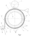
- eine stark schematisch vereinfacht und teils geschnitten gezeichnete Seitenansicht auf eine Vorrichtung zur Durchführung eines Verfahrens zwecks Erhalt des erfindungsgemäßen Verschlussteils;
- Fig. 2
- in stark vergrößerter Darstellung einen Längsschnitt durch einen Formhohlraum gemäß der Darstellung nach der
Fig. 1 ; - Fig. 3
- ein einzelnes Verschlusselement, wie es mit dem Formhohlraum nach der
Fig. 2 herstellbar ist; - Fig. 4
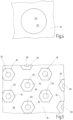
- eine Unteransicht auf das Verschlusselement nach
Fig. 3 ; - Fig. 5
- eine Draufsicht auf Verschlusselemente, von denen in der
Fig. 3 ein einzelnes dargestellt ist.
- Fig.1
- a highly schematically simplified and partly sectioned side view of a device for carrying out a method for obtaining the closure part according to the invention;
- Fig.2
- in a greatly enlarged view a longitudinal section through a mold cavity according to the illustration according to
Fig.1 ; - Fig.3
- a single closure element, as it is connected to the mold cavity after
Fig.2 can be produced; - Fig.4
- a bottom view of the closure element after
Fig.3 ; - Fig.5
- a plan view of closure elements, of which in the
Fig.3 a single one is shown.
Zu diesem Zweck weist die Formwalze 5 am Umfang ein Sieb 11 auf mit einzelnen Formhohlräumen 12. Ein dahingehender Formhohlraum 12 ist beispielhaft in der
Die
Wie die
Zum Erhalt der angesprochenen Formhohlräume 12 mit ihrem rotationssymmetrischen Aufbau, in Form eines Hyperboloids, haben sich galvanische Beschichtungsverfahren erwiesen, bei dem zunächst ein zylindrischer Formhohlraum (nicht dargestellt) derart mit einem Beschichtungswerkstoff beschichtet wird, bis sich der konvexe Bahnverlauf 14 einstellt. Ferner ließe sich gegebenenfalls auch über ein Laser- oder Ätzverfahren der konvexe Bahnverlauf 14 aus einem Sieb- oder Gitter-Vollmaterial erzeugen.To obtain the mentioned
Das in der
Ferner lässt sich gemäß der Darstellung nach der
Wie sich des Weiteren aus der
Die jeweilige weitere kraterartige Vertiefung 23 verläuft, ausgehend von der eben verlaufenden weiteren Seite 22 des Trägerteils 10 von dort überstandsfrei aus, stetig bis zum Kratergrund 24. Die jeweilige weitere Vertiefung 23 geht in einem Längsschnitt gemäß der Darstellung nach der
Des Weiteren ist in Blickrichtung auf die
Vorzugsweise ist jedem Verschlusselement zugeordnet eine solche weitere kraterartige Vertiefung 23 vorhanden, wobei alle Verschlusselemente bevorzugt gleich ausgebildet sind, ebenso wie alle weiteren kraterartigen Vertiefungen 23 zueinander. Dies gilt auch entsprechend für die kopfseitige konvexe Ausnehmung 20 auf der Oberseite des jeweiligen Kopfteiles 16 eines Verschlusselementes. Wie insbesondere die
Wie sich weiter aus der
Als Kunststoffe für das Verschlussteil werden solche Materialien bevorzugt eingesetzt mit einer Reißdehnung größer 30% und die vorstehend angegebenen Größen- und Dickenabmessungen sind bevorzugt mit einem DM2000-Dickenmessgerät der Firma Wolff-Messtechnik gemessen. Neben den üblichen Kunststoffmaterialien zum Herstellen solcher Verschlussteile können auch biologisch abbaubare Werkstoffe in Frage kommen, die vorzugsweise auf der Basis nachwachsender oder petrochemischer Rohstoffe oder aus Kombinationen beider hergestellt werden können.The plastics used for the closure part are preferably those with an elongation at break of more than 30% and the size and thickness dimensions given above are preferably measured with a DM2000 thickness gauge from Wolff-Messtechnik. In addition to the usual plastic materials for producing such closure parts, biodegradable materials can also be used, which can preferably be produced on the basis of renewable or petrochemical raw materials or from combinations of both.
An der Stelle der Entformung 27 (vgl.
Eine andere Möglichkeit die weiteren krater- oder dellenartigen Vertiefungen 23 einzubringen, besteht darin, dass man entweder die Druckwalze 3 und/oder eine Entformungswalze 28 (s.
Claims (9)
- A fastener part consisting of at least one planar substrate part (10), on one side of which a plurality of mushroom-head-like fastener elements are arranged, each of which, as an integral part of the substrate part (10), has a solid stem part (17) formed in the manner of a rotational hyperboloid and extending along a longitudinal axis, wherein to the free end of said stem part (17) a head part (16) adjoins, the edge regions of which form hooking possibilities and project at least partially beyond the stem part (17), and wherein said head part (16) has a crater-like depression (20) on its upper side, characterized in that a plurality of further crater-like depressions (23) is incorporated into the further side (22) of the substrate part (10), opposite to the fastener elements, in that both crater-like depressions (20, 23) of at least some of the fastener elements extend concentrically or mainly concentrically to the longitudinal axis of the respective assigned stem part (17), and in that the respective further crater-like depression (23) has a maximum crater depth ranging between 30 to 60%, preferably 50%, of the thickness of the substrate part (10).
- The fastener part according to claim 1, characterized in that the respective further crater-like depression (23), starting from the plane further side (22) of the substrate part (10), extends continuously from there without protrusion to the crater base (24).
- The fastener part according to claim 1 or 2, characterized in that the respective further crater-like depression (23), as viewed idealized in a longitudinal cross section, transitions starting from the further side (22) of the substrate part (10) from a convex into a concave course of curvature in the direction of the crater base (24).
- The fastener part according to any one of the preceding claims, characterized in that the concave course of curvature is less strongly bent than the convex course.
- The fastener part according to any one of the preceding claims, characterized in that the respective further crater-like depression (23), viewed in a longitudinal direction (25) of the substrate part (10) corresponding to the direction of manufacture, in turn, viewed in longitudinal cross section runs off more flatly on one side towards the further side (22) of the substrate part (10) than on the opposite cross-sectional side.
- The fastener part according to any one of the preceding claims, characterized in that a further crater-like depression (23) is provided assigned to every fastener element and that all fastener elements are of identical design, as are all further crater-like depressions (23) with respect to one another.
- The fastener part according to any one of the preceding claims, characterized in that the respective stem part (17) of a fastener element at least at its foot-sided transition point (18) towards the substrate part (10) forms the uniformly extending rotational body, wherein said transition point (18) has a smaller curvature than the transition of the stem part (17) to the head-sided widening (16) having the hooking points (21) of the fastener element, and in that the course of curvature at every location of the adjacent and opposite further crater-like depressions (23) has a smaller curvature than the curvature relating to the head-sided course of curvature of the stem part (17).
- The fastener part according to any one of the preceding claims, characterized in that the largest diameter of the further crater-like depression (23) at the point of expiring to the further side (22) of the substrate part (10) is larger than the diameter of the stem part (17) at any point between its foot end (18) and its head end (16), preferably larger than the extension of the head part (16) at its widest point.
- The fastener part according to any one of the preceding claims, characterized in that an adhesive agent is introduced into the further crater-like depression (23).
Applications Claiming Priority (2)
| Application Number | Priority Date | Filing Date | Title |
|---|---|---|---|
| DE102020007585.1A DE102020007585A1 (en) | 2020-12-11 | 2020-12-11 | locking part |
| PCT/EP2021/082285 WO2022122345A1 (en) | 2020-12-11 | 2021-11-19 | Fastener part |
Publications (2)
| Publication Number | Publication Date |
|---|---|
| EP4132315A1 EP4132315A1 (en) | 2023-02-15 |
| EP4132315B1 true EP4132315B1 (en) | 2024-05-15 |
Family
ID=78806525
Family Applications (1)
| Application Number | Title | Priority Date | Filing Date |
|---|---|---|---|
| EP21815492.0A Active EP4132315B1 (en) | 2020-12-11 | 2021-11-19 | Fastener part |
Country Status (7)
| Country | Link |
|---|---|
| US (1) | US20230320464A1 (en) |
| EP (1) | EP4132315B1 (en) |
| JP (1) | JP2023547013A (en) |
| CN (1) | CN116249609A (en) |
| DE (1) | DE102020007585A1 (en) |
| TW (1) | TW202228545A (en) |
| WO (1) | WO2022122345A1 (en) |
Family Cites Families (18)
| Publication number | Priority date | Publication date | Assignee | Title |
|---|---|---|---|---|
| ES453167A1 (en) * | 1976-11-10 | 1977-11-16 | Velero Espanola S A | Fastener device and method of manufacturing |
| US5845375A (en) * | 1990-09-21 | 1998-12-08 | Minnesota Mining And Manufacturing Company | Mushroom-type hook strip for a mechanical fastener |
| US5212853A (en) | 1992-03-10 | 1993-05-25 | Nifco Inc. | Separable plastic fastener and method and apparatus for manufacturing thereof |
| JPH09238714A (en) * | 1996-03-04 | 1997-09-16 | Ykk Corp | Integrally molded hook-and-loop fastener made of synthetic resin |
| DE19646318A1 (en) | 1996-11-09 | 1998-05-14 | Binder Gottlieb Gmbh & Co | Efficient process for the production of an adhesive closure part from thermoplastic plastic |
| DE19828856C1 (en) * | 1998-06-29 | 1999-10-07 | Binder Gottlieb Gmbh & Co | Process to mold a holding stud on a thermoplastic tab for baby nappies |
| DE10039937A1 (en) | 2000-08-16 | 2002-03-07 | Binder Gottlieb Gmbh & Co | Method of making an adhesive fastener part |
| US7246416B2 (en) | 2000-10-19 | 2007-07-24 | Leonard Arnold Duffy | Slidingly Engagable Fasteners and method |
| JP3818431B2 (en) * | 2001-03-08 | 2006-09-06 | Ykk株式会社 | Integrally molded surface fastener, its continuous manufacturing method and continuous manufacturing apparatus |
| DE10123205A1 (en) * | 2001-05-12 | 2002-11-28 | Binder Gottlieb Gmbh & Co | Production of section of touch-and-close fastener with support strip with integral hooks comprises adding mushroom-shaped layer of duroplast to top of hooks |
| DE102004058257B4 (en) | 2004-12-03 | 2007-05-16 | Binder Gottlieb Gmbh & Co Kg | Method for producing a carrier web and carrier web |
| US7516524B2 (en) * | 2005-03-11 | 2009-04-14 | Velcro Industries B.V. | Hook fastener components and methods of their manufacture |
| US20080134476A1 (en) * | 2006-12-11 | 2008-06-12 | Steindorf Eric C | Fastener having adjustable fastening strength |
| US8375529B1 (en) | 2008-07-29 | 2013-02-19 | Leonard Arnold Duffy | Touch engageable fastener |
| CN105189077B (en) * | 2013-02-22 | 2018-05-08 | 维尔克有限公司 | Contact securing member structure |
| US10016022B2 (en) * | 2015-10-07 | 2018-07-10 | Ykk Corporation | Hook fastener and methods for manufacturing same |
| US10292462B2 (en) | 2016-07-21 | 2019-05-21 | Florin Morar | Fastening device |
| CN113163907A (en) * | 2018-12-03 | 2021-07-23 | 维克罗知识产权控股有限责任公司 | Male touch fastener element |
-
2020
- 2020-12-11 DE DE102020007585.1A patent/DE102020007585A1/en active Pending
-
2021
- 2021-11-19 WO PCT/EP2021/082285 patent/WO2022122345A1/en active Application Filing
- 2021-11-19 CN CN202180060356.2A patent/CN116249609A/en active Pending
- 2021-11-19 US US18/013,606 patent/US20230320464A1/en not_active Abandoned
- 2021-11-19 JP JP2023512242A patent/JP2023547013A/en active Pending
- 2021-11-19 EP EP21815492.0A patent/EP4132315B1/en active Active
- 2021-12-09 TW TW110146045A patent/TW202228545A/en unknown
Also Published As
| Publication number | Publication date |
|---|---|
| EP4132315A1 (en) | 2023-02-15 |
| WO2022122345A1 (en) | 2022-06-16 |
| JP2023547013A (en) | 2023-11-09 |
| US20230320464A1 (en) | 2023-10-12 |
| DE102020007585A1 (en) | 2022-06-15 |
| CN116249609A (en) | 2023-06-09 |
| TW202228545A (en) | 2022-08-01 |
Similar Documents
| Publication | Publication Date | Title |
|---|---|---|
| EP1309257B1 (en) | Method for producing an adhesive closing element | |
| EP0932346B1 (en) | Method and device for producing a hook-and-pile type closure part from thermoplastic plastics | |
| EP1091664B1 (en) | Method for producing a fixing closure element | |
| DE69631646T2 (en) | Cast surface fastener and method and device for its production | |
| EP1827795B1 (en) | Method for producing a supporting web, and supporting web | |
| EP1358855B1 (en) | Process for manufacturing parts by freeform laser-sintering | |
| DE60118614T2 (en) | METHOD AND FORM FOR PRODUCING A LAYERED PART, ESPECIALLY REACTION INJECTION METHOD FOR PRODUCING A POLYURETHANE SKIN | |
| EP2129254A1 (en) | Method for the production of an adhesive closure device together with apparatus and adhesive closure device produced accordingly | |
| EP1063071A2 (en) | Polymer object with a structured surface, in particular tyre, mould and manufacturing of the mould | |
| EP2802233B1 (en) | Method for producing a plastics product and device for carrying out the method | |
| EP2836347B1 (en) | Injection moulded container made of plastic | |
| DE2166679C3 (en) | Embossing roller | |
| EP2593299B1 (en) | Steering wheel having a cover and method for the production thereof | |
| EP1882423B1 (en) | Process for manufacturing a touch fastener part | |
| EP4132315B1 (en) | Fastener part | |
| DE102008027860A1 (en) | Adhesive closure part and method for producing an adhesive closure part | |
| EP1626636B1 (en) | Method for producing a contact-fastener part | |
| EP0954435B1 (en) | Method for producing a composite bathtub | |
| WO2002091869A1 (en) | Method for producing a touch-and-close fastener element | |
| EP2771161B1 (en) | Nanoshaping-structure | |
| EP3655221B1 (en) | Method for producing a tool for a negative skin | |
| DE102006046130A1 (en) | Producing a coated large-area part comprises varying the amount and/or composition of polyurethane material deposited on the part in lines or sections | |
| EP1702743A1 (en) | Thermoforming process, in-mould film, forming sheet and plastic product | |
| DE102007049991B4 (en) | Trim part with a decorative skin and a foam layer and method for producing a trim part | |
| DE102016120410A1 (en) | Method for producing an adhesive closure part |
Legal Events
| Date | Code | Title | Description |
|---|---|---|---|
| STAA | Information on the status of an ep patent application or granted ep patent |
Free format text: STATUS: UNKNOWN |
|
| STAA | Information on the status of an ep patent application or granted ep patent |
Free format text: STATUS: THE INTERNATIONAL PUBLICATION HAS BEEN MADE |
|
| PUAI | Public reference made under article 153(3) epc to a published international application that has entered the european phase |
Free format text: ORIGINAL CODE: 0009012 |
|
| STAA | Information on the status of an ep patent application or granted ep patent |
Free format text: STATUS: REQUEST FOR EXAMINATION WAS MADE |
|
| 17P | Request for examination filed |
Effective date: 20221216 |
|
| AK | Designated contracting states |
Kind code of ref document: A1 Designated state(s): AL AT BE BG CH CY CZ DE DK EE ES FI FR GB GR HR HU IE IS IT LI LT LU LV MC MK MT NL NO PL PT RO RS SE SI SK SM TR |
|
| GRAP | Despatch of communication of intention to grant a patent |
Free format text: ORIGINAL CODE: EPIDOSNIGR1 |
|
| STAA | Information on the status of an ep patent application or granted ep patent |
Free format text: STATUS: GRANT OF PATENT IS INTENDED |
|
| INTG | Intention to grant announced |
Effective date: 20231220 |
|
| DAV | Request for validation of the european patent (deleted) | ||
| DAX | Request for extension of the european patent (deleted) | ||
| GRAS | Grant fee paid |
Free format text: ORIGINAL CODE: EPIDOSNIGR3 |
|
| GRAA | (expected) grant |
Free format text: ORIGINAL CODE: 0009210 |
|
| STAA | Information on the status of an ep patent application or granted ep patent |
Free format text: STATUS: THE PATENT HAS BEEN GRANTED |